

Honeywell VISTA-20P, VISTA-20PSIA, VISTA-15P, VISTA-15PSIA Owner's Manual

ADEMCO VISTA SERIES
VISTA-20P / VISTA-20PSIA
VISTA-15P / VISTA-15PSIA
Security Systems
Programming Guide
K5305-1PRV5 10/04 Rev. A TO ENTER PROGRAMMING MODE (using an alpha keypad connected to
the control):
A. POWER UP, then press [✱] and [#] at the same time, within 50 seconds of powering up (this method must be used if ✱98
was used to exit program mode). OR
B. Initially, key: Installer Code (4 + 1 + 1 + 2) plus 8 + 0 + 0.
– 2 – Downloaded
PROGRAMMING MODE COMMANDS
Task
Command/Explanation
Go to a Data Field
Press [∗] + [Field Number], followed by the required entry.
Entering Data
When the desired field number appears, simply make the required entry. When the last entry
for a field is entered, the keypad beeps three times and automatically displays the next data
field in sequence. If the number of digits that you need to enter in a data field is less than the
maximum digits available (for example, the phone number fields *41, *42), enter the desired
data, then press [∗ ] to end the entry. The next data field number is displayed.
Review a Data Field
Press [#] + [Field Number].
Data will be displayed for that field number. No changes will be accepted in this mode.
Deleting an Entry
Press [∗] + [Field Number] + [∗]. (Applies only to fields ∗40 thru *46, *94, and pager fields)
Initialize Download ID
Press ∗96. Initializes download ID and subscriber account number.
Reset Factory Defaults
Press ∗97. Sets all data fields to original factory default values.
Zone Programming
Press ∗56. Zone characteristics, report codes, alpha descriptors, and serial numbers for 5800
RF transmitters.
Function Key Programming
Press ∗57. Unlabeled keypad keys (known as ABCD keys) for special functions
Zone Programming (Expert
Mode)
Press ∗58. Same options as *56 mode, but with fewer prompts. Intended for those familiar with
this type of programming, otherwise *56 mode is recommended.
Output Device Mapping
Press ∗79. Assign module addresses and map individual relays/powerline carrier devices
Output Programming
Press ∗80. 4229 or 4204 Relay modules, Powerline Carrier devices, or on-board triggers
Zone List Programming
Press ∗81. Zone Lists for relay/powerline carrier activation, chime zones, pager zones, etc.
Alpha Programming
Press ∗82. Zone alpha descriptors
Exit Program Mode with
installer code lockout
Press ∗98. Exits programming mode and prevents re-entry by: Installer Code + 8 + 0 + 0. To
reenter programming mode, the system must be powered down, then powered up. Then use
method A above. See field *88 for other *98 Program mode lockout options.
Exit Program Mode
Press ∗99. Exits programming mode and allows re-entry by: Installer Code + 8 + 0 + 0 or
method A above.
SPECIAL MESSAGES
OC = OPEN CIRCUIT (no communication between Keypad and Control).
EE or ENTRY ERROR = ERROR (invalid field number entered; re-enter valid field number).
After powering up, AC, dI (disabled) or Busy Standby and NOT READY will be displayed after approximately 4 seconds.
This will revert to a “Ready” message in approximately 1 minute, which allows PIRS, etc. to stabilize. You can bypass this
delay by pressing [#] + [0].
If E4 or E8 appears, more zones than the expansion units can handle have been programmed. The display will clear after you
correct the programming.
TABLE OF DEVICE ADDRESSES
This Device
Uses Address
Reports as ††
Enabled By…
RF Receiver
00
100
*56 zone programming: input device type entry
AUI 1
01
101
Automatic if AUI enable field *189 enabled for AUI 1
AUI 2
02
102
Automatic if AUI enable field *189 enabled for AUI 2
Long Range Radio
03
103
automatic if output to long range radio field *29 enabled
4286 Voice Module
04
104
automatic if phone module access code field *28 enabled
Zone Expanders (4219/4229):
module 1 (for zones 09 - 16)
module 2 (for zones 17 - 24)
module 3 (for zones 25 - 32)
module 4 zones 33 - 40
module 5 zones 41 - 48
07
08
09**
10**
11**
107
108
109
110
111
*56 zone programming: input device type entry, then: automatic if
zone no. 9-16 entered as AW type or relay assigned automatic if
zone no. 17-24 entered as AW type or relay assigned automatic if
zone no. 25-32 entered as AW type or relay assigned automatic if
zone no. 33-40 entered as AW type or relay assigned automatic if
zone no. 41-48 entered as AW type or relay assigned
Relay Modules (4204):
module 1 module
2 module 3
module 4
12
13
14**
15**
112
113
114
115
*79 output device programming: device address prompt:
entered at device address prompt entered at device
address prompt entered at device address prompt
entered at device address prompt
– 3 – Downloaded
Keypads: keypad
1 keypad 2
keypad 3
keypad 4
keypad 5
keypad 6
keypad 7
keypad 8
16
17
18
19
20
21
22
23
n/a n/a
n/a n/a
n/a n/a
n/a
n/a
data field programming as listed below: always
enabled, all sounds enabled.
data field *190 data
field *191 data field
*192 data field
*193 data field
*194 data field
*195 data field
*196
5800TM Module
28
n/a
automatic
** These module addresses apply to VISTA-20P only.
†† Addressable devices are identified by “1” plus the device address when reporting. Enter report code for zone 91 to enable addressable device
reporting (default = reports enabled). See field *199 for addressable device (ECP) 3-digit/2-digit identification keypad display options.
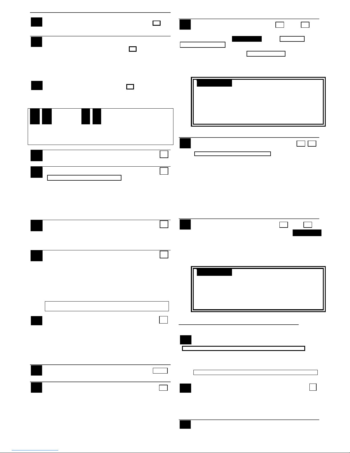
PROGRAMMING FORM
Entries apply to the ADEMCO VISTA-15P/VISTA-15PSIA and ADEMCO VISTA-20P/VISTA-20PSIA controls, except entries shown in dashed
boxes, which apply only to the VISTA-20P/VISTA-20PSIA (partition entries) and are not applicable to the VISTA-15P/VISTA-15PSIA. In addition,
where noted, certain fields have special settings when used with the VISTA-20PSIA/VISTA-15PSIA (indicated by V20PSIA/V15PSIA with heavy
borders and reverse type throughout for easy identification).
Entry of a number other than one specified will give unpredictable results. Values shown in brackets are factory defaults.
SIA Guidelines: Notes in certain fields give instructions for programming the VISTA-20P/VISTA-15P for False Alarm Reduction.
∗20 Installer Code [4112] | | |
4 digits, 0–9
∗21 Quick Arm Enable [0,0]
0 = no; 1 = yes Part. 1 Part.2
∗22 RF Jam Option [0]
0 = no RF Jam detection; 1 = send RF Jam
report UL: must be 1 if wireless devices are used
∗23 Quick (Forced) Bypass [0,0]
0 = no quick bypass UL: must be “0” Part. 1 Part. 2
1 = allow quick bypass (code + [6] + [#] )
∗24
RF House ID Code
[00,00,00]
| |
00 = disable all wireless keypad usage Part. 1 Part. 2
01–31 = using 5827, 5827BD or 5804BD keypad
|
Common
∗26
Chime By Zone
[0]
0 = no; 1 = yes (list chime zones on zone list 3 using *81 Menu mode)
∗27 Powerline Carrier Device (X–10)
[0]
House Code
0 = A; 1 = B; 2 = C; 3 = D; 4 = E; 5 = F; 6 = G; 7 = H; 8 = I; 9 = J;
#10 = K; #11 = L; #12 = M; #13 = N; #14 = O; #15 = P
UL: not for fire or UL installations
∗28
Access Code For Phone Module [00] |
00 = disable; (Partition 1 only)
1st digit: enter 1–9; 2nd digit: enter # + 11 for "✱", or # + 12 for "#".
UL: must be “00” for UL Commercial Burg. installations
∗29
Long Range Radio Output [0]
0 = disable; 1 = enable
∗31
Single Alarm Sounding Per Zone [0]
0 = unlimited sounding; 1 = one alarm sounding per zone
V20PSIA/V15PSIA: If “0” selected, “alarm sounding per zone” will be the
same as the “number of reports in armed period” set in field *93 (1 if one
report, 2 if 2 reports, unlimited for zones in zone list 7).
∗32 Fire Alarm Sounder Timeout
[0]
0 = sound stops at timeout; 1 = no timeout UL: must be “1” for fire install.
∗33 Alarm Sounder (Bell) Timeout
[1]
0 = none; 1 = 4 min; 2 = 8 min; 3 =12 min; 4 = 16 min;
UL: For residential fire alarm installation, must be set for a minimum of
4 min (option 1); for UL Commercial Burglary installations, must be
minimum 16 min (option 4)
00 - 96 = 0 - 96 secs; 97 = 120 secs Part. 1
SIA Guidelines: minimum exit delay is 45 seconds
V20PSIA/V15PSIA:
45 - 96 = 45 - 96 secs; 97 = 120 secs
delay.
UL: see inst. instr. for requirements. Common zones use part. 1 delay.
∗35 Entry Delay #1 [30,30] | |
Common zones use same delay as partition 1. Part. 1 Part. 2
00 - 96 = 0 - 96 seconds; 97 = 120 secs; 98 = 180 secs; 99 = 240 secs
SIA Guidelines: minimum entry delay is 30 seconds
V20PSIA/V15PSIA:
30-96 = 30 - 96 secs; 97 = 120 secs; 98 = 180 secs; 99 = 240 secs NOTE:
Entries less than 30 will result in a 30-second delay.
For UL Residential Burglary Alarm installations, must be set for a
maximum of 30 seconds; entry delay plus dial delay should not exceed 1
min. For UL Commercial Burglar Alarm, total entry delay may not
exceed 45 seconds.
∗36 Entry Delay #2 [30,30] | |
See *35 Entry Delay 1 for entries. Part. 1 Part. 2
∗37 Audible Exit Warning [1,1]
0 = no; 1 = yes (SIA Guidelines: must be enabled) Part. 1 Part. 2
∗
34
Exit Delay
[60,60]
|
|
Part. 2
– 4 – Downloaded
V20PSIA/V15PSIA: feature always enabled; field does not exist
∗38 Confirmation Of Arming Ding [0,0]
0 = no; 1 = yes (wired keypads and RF) Part. 1 Part. 2
2 = yes, RF only
UL: must be “1” for UL Commercial Burglar Alarm inst.
∗39 Power Up In Previous State [1]
0 = no, always power up disarmed; 1 = yes, power up in previous
state UL: must be “1” SIA Guidelines: must be “1”
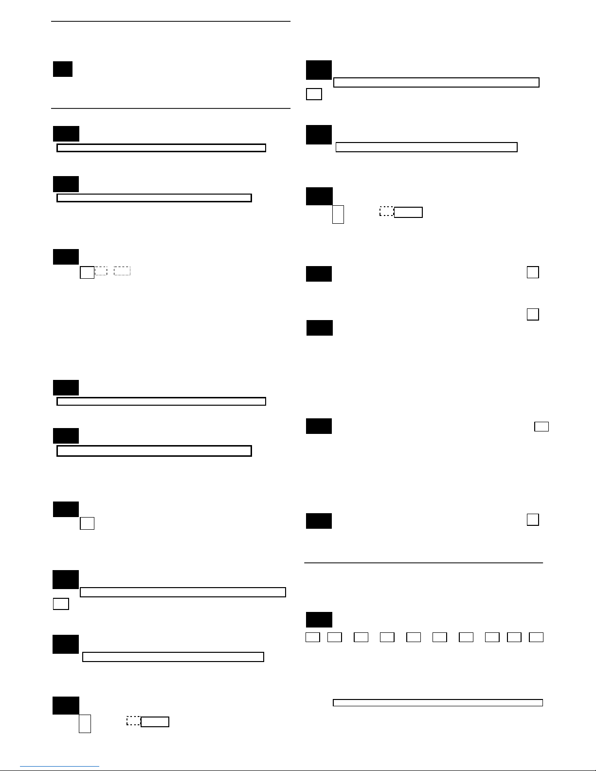
DIALER PROGRAMMING (✱40 – ✱42)
Do not fill unused spaces. Enter 0–9; #+11 for '✱'; #+12 for '#'; #+13 for a
2second pause. If fewer than the maximum digits entered, exit the field by
pressing [✶]. The next data field number is displayed.
∗40 PABX Access Code or | | | | |
Call Waiting Disable Enter up to 6 digits. To clear entries,
press ✱40✱. If call waiting is used, enter call waiting disable digits “∗
(#+11) 70” plus “# + 13” (pause).
NOTES: 1. The call waiting disable feature cannot be used on a
PABX line.
2. Using Call Waiting Disable on a non-call waiting line will
prevent successful communication to the central station.
V20PSIA/V15PSIA:
If call waiting is used, enter call waiting disable digits
∗41 Primary Phone No.
| | | | | | | | | | | | | | | | | | |
∗42 Second Phone No.
| | | | | | | | | | | | | | | | | | |
Enter up to 20 digits. To clear entries, press ✱41✱ or ✱42✱ respectively.
NOTE: For fields *43 thru *46: Enter 0–9; #+11 for B; #+12 for C; #+13 for
D; #+14 for E; #+15 for F. Enter [✱] as the fourth digit if a 3-digit account
number (for 3+1 dialer reporting format) is used. Enter 0 as the first digit of
a 4-digit account number for Nos. 0000-0999. Exit field by pressing ✱ if only
3 digits are used. E.g., For Acct. B234, enter: #+11 + 2 + 3 + 4
∗43 Partition 1 Primary Acct. No.
| | | / | | | | | [FFFFFFFFFF] Enter 4 or 10 digits, as chosen
in *48 Report Format. See box above. To clear entries, press *43*.
∗44 Part. 1 Secondary Acct. No. (see field *43 for
entries)
| | | / | | | | | [FFFFFFFFFF] To clear, press *44*.
∗45 Partition 2 Primary Acct. No. (see field *43 for
entries)
| | | / | | | | | [FFFFFFFFFF] To clear, press *45*.
∗46 Partition 2 Secondary Acct. No. (see field *43 for entries)
| | | / | | | | |
[FFFFFFFFFF] To clear, press *46*.
∗47
Phone System Select [1]
If Cent. Sta. is not on a WATS line: 0=Pulse Dial; 1=Tone Dial;
if Cent. Sta. is on a WATS line: 2 = Pulse Dial ; 3 = Tone Dial
∗48
Report Format [77]
0 = 3+1, 4+1 ADEMCO L/S STANDARD primary secondary
1 = 3+1, 4+1 RADIONICS STANDARD
2 = 4+2 ADEMCO L/S STANDARD
3 = 4+2 RADIONICS STANDARD
5 = 10-digit ADEMCO CONTACT ID® REPORTING
6 = 4+2 ADEMCO EXPRESS
7 = 4-digit ADEMCO CONTACT ID® REPORTING
8 = 3+1, 4+1 ADEMCO L/S EXPANDED
9 = 3+1, 4+1 RADIONICS EXPANDED
– 5 – Downloaded
∗49 Split/Dual Reporting [0]
0 = Standard/backup reporting only (all to primary)
Primary Phone No. 2nd Phone No.
1 = Alarms, Restore, Cancel Others
2 = All except Open/Close, Test Open/Close, Test
3 = Alarms, Restore, Cancel All 4 = All except Open/Close, Test
All
5 = All All
∗50 Burglary Dialer Delay [2,0]
Delay Time: Delay Time V20PSIA/V15PSIA
0 = no delay UL: must be “0” Delay Disable
1 = 15 seconds; 2 = 30 seconds; 3 = 45 seconds
SIA Guidelines: delay must be minimum of 30 seconds
V20PSIA/V15PSIA:
1
Delay Time: 1
Delay Disable:
0 = use delay set in entry
1
∗54 Dynamic Signaling Delay [0]
Select delay from 0 to 225 secs, in 15-sec increments.
0 = no delay (both signals sent); 1 = 15 secs; 2 = 30 secs, etc.
UL: Grade AA must be “0;” Grade A must be “15” max
∗55 Dynamic Signaling Priority [0]
0 = Primary Dialer first; 1 = Long Range Radio first.
For UL Commercial Burglary installations that use a DACT and
LRR, this field must be “0”.
∗56
,
∗57
,
∗58
Menu Modes
document.
TO PROGRAM SYSTEM STATUS, & RESTORE REPORT CODES (∗59 thru
∗68, *70 thru ∗76, and ∗89):
For 3+1 or 4+1 Standard Format: Enter a code in the first box: 1–9, #+10 for
0, #+11 for B, #+12 for C, #+13 for D, #+14 for E, #+15 for F.
A 0 (not #+10) in the first box will disable a report. A 0 (not #+10)
in the second box will result in automatic advance to the next field.
For Expanded or 4+2 Format: Enter codes in both boxes (1st and 2nd digits)
for 1–9, 0, or B–F, as described above.
A 0 (not #+10) in the second box will eliminate the expanded
message for that report. A 0 (not #+10) in both boxes will disable the report.
For Ademco Contact ID® Reporting: Enter any digit (other than 0) in the
first box, to enable zone to report (entries in the second boxes are ignored).
A 0 (not #+10) in the first box disables the
report. UL: see installation instructions for
requirements
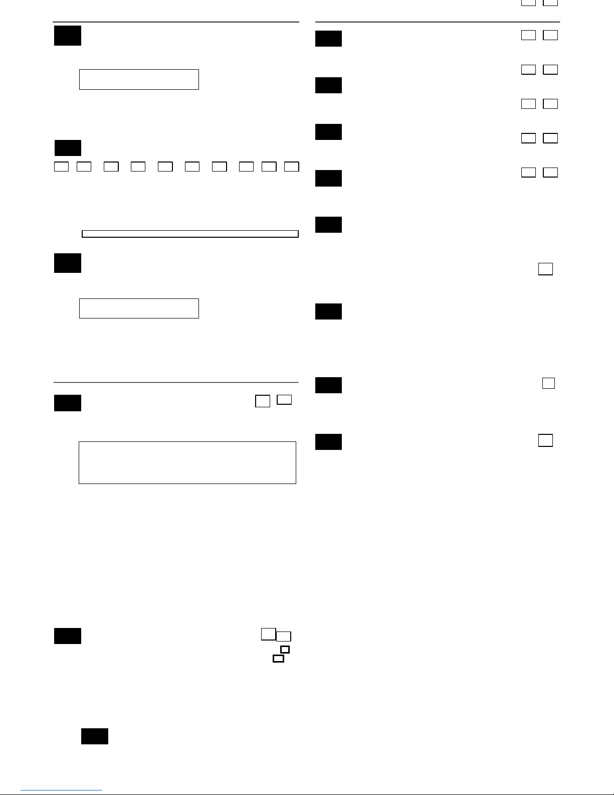
SYSTEM STATUS REPORT CODES (✱59–✱ 68)
∗59 Exit Error Alarm Report Code [0]
See above for entries. V20PSIA/V15PSIA: [1] Always enabled.
∗60 Trouble Report Code [00] |
∗61 Bypass Report Code [00] |
∗62 AC Loss Report Code [00] |
∗63 Low Bat Report Code [00] |
∗64 Test Report Code [00] |
Use Scheduling mode to set periodic test reports, or use the following key
commands:
installer code +[#] + [0] + 0 = test report sent every 24
hours installer code +[#] + [0] + 1 = test report sent once per
week installer code +[#] + [0] + 2 = test report sent every 28
day
Each mode sets schedule 32 (VISTA-20P) or schedule 08 (VISTA-15P)
to the stated repeat option; first test report sent 12 hours after
command.
∗65 Open Report Code [0,0,0]
Part. 1 Part. 2 Common
∗66 Arm Away/Stay Rpt Code
[0,0,0,0,0,0]
Away Stay Away Stay Away Stay
Part. 1 Part. 2 Common
∗67 RF Trans. Low Bat Report Code [00] |
UL: must be enabled if wireless devices are used
RESTORE REPORT CODES (✱70 – ✱76) ∗70
Alarm Restore Rpt Code [0]
∗71 Trouble Restore Rpt Code [00] |
∗72 Bypass Restore Rpt Code [00] |
∗73 AC Restore Rpt Code [00] |
∗74 Low Bat Restore Rpt Code [00] |
∗75 RF Trans. Lo Bat Rst Rpt Code [00] |
UL: must be enabled if wireless devices are used
∗
53
SESCOA/Radionics Select
[0]
0 = Radionics (0-9, B-F); enter “0” for all non-SESCOA formats
1 = SESCOA (0-9 only reporting)
∗
68
Cancel Report Code
|
[00]
V20PSIA/V15PSIA:
[10] Report enabled.
∗
69
Recent Closing Report Code
|
[11]
V20PSIA/V15PSIA:
Always enabled.
Field does not apply to other controls.
– 6 – Downloaded
∗76 Test Restore Rpt Code [00] |
OUTPUT AND SYSTEM SETUP (✱77 – ✱93) ∗77
Daylight Savings Time [4][10] |
Start/End Month
0 = Disabled
1-12 = January-September (1 = Jan, 2 = Feb, etc)
#+10 = October; #+11 = November; #+12 = December
∗78 Daylight Savings Time [1][5] |
Start/End Weekend
0 = disabled; 1 = first; 2 = second; 3 = third; 4 = fourth;
5 = last; 6 = next to last; 7 = third to last
∗79
,
*80
,
*81
,
*82
Menu Modes
∗84
Auto Stay Arm [3]
0 = no; 1 = partition 1 only; 2 = partition 2 only; 3 = both partitions
∗85
Cross Zone Timer [0]
This option not for use in UL installations.
(assign cross zones on zone list 4, using *81 Menu mode)
0 = 15 seconds 6 = 2-1/2 min #+12 = 8 min
1 = 30 seconds
7 = 3 min
#+13 = 10 min
2 = 45 seconds
8 = 4 min
#+14 = 12 min
3 = 60 seconds
9 = 5 min
#+15 = 15 min
4 = 90 seconds
5 = 2 minutes #+11 = 7
#+10 = 6 min
min
∗86
Cancel Verify Keypad Display [1]
0 = no “alarm canceled” display
1 = display “Alarm Canceled” when system is disarmed after an alarm
has occurred. (To clear the “ALARM CANCELED” display, the
user must enter the security code + OFF again.)
∗87
Misc. Fault Delay Time [0]
(used with Configurable Zone Types “digit 6”)
0 = 15 seconds 6 = 2-1/2 min #+12 = 8 min
1 = 30 seconds 7 = 3 min #+13 = 10 min
2 = 45 seconds 8 = 4 min #+14 = 12 min
3 = 60 seconds 9 = 5 min #+15 = 15 min
4 = 90 seconds #+10 = 6 min
5 = 2 minutes #+11 = 7 min
UL: may only be used on non-burglar alarm/ non-fire alarm zones
when used in fire and/or UL burglar alarm installation
∗88 Program Mode Lockout Options [0]
0 = standard *98 installer code lockout (reentry only by [∗] + [#] within
50 seconds after power up)
1 = lockout [∗] + [#] reentry after *98 exit (reenter via installer code or
downloader only)
2 = not used
3 = lockout local programming after *98 exit (reenter by downloader
only)
NOTE: System messages are logged when any non-zero entry is made.
0 = None; 1 = Alarm/Alarm Restore
2 = Trouble/Trouble Restore;
4 = Bypass/Bypass Restore;
8 = Open/Close. Example: To select “Alarm/Alarm Restore”, and
“Open/Close”, enter 9 (1 + 8); To select all, enter #15.
[8, 0]
Options: 0 = None Options V20PSIA/V15PSIA 4 = AAV UL: must use
ADEMCO UVCM module Call Wait Disable
8 = Exit Delay Restart/Reset UL: must be disabled
#+12 = AAV and Exit Delay
Restart/Reset SIA Guidelines: Exit Delay
should be enabled.
V20PSIA/V15PSIA:
Options: Same as listed
above.
Call Waiting
Disable:
0 = call waiting not used
1
∗92 Phone Line Monitor Enable [0,0]
UL: see Inst. Instructions for requirements 1 2
NOTE: Output Device must either be programmed to be STOPPED in
field ✱80 or STOPPED by Code + # + 8 + output number.
Entry 1:: 0 = disabled, 1-15 = 1 min - 15 min
(#+10 = 10 min; #+11 = 11 min; #+12 = 12 min; #+13 = 13 min; #+14
= 14 min; #+15 = 15 min)
Entry 2:
0 = Keypad display when line is faulted
1 = Keypad display plus keypad trouble sound
2 = Same as “1”, plus programmed output device STARTS. If either partition is
armed, external sounder activates also.
∗93 Reports In Armed Period [1,0]
Per Zone (Swinger Suppression) Restrict V20PSIA/V15PSIA
Restrict Report Pairs: Report Pairs Unlimited
0 = Unlimited Reports Reports Enable
1 = 1 report pair
2 = 2 report pairs SIA Guidelines: Must be set for option 1 or 2.
V20PSIA/V15PSIA:
1 = 1 report pair; 2 = 2 report pairs
Restrict Report
Pairs:
Unlimited Reports
Enable:
0
1
DOWNLOAD INFORMATION (✱94, ✱95)
∗94 Download Phone No.
| | | | | | | | | | | | | | | | | | |
Enter up to 20 digits, 0–9; #+11 for '✱'; #+12 for '#'; #+13 for a
2second pause. Do not fill unused spaces. If fewer than 20 digits, exit
field by pressing ✱. To clear entries from field, press ✱94✱.
UL: downloading may be performed only if a technician is at the site.
∗95 Ring Count For Downloading [15]
NOTE: Do not enter “0” if using 4285/4286 Phone Module.
0 = Disable Station Initiated Download;
1–14 = number of rings (1–9, # +10 =10, # +11
=11, # +12 =12, # +13 =13, # +14 =14); 15 =
answering machine defeat (# +15 =15).
∗96, ∗97 Initialize/Reset Defaults
∗
89
Event Log Full Report Code
[00]
|
See box above field *59 for report code entries.
∗
90
Event Log Enables
[3]
∗
91
Option Selection
– 7 – Downloaded
This is a command, not a data field. See page 2.
∗98, *99 Exit Commands
This is a command, not a data field. See page 2.
PAGER OPTIONS (✱160- ✱172)
∗160 Pager 1 Phone No.
| | | | | | | | | | | | | | | | | | |
Enter up to 20 digits. 0–9; #+11 = '✱'; #+12 = '#'; #+13 = 2-sec pause
∗161 Pager 1 Characters
| | | | | | | | | | | | | | |
Enter the optional prefix characters, up to 16 digits.
0–9; #+11 = '✱'; #+12 = '#'; #+13 = 2-second pause.
∗162 Pager 1 Report Options
[0,0,0]
Part. 1 Part. 2 common
For each partition, select from the following options:
0 = no reports sent
1 = Opens/closes all users
4 = All alarms and troubles
5 = All alarms / troubles, and opens/closes for all users
12 = Alarms / troubles for zones entered in zone list 9
13 = Alarms / troubles for zones entered in zone list 9, and opens/closes for all
users
∗163 Pager 2 Phone No.
| | | | | | | | | | | | | | | | | | |
Enter up to 20 digits. 0–9; #+11 = 'Q'; #+12 = '#'; #+13 = 2-sec pause
∗164 Pager 2 Characters
| | | | | | | | | | | | | | |
Enter the optional prefix characters, up to 16 digits.
0–9; #+11 = '✱'; #+12 = '#'; #+13 = 2-second pause.
∗165
Pager 2 Report Options
[0,0,0]
Part. 1 Part. 2 common
See field *162 for reporting options. Select for each partition (use zone
list 10 if using options 12 or 13).
Pager 3 Phone No.
| | | | | | | | | | | | | | | | |
| |
Enter up to 20 digits. 0–9; #+11 = '✱'; #+12 = '#'; #+13 = 2-sec pause
Pager 3 Characters
| | | | | | | | | | | | | | |
Enter the optional prefix characters, up to 16 digits.
0–9; #+11 = '✱'; #+12 = '#'; #+13 = 2-second pause.
Pager 3 Report Options
0,0,0]
Part. 1 Part. 2 common
See field *162 for reporting options. Select for each partition (use zone
list 11 if using options 12 or 13).
Pager 4 Phone No.
| | | | | | | | | | | | | | | | |
| |
Enter up to 20 digits. 0–9; #+11 = '✱'; #+12 = '#'; #+13 = 2-sec pause
Pager 4 Characters
| | | | | | | | | | | | | | |
Enter the optional prefix characters, up to 16 digits.
0–9; #+11 = '✱'; #+12 = '#'; #+13 = 2-second pause.
Pager 4 Report Options
[0,0,0]
Part. 1 Part. 2 common
See field *162 for reporting options. Select for each partition (use zone
list 12 if using options 12 or 13).
∗172 Pager Delay Option For Alarms [3]
0 = none; 1 = 1 minute; 2 = 2 minutes; 3 = 3 minutes
This delay is for ALL pagers in the system.
MISCELLANEOUS SYSTEM FIELDS (*174-*181)
∗174 Clean Me Reporting Options [0]
(for ESL smoke detectors)
0 = disable; 1 = Clean Me signal reports;
NOTE: If Clean Me is enabled, you must enter “3” in field ✱56
programming for zone 1 response time.
∗177 Device Duration 1, 2 [0] [0]
(used in *80 Menu mode-Device Actions 5/6)
0 = 15 seconds 6 = 2-1/2 min
#+11 = 7 min 1 = 30 seconds 7
= 3 min #+12 = 8 min
2 = 45 seconds 8 = 4 min #+13 = 10 min
3 = 60 seconds 9 = 5 min #+14 = 12 min
4 = 90 seconds #+10 = 6 min
#+15 = 15 min 5 = 2 minutes
1 2
∗181 50/60 Hertz AC Operation [0]
0 = 60 Hz; 1 = 50 Hz
CONFIGURABLE ZONE TYPE OPTIONS (*182-*185)
(see Configurable Zone Type Worksheet on page 7)
∗182 Configurable Zone Type 90
1 2 3 4 5 6 7 8 9 10
Enter the appropriate value for each entry, 1-10, based on the charts
provided on the next page. Each entry is the sum of the values of its
selected options
(0-9, #+10=10, #+11=11, #+12=12, #+13=13, #+14=14, #+15=15).
UL: Do not configure zones as a fire alarm or UL burglar alarm zone.
∗166
∗167
∗168
∗169
∗170
∗171
– 8 – Downloaded
Zone Type 90 Report Codes
IMPORTANT: Use existing Contact ID® codes, if appropriate, or
define unique codes in CID code range 750-789. See important note
in installation instructions.
90 ALARM ID: XXX
TROUBLE ID: XXX
Enter the desired 3-digit Contact ID® report codes for alarms and
troubles occurring on zones assigned to this zone type. Enter the
codes sequentially (all 6 digits). When entering digits, [#] moves
cursor back, [∗] moves forward. Press [∗] when done to continue.
∗184 Configurable Zone Type 91
1 2 3 4 5 6 7 8 9 10
Enter the appropriate value for each entry, 1-10, based on the charts
provided on the next page. Each entry is the sum of the values of its
selected options
(0-9, #+10=10, #+11=11, #+12=12, #+13=13, #+14=14, #+15=15).
UL: Do not configure zones as a fire alarm or UL burglar alarm zone.
Zone Type 91 Report Codes
IMPORTANT: Use existing Contact ID® codes, if appropriate, or
define unique codes in CID code range 750-789. See important note
in installation instructions.
91 ALARM ID: XXX TROUBLE
ID: XXX
Enter the desired 3-digit Contact ID® report codes for alarms and
troubles occurring on zones assigned to this zone type. Enter the
codes sequentially (all 6 digits). When entering digits, [#] moves
cursor back, [∗] moves forward. Press [∗] when done to continue.
∗189 AUI Device 1 and 2 Enable [1] [1]
(for Touch Screen Style Keypads) AUI 1
AUI 2
System supports up to two touch screen style keypads (e.g.,
Symphony Advanced User Interface, and 6270 Touch Screen Keypad).
AUI Compatibility Note: To ensure proper AUI device operation,
connect only to controls having microprocessor version 3.0 or
higher, and use AUI devices with the following rev levels: 6270
series use version 1.0.9 or higher; 8132/8142 (Symphony) series
use version 1.1.175 or higher.
Touch Screen (AUI) device 1: Must set AUI device address to 1
Touch Screen (AUI) device 2: Must set AUI device address to 2
VISTA-20P: Enter each touch screen keypad’s home partition
0 = disable; 1 = partition 1; 2 = partition 2; 3 = partition 3
(common) VISTA-15P: 0 = disable; 1 = enable
NOTE: Use of touch screen style keypads does not affect the number
of standard keypads supported.
KEYPAD OPTIONS *190-*196
NOTES: 1. Options for keypad address 16 are set by the factory and cannot be
changed.)
2. Each keypad must be assigned a unique address. Keypads
programmed with the same address will give unpredictable results.
∗190 Keypad 2 Device Address 17 [0] [0]
†Partition/Enable: Part./ Sound
†
VISTA-20P: Enter partition where: Enable
0 = keypad disabled; 1-3 = part. no. (3 = com) VISTA-15P: 1 =
enable; 0 = disable
Sound: 0 = no suppression
1 = suppress arm/disarm and E/E beeps
2 = Suppress chime beeps only 3 = suppress arm/disarm, E/E, and chime
beeps ∗191 Keypad 3 Device Address 18 [0] [0]
See field ∗190 for entries. Partition/ Sound
Enable
∗192 Keypad 4 Device Address 19 [0] [0]
See field ∗190 for entries. Partition/ Sound
Enable
∗193 Keypad 5 Device Address 20 [0] [0]
See field ∗190 for entries. Partition/ Sound
Enable
∗194 Keypad 6 Device Address 21 [0] [0]
See field ∗190 for entries. Partition/ Sound
Enable
∗195 Keypad 7 Device Address 22 [0] [0]
See field ∗190 for entries. Partition/ Sound
Enable
∗196 Keypad 8 Device Address 23 [0] [0]
See field ∗190 for entries.
Partition/
Sound
Enable
∗197 Exit Time Display Interval [0]
0 = no display; 1-5 = seconds between display refresh
NOTE: If enabled and using only 2-digit fixed-word keypads (e.g.,
6150RF), do not set exit delay time greater than 96 seconds. See Inst.
Instr. for explanation.
∗198 Display Partition Number [0]
(VISTA-20P; for Alpha Display Keypads)
0 = no; 1 = yes (partition no. appears on Alpha Display)
∗199 ECP Fail Display [0]
0 = 3-digit display (“1” + device address)
1 = 2-digit fixed-display as “91”
∗183
∗185
 Loading...