

Honeywell Vista-12D Installation And Setup Manual

DEE
AAD
MCC
M
O VViissttaa--1122
O
D
D
Installation and Set-Up Guide
This control complies with EN50131-1
K10022V1 4/05 Rev. A

Installation and Setup Guide
ii

Table Of Contents
•••••••••••••••••••••••••••••••••
Features and Installation Highlights .................................................................................................1-1
Capabilities ........................................................................................................................................... 1-1
Functions............................................................................................................................................... 1-1
Compatible Devices............................................................................................................................... 1-2
Important Installation Highlights (Installer Please Read) ................................................................1-3
Mounting and Wiring the Control....................................................................................................... 2-1
Cabinet and Lock .................................................................................................................................. 2-1
Mounting the PC Board........................................................................................................................ 2-1
Wiring to Keypads ................................................................................................................................2-3
Sounder (Siren) Connections................................................................................................................ 2-4
Wiring the AC Transformer ................................................................................................................. 2-5
Backup Battery ..................................................................................................................................... 2-6
Earth Ground........................................................................................................................................ 2-6
Basic Wired Zones................................................................................................................................. 2-7
Smoke Detectors ................................................................................................................................... 2-8
4219/4229 Expansion Zones ................................................................................................................. 2-9
6164 Keypad Expansion Zones........................................................................................................... 2-10
Installing the RF Receiver.................................................................................................................. 2-11
Installing a 5800TM Module.............................................................................................................. 2-11
Installing the Transmitters................................................................................................................ 2-12
Installing a Keyswitch........................................................................................................................ 2-12
Connecting Relay Modules ................................................................................................................. 2-14
Powerline Carrier Devices.................................................................................................................. 2-16
On-Board Triggers .............................................................................................................................. 2-17
Phone Line Connections ..................................................................................................................... 2-18
Alternative Communications Media (ACM) Connections ................................................................. 2-18
Audio Alarm Verification Connections (AAV, “Listen-In”) ............................................................... 2-18
Programming Overview ........................................................................................................................ 3-1
About Programming.............................................................................................................................. 3-1
Zones and Partitions............................................................................................................................. 3-2
Keypads ................................................................................................................................................. 3-2
Wireless Receiver Transmitters, and Wireless Keys (keyfobs)...........................................................3-3
Pager Programming.............................................................................................................................. 3-3
Function Keys ....................................................................................................................................... 3-4
Output Devices...................................................................................................................................... 3-4
Zone Type Definitions........................................................................................................................... 3-4
Mechanics of Programming.................................................................................................................. 3-8
Data Field Programming....................................................................................................................... 4-1
About Data Field Programming........................................................................................................... 4-1
Programming Data Fields .................................................................................................................... 4-1
System Setup Fields ............................................................................................................................. 4-1
Zone Sounds & Timing ......................................................................................................................... 4-3
Dialer Programming (∗40 – ∗50) .......................................................................................................... 4-4
System Status Report Codes ................................................................................................................ 4-7
iii

Installation and Setup Guide
Miscellaneous System Fields................................................................................................................4-9
Pager Programming Fields................................................................................................................. 4-14
Miscellaneous System Fields..............................................................................................................4-15
AUI Enable.......................................................................................................................................... 4-18
Keypad Programming Fields.............................................................................................................. 4-19
Menu Mode Programming.....................................................................................................................5-1
About Zone Programming (∗56 and ∗58 Menu Modes) ....................................................................... 5-1
∗56 Zone Programming Procedure....................................................................................................... 5-1
Completing Zone Programming ........................................................................................................... 5-7
∗58 Expert Programming Mode Procedures ........................................................................................ 5-7
Wireless Key Programming Templates .............................................................................................5-10
About Output Device Programming (*79/*80 Menu Mode) .............................................................. 5-13
*79 Menu Mode: Output Device Mapping ......................................................................................... 5-13
*80 Menu Mode: Defining Output Functions ....................................................................................5-15
About Zone Lists (∗81 Menu Mode).................................................................................................... 5-18
Zone List Programming...................................................................................................................... 5-18
About Function Key Programming (∗57 Menu Mode)....................................................................... 5-20
Programming Function Keys .............................................................................................................5-20
About Descriptor Programming (*82 Menu Mode)............................................................................ 5-22
Configurable Zone Type Programming (*83 Menu Mode) ................................................................ 5-24
Programming Installer and User Schedules .....................................................................................5-26
System Communication and Operation............................................................................................. 6-1
Panel Communication with Central Station .......................................................................................6-1
Report Code Formats............................................................................................................................ 6-1
Robofon 8 Format.................................................................................................................................. 6-3
ADEMCO Contact ID®......................................................................................................................... 6-4
Security Codes....................................................................................................................................... 6-6
Keypad Functions ................................................................................................................................. 6-7
Panic Keys............................................................................................................................................. 6-9
Follow-Me Feature................................................................................................................................ 6-9
Setting/Adjusting the Real-Time Clock ............................................................................................. 6-10
Various System Trouble Displays...................................................................................................... 6-11
Testing the System.................................................................................................................................. 7-1
About Test Procedures.......................................................................................................................... 7-1
System Test........................................................................................................................................... 7-1
Go/No Go Test Mode ............................................................................................................................. 7-2
Dialer Communication Test ................................................................................................................. 7-3
Automatic Standby Battery Tests........................................................................................................ 7-3
Specifications & Accessories................................................................................................................ 8-1
SECURITY CONTROL......................................................................................................................... 8-1
COMPATIBLE DEVICES ....................................................................................................................8-2
5800 Series Transmitter Input Loop Identification ............................................................................ 8-3
Limitations and Warranty.....................................................................................................................9-1
Index...................................................................................................................................Index-1
iv

SECTION 1
Features and Installation Highlights
•••••••••••••••••••••••••••••••••
Capabilities
• Supports 2 independent partitions, which can protect two independent areas, as if each
area had its own control.
• Supports 1 common area partition that allows either of the other two independent
partitions to arm, while leaving a common area (ex. lobby or foyer) disarmed for access
into the remaining disarmed partition.
• Supports up to 22 protection zones plus 16 keyfob zones (zones 49-64) for total of 38
zones:
-- 6 basic wired zones (zones 1-6) with optional zone-doubling/double-balanced zone
feature
-- Up to 8 additional wired zones (zones 17-24) using an 8-zone 4219/4229 module.
-- Supports up to 16 wireless transmitter zones (5800 series; zones 9-24).
-- Supports up to 4 installer-configurable zone types
• Up to 16 User Level Security Codes, each with separate authority levels and partition
access
Downloading: Via an IBM compatible computer, Compass downloading software, and an
ADEMCO CIA/CIA-EU modem.
Functions
• Single-button arming feature: Can use dedicated keys to arm the system AWAY or
STAY
• Up to 8 Schedules, to control output devices, to determine when users have access,
and/or to auto-arm/disarm (or allow disarm) the system
• Up to 2 Keypad macros, which can be activated by wired/wireless keypads
• Paging feature allows certain system conditions to be reported to up to 2 pager phone
numbers; can use a dedicated key on keypads to send a signal to a pager
• User programmable telephone number for audio “beeps” reporting of alarms to the user
(follow-me feature).
• Built-in Telephone Line Monitoring option can monitor the telephone line voltage and
can cause a local display, or a display and trouble/alarm sound.
• Event Logging records up to 254 selected events in a history log; control and readout
from the log is done via ADEMCO Compass Downloader software or using an
installer/master code at an alpha display keypad for local display.
• Installer-customized zone descriptors for all zones (useful only when using alpha display
keypads).
1-1

Installation and Setup Guide
• Optional siren supervision detects external sounder wiring short or open; causes a
trouble condition, keypad display, and sends a report to the central monitoring station,
if enabled.
• Optional RF jam detection for wireless systems detects a condition that may impede
proper RF reception (i.e., jamming or other RF interference); causes keypad display,
sends a report to the central monitoring station (if trouble reporting is enabled), and can
optionally send a tamper alarm if detected during the armed mode.
• Individual user code selection for open/close reporting to central monitoring station (set
when adding a user code, attribute 6).
Compatible Devices
• Supports up to 8 Addressable Keypads: 6148/6150 Fixed-Word Display Keypads, 6164
Alpha Keypad, 6128RF/6128RFH/6150RF/6160RF Keypad/Transceivers, 6160V Voice
Keypad
• Supports a 4219 or 4229 addressable basic wired zone expander module
• Supports 5881/5882EU/5882EUH/5883 series receiver and 5800/5800EU/5800H/5800AP
series transmitters
• Outputs up to 4 relays, two on-board triggers, and/or Powerline Carrier Devices (X-10
type)
-- Use any combination of 4204, 4229, 6164 relays and/or Powerline Carrier Devices.
-- Output functions (up to 12)
• Alarm power output provides a 12VDC, 2 AMP output that can drive compatible
sounders with a steady output for burglary/panic, or temporal pulse (3 pulses – pause –
3 pulses – pause – 3 pulses. . .) for fire. Uses current limiting circuitry for protection.
• Auxiliary Power Output: 12VDC, 600 mA maximum (uses fuse for protection).
• Backup Battery: Rechargeable (sealed lead-acid type) 12VDC, 6AH minimum.
• Audio Alarm Verification (using AAV module, such as ADEMCO UVS); can be used in
conjunction with an output trigger to permit voice dialog between an operator at the
central station and a person at the premises.
• Alternative Communication Media: Primary telephone number messages can be
reported via ECP connection to Ethernet TCP-IP Internet
• AC Power Supply: Wired-in or Plug-in 110 (e.g. 1321)/220VAC transformer
1-2

Features and Installation Highlights
Important Installation Highlights (Installer Please Read)
• This system uses addressable keypads and a Zone Expander Module (see table of
addresses in Programming Overview section).
• Keypads must be set for addresses 16-23 (first keypad is address 16, which is different
from previous controls) and programmed in data fields *190-*196.
• Zone Expander Module must be set for specific address (08), based on the zone numbers
used
(see table of addresses in 4219/4229 Expansion Zones section).
• 4204 Relay Module must be set for specific address (13; see Connecting Relay
Modules section).
• 6164 Keypads must be set for two addresses: a keypad address and a zone expander
address (if using the keypad’s expansion zones).
• This control will not power-up unless AC mains is connected (will not power-up on
battery alone). However, once the system is powered up, it will operate on battery power
in the event of AC mains loss.
• Relays have two programming menu modes: Use *79 Menu mode to map module
addresses and device (output) numbers. Use *80 Menu mode to define the output
functions (see Output Device Programming section).
• This system supports programmable function keys. Use *57 Menu mode to define the
function keys (see Function Key Programming section).
• This system provides various paging features. Refer to the Programming Overview
section for a summary on pager programming.
1-3

Installation and Setup Guide
1-4
SECTION 2
Mounting and Wiring the Control
•••••••••••••••••••••••••••••••••
This section describes the procedures for mounting and wiring this control and its peripheral
devices. In the following subsections, procedures are listed in the left column, while notes
and pertinent explanations are provided in the right column.
Cabinet and Lock
1. Mount the control cabinet to a sturdy wall
in a clean, dry area, which is not readily
accessible to the general public, using
fasteners or anchors (not supplied) with the
four cabinet mounting holes.
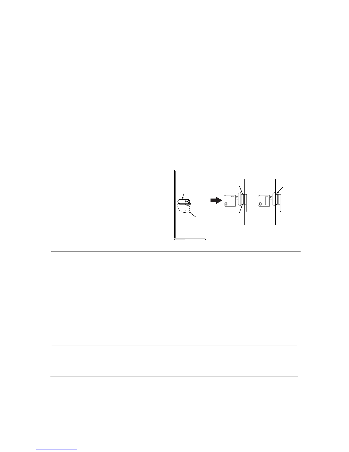
2. Remove cabinet door, then remove the lock
knockout from the door. Insert the key into
the lock.
3. Position the lock in the hole, making
certain that the latch will make contact
with the latch bracket when the door is
closed. When correctly positioned, push the
lock until it is held securely by its snap
tabs.
Mounting the PC Board
NOTE: The door of the metal cabinet may be
removed to make it easier to install the PC
board. Remove the door as follows:
1. With the cabinet laying on a flat surface,
swing open the door to its full-open position.
2. Slide the door out of its retaining slots in
the cabinet and store in a safe place.
3. Remove standoff (part number K0380) from
the hardware bag and insert it into the
square hole in the back of the cabinet so
that it will align behind the lower left
mounting hole in the PC board.
Notes
• The cabinet can be closed and secured without a
lock by using 2 screws in the cover's edge.
CHECK
POSITION
LOCKED
CABINET DOOR
UNLOCKED
BOTTOM
PUSH
SNAP
TAB
ADEMCO
SNAP
TAB
ADEMCO
STEP 2STEP 1
PUSH
ON LOCK
UNTIL IT
IS SEATED
SECURELY
Figure 1. Installing the Cabinet Lock
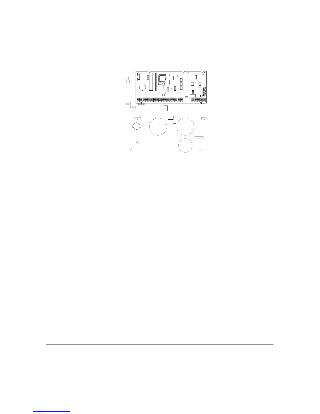
4. Insert top of circuit board into slots at top of
cabinet. Make sure that circuit board rests in
slots as indicated in the diagram shown below.
5. Swing base of circuit board onto the raised
cabinet tab and standoff.
6. Secure the sides of the PC board to the
enclosure using the 2 screws provided.
Notes
• Before installing the cabinet's contents, remove
the metal cabinet knockouts required for wiring
entry. Do not remove the knockouts after the
circuit board has been installed.
cab_lock_snap-001-V0
2-1
Installation and Setup Guide
1 3 4 5 6 7 8 9 10 11 12 13 14 15 16 17 21 22 23 25
Figure 2. Mounting the PC Board
V12D-001-V0
2-2
Wiring to Keypads
1. Connect keypads to the control’s keypad
terminals as shown on the Summary of
Connections diagram.
Determine wire size using the Wiring Run
Chart below.
2. Set keypad addresses. Refer to the address
setting instructions included with the
keypads and set each keypad device
address according to the chart at right.
3. Program the keypad addresses, partition
assignments and sound options in data
fields *190-*196.
NOTE: Each keypad must be assigned a
unique address, starting at address 16.
Keypads programmed with the same
address will give unpredictable results.
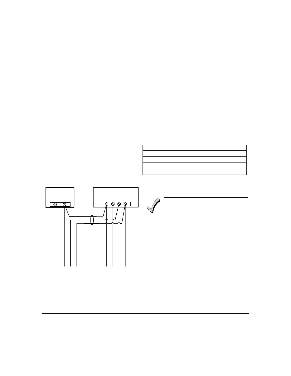
Supplementary Power (optional)
1. Connect as shown. Be sure to connect the
negative (–) terminal on the power supply
unit to terminal 4
(AUX –) on the control.
SUPPLEMENTARY
POWER SUPPLY
+
–
IMPORTANT:
MAKE THESE
CONNECTIONS
DIRECTLY TO
TERMINALS AS
CONTROL TERMINAL STRIP
SCREW
SHOWN.
AUX. DATA
AUX.
IN
+
–
456 7
DATA
OUT
Mounting and Wiring the Control
Notes
• Typical Fixed-Word Display:
6128RF/6148/6150/6150RF/6150V
• Typical Alpha Display: 6160/6160V/6160RF/6164
• The system supports up to 8 keypads, which can
be assigned to partitions in any combination
(see program fields *190-*196).
• For single 4-wire runs, determine the current
drain of all units, then refer to the Wiring Run
chart to determine the maximum length that can
be safely used for each wire size.
• Use supplementary power if the control’s aux.
power load for all devices exceeds 600mA.
Suggested power supply: AD12612
Keypad Addresses
Keypad Address Keypad Address
no. 1 16** no. 5 20
no. 2 17 no. 6 21
no. 3 18 no. 7 22
no. 4 19 no. 8 23
** The first keypad is address 16, which is always
enabled and set for partition 1 with all sounds on.
Keypads powered from supplies that do
not have a backup battery will not
function if AC mains power is lost. Make
sure to power at least one keypad in
each partition from the control’s auxiliary
power output.
TO KEYPAD RED POWER WIRE (V+)
TO KEYPAD BLK GROUND WIRE (V-)
TO KEYPAD YEL DATA WIRE (<)
TO KEYPAD GRN DATA WIRE (>)
Figure 3. Using a Supplementary Power
Supply
TO KEYPAD BLK GROUND WIRE (V-)
TO KEYPAD RED POWER WIRE (V+)
TO KEYPAD GRN DATA WIRE (>)
TO KEYPAD YEL DATA WIRE (<)
pwr_sup_conn-008-V0
2-3
Installation and Setup Guide
Wiring Run Chart For Devices* Drawing Aux Power From The Control (12V+ & 12V–)
Wire
TOTAL CURRENT DRAIN OF ALL DEVICES CONNECTED TO A SINGLE WIRE RUN
Size 50 mA or less 100 mA 300 mA 500 mA 600 mA
0.6mm O.D. 152m 76m 24m 15m 13m
0.8mm O.D. 228.6m 116m 40m 24m 20m
1mm O.D. 396m 198m 67m 40m 35m
1.2mm O.D. 457m 305m 100m 70m 52m
* Includes Keypads, RF Receivers, Zone Expander/Relay Units, or TeleCommand Phone Module.
Maximum wire lengths for any device that is wired directly to the control can also be determined from the Wiring Run
Chart, based on the current drain of that device alone
.
The length of all wire runs for all partitions combined must not exceed 457m when unshielded quad conductor cable
is used (228m if shielded/screened cable is used). This restriction is due to the capacitive effect on the data lines
when quad cable is used.
Sounder (Siren) Connections
1. Make sounder connections to alarm output terminals 3
(+) and 4 (–).
For supervised output, continue with steps 2 and 3.
2. Cut the red Siren Supervision Jumper located above
terminals 2 and 3 on the control board.
3. Connect a 2k ohm resistor across the terminals of the
last sounder.
TERMINALS ON
CONTROL BOARD
EXTERNAL ALARM
SOUNDER
Notes
• The 12VDC sounder output activates
when an alarm occurs.
• Total current drain from this output
cannot exceed 2 amps (going beyond 2
amps will overload the power supply,
or may cause the electronic circuit
protecting the sounder output to
activate).
• You must install a battery, since the
battery supplies this current.
• Do NOT perform steps 2 and 3 if using
a self-activated siren.
ALARM
OUTPUT
TERMINALS
_
4
+
3
_
+
OBSERVE
POLARITY
2000
OHM
EOL
RESISTOR
2
CUT RED JUMPER ON CONTROL
BOARD TO ENABLE SIREN
(SOUNDER) SUPERVISION.
Figure 4. Sounder Wiring (Supervised)
IF SIREN SUPERVISION IS ENABLED
(RED JUMPER ON CONTROL BOARD IS CUT)
CONNECT A 2000 OHM RESISTOR ACROSS
THE EXTERNAL SOUNDER AS SHOWN BY
THE DOTTED LINE.
DO NOT CONNECT THE RESISTOR AT THE
ALARM OUTPUT TERMINALS THEMSELVES!
V48sounder-001-V0
2-4

Wiring the AC Transformer
Transformer:
Connect the Transformer to terminals 1 and 2 on the
control board. See wiring table at right for wire size to
use.
Use wired-in or plug-in 110 (e.g. 1321)/220VAC
transformer, with 16.5VAC, 25VA output.
Mounting and Wiring the Control
Notes
• Use caution when wiring the
transformer to the control to guard
against blowing the transformer fuse
(the fuse is non-replaceable).
• Wiring to the AC transformer must
not exceed 76m using 1.2mm O.D.
wire. The voltage reading between
terminals 1 and 2 of the control must
not fall below 16.5VAC or an “AC
LOSS” message will be displayed.
• Do not connect to AC mains power
while making any wiring connections
to the control. As a safety precaution,
always power down the control when
making such connections.
Wiring Table
Distance from control Wire Gauge
Up to 15m 0.8mm O.D.
15-30m 1.0mm O.D.
30-76m 1.2mm O.D.
2-5

Installation and Setup Guide
Backup Battery
1. Place the 12-volt backup battery in the cabinet.
2. After all connections to the control are completed
and AC mains power has been applied, connect the
red and black flying leads on the control board to the
battery. Do not attach these leads to the battery
terminals until all connections are completed.
Notes
IMPORTANT: The panel will not power
up initially on battery power only. You
must plug the transformer in first, and
then connect the battery.
Battery Saver Feature: The battery will disconnect
from the system after its voltage decreases below
9VDC. This assists the control panel in recharging the
battery when AC is restored.
Earth Ground
Metal Cold Water Pipe or Earth Ground Rod:
Use a non-corrosive metal strap (copper is
recommended) firmly secured to the pipe/rod to which
the ground lead is electrically connected and secured.
Notes
• This product has been designed and tested to ensure
its resistance to damage from generally expected levels
of lightning and electrical discharge, and does not
normally require an earth ground.
• If an earth ground is desired for
additional protection in areas of severe
electrical activity, terminal 25 on the
control board, or the cabinet, may be
used as the ground connection point.
The examples of good earth grounds
listed at the left are available at some
installations.
AUXILIARY DEVICE CURRENT DRAIN WORKSHEET
DEVICE CURRENT # UNITS TOTAL CURRENT
6128RF Keypad/Transceiver 90mA standby/120mA alarm
6150RF Keypad/Transceiver 80mA standby/105mA alarm
6160RF Keypad/Transceiver 50mA standby/150mA alarm
6148 Fixed-Word Keypad 30mA standby/55mA alarm
6164 Keypad w/4-Zone Expander
and Relay
5881RF Receiver 35mA
5883 RF Transceiver 80mA
5882EU/5882EUH Transceivers 60mA nominal, 85mA peak
4219 Zone Expander 35mA
4204 Relay Unit
4229 Zone Expander/Relay Unit
TeleCommand 55mA (standby)
*
*
*If using wired devices such as PIRs or Dual Tecs, refer to the specifications for that particular unit's
current drain.
‡
Figures are for relays OFF/relays ON.
115mA standby/190mA alarm
15/180mA‡
35/100mA‡
119mA (local phone)
85mA (remote phone)
(Current available from Aux. terminals = 600 mA max.)
TOTAL =
2-6
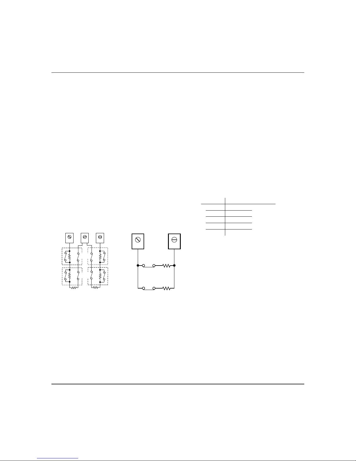
Basic Wired Zones
Normally Open Zones/Normally Open EOLR Zones
1. Connect open circuit devices in parallel across the
loop; for EOLR zones, connect the EOLR across the
loop wires at the last device.
2. Enable normally open/EOLR zones using Zone
Programming mode, “Hardwire Type” prompt.
Normally Closed Zones/Normally Closed EOLR Zones
1. Connect closed circuit devices in series in the high (+)
side of the loop; for EOLR zones, connect the EOLR in
series following the last device.
2. Enable normally closed/EOLR zones using Zone
Programming mode, “Hardwire Type” prompt..
Double-Balanced: Connections as shown (resistors
provided for one device in selected models); maximum of
8 sensors on each double-balanced zone.
IMPORTANT: Double-balanced zones provide unique
tamper signalling on the same 2 wires used for alarm
signalling, and should be used as burglary or emergency
zones only. Do not use double-balanced zones as fire
zones.
Zone Doubling: Connections as shown (resistors
provided).
Double Balanced Zones Zone Doubling
12 13
TAMPER
2k
CONTACTS
TAMPER
2k
CONTACTS
2k
ZONE 3
14
10 11
2k
2k
ZONE 2
ZONE 10
2k
ZONE 4
zone-002-V0
6.2k
Figure 5. Configuring Zones
3k
zone-004-V0
Mounting and Wiring the Control
Notes
• EOLR: If the EOLR is not at the end of
the loop, the zone is not properly
supervised and the system may not
respond to an “open” on the zone.
• Zone 1 is intended only for EOLR
usage.
Zone Doubling:
This feature provides two unique zone
identifications for normally closed
sensors connected to each basic wired
zone (but does not increase the total
number of zones supported by the
control). Do not use zone doubling for
fire zones. If enabled (Zone
Programming mode, “Hardwire Type”
prompt, option “3”), basic wired zones
are automatically paired as follows:
Zone Paired with zone
2 10
3 11
4 12
5 13
6 14
NOTE: A short across the EOL (i.e., at
terminal) on either zone of a zonedoubled pair or on a double-balanced
zone causes a tamper condition
(displayed at keypad as CHECK).
2-7
Installation and Setup Guide
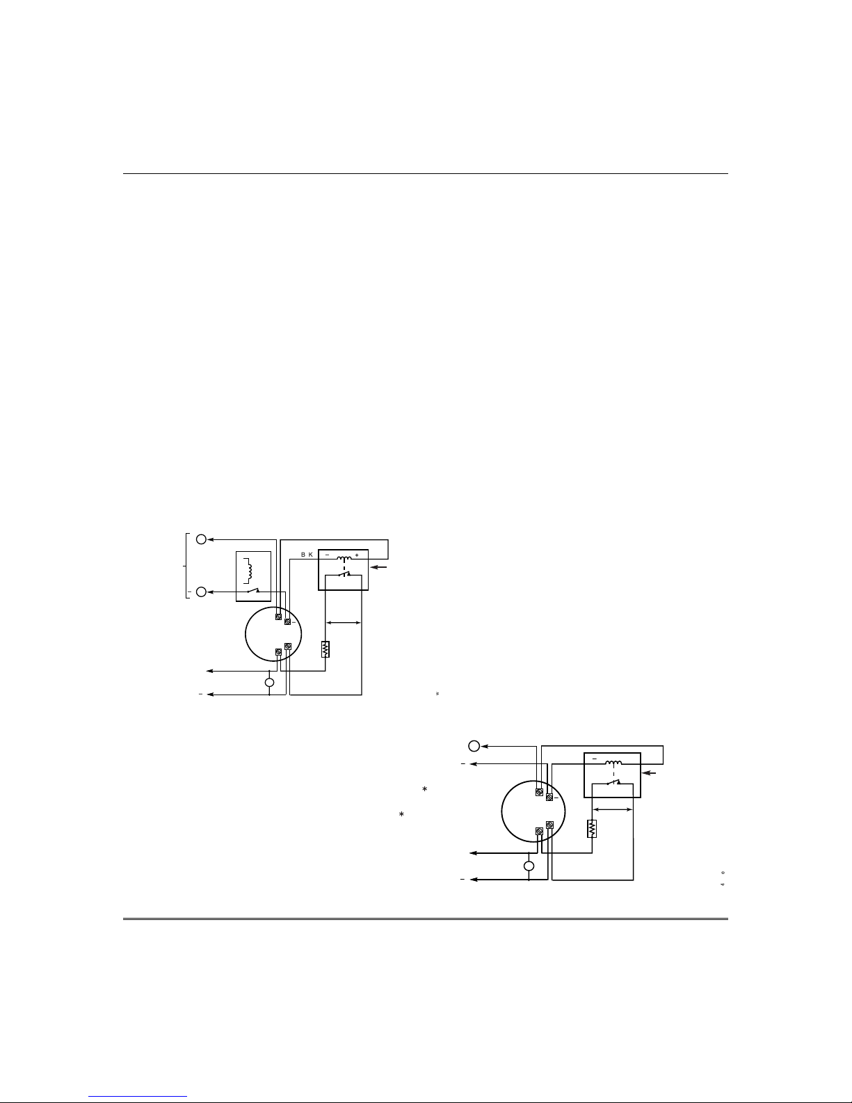
Smoke Detectors
2-Wire Smoke Detectors
1. Connect up to sixteen 2-wire smoke detectors across
zone 1 terminals 8 (+) and 9 (-) as shown in the
Summary of Connections diagram. Observe proper
polarity when connecting the detectors.
2. Connect an EOL resistor across the loop wires at the
last detector.
4-Wire Smoke Detectors
3. Connect 4-wire smoke detectors (up to 16, depending
on detector current drain) to any zone from 2-8 as
shown on the next page. This control does not
automatically reset power to 4-wire smoke detector
zones, so you must use a relay (e.g., 4204, 4229), or
on-board trigger 17 to reset power (also required for
fire verification). Do this by programming the
designated relay/trigger as zone type 54 (fire zone
reset); see On-Board Trigger section for other
information.
5
AUX PWR
OUTPUT
TERMINALS
CONTACT OPENS
MOMENTARILY UPON
FIRE ALARM RESET
TO ZONE TERM. ( )
TO ZONE TERM. ( )
+
_
(FIRE ZONE
4
+
_
PROGRAM
RELAY
AS ZONE
TYPE 54
RESET)
RELAY
N.C.
OR COMBUSTION
HEAT
DETECTOR
4-Wire Smoke Detector Using Relay for Power Reset
Figure 6. 4-Wire Smoke Detector Connections
_
+
4-WIRE SMOKE
DETECTOR
BLK
_
2000
OHMS
EOLR
+
N.O.
VIOLET
RED
EOL
POWER
SUPERVISION
RELAY MODULE
A77-716B.
USE N.O.
CONTACT,
WHICH CLOSES
WHEN POWER
IS APPLIED.
AUX PWR
TO OUTPUT 17
PROGRAM OUTPUT 17
FOR "OUT NORM
LOW" = YES IN 79 MENU
MODE AND AS ZONE
TYPE 54 IN
80 MENU MODE
TO ZONE TERM. ( )
TO ZONE TERM. ( )
4-Wire Smoke Detector Using Output 17 for Power Reset
4_wiresmk-007-V0
+
( )
_
( )
+
_
Notes
•••• Fire Verification (zone type 16):
The control panel will “verify” a fire
alarm by resetting the smoke
detectors after the first alarm trigger,
and then waiting 90 seconds for a
second alarm trigger. If the smoke
detector does not trigger again, the
control will disregard the first trigger,
and no alarm signal will occur. This
feature eliminates false alarms from
smoke detectors due to electrical or
physical transients.
• The zone 1 alarm current supports
only one smoke detector in the
alarmed state.
• Do not use 4-wire smoke detectors on
zone 1.
• Maximum current for trigger 17
output for 4-wire smoke detectors is
100mA.
5
DETECTOR
+
4-WIRE SMOKE
OR COMBUSTION
DETECTOR
HEAT
_
BLK
2000
OHMS
EOLR
_
N.O.
VIOLET
+
RED
EOL
POWER
SUPERVISION
RELAY MODULE
A77-716B.
USE N.O.
CONTACT,
WHICH CLOSES
WHEN POWER
IS APPLIED.
4_wiresmk-008-V0
2-8
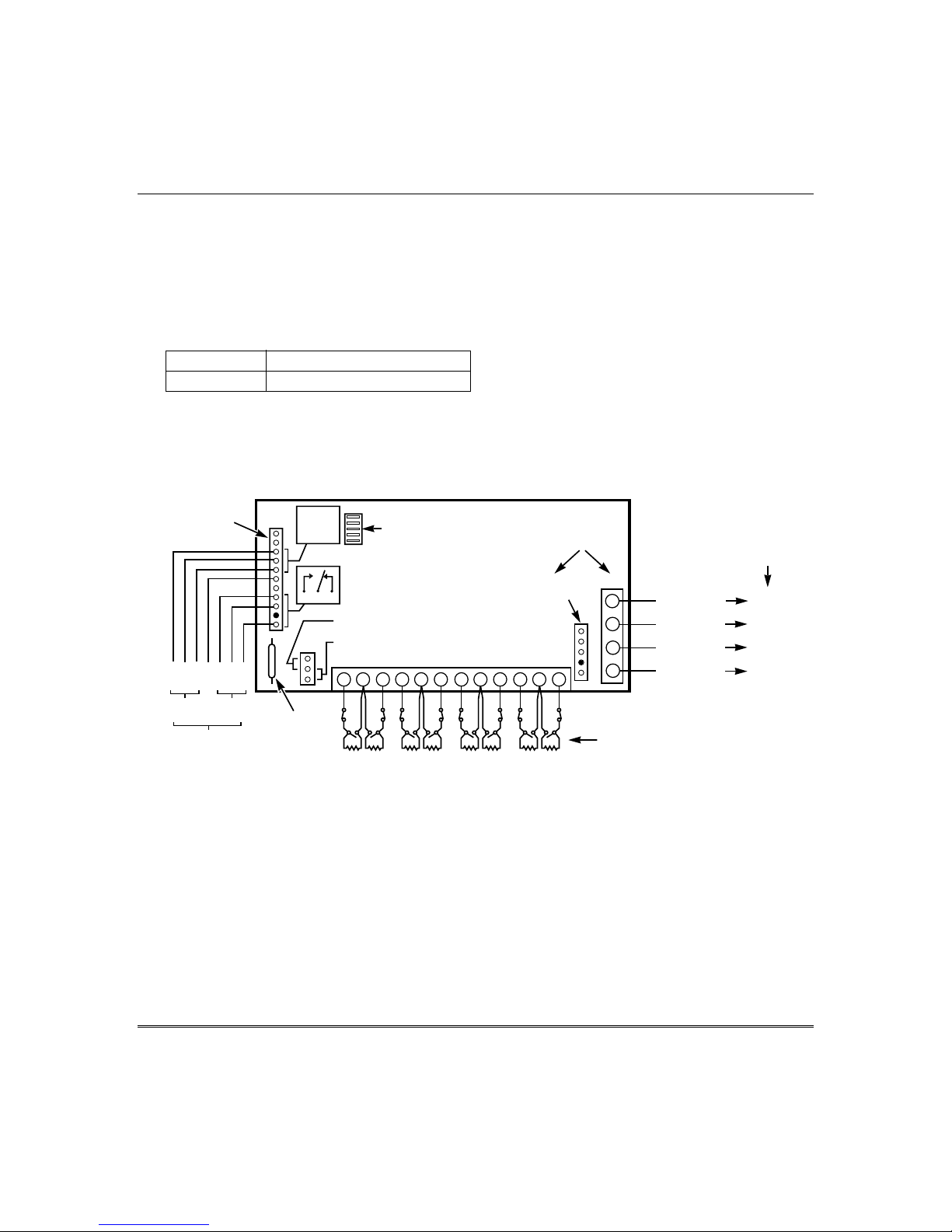
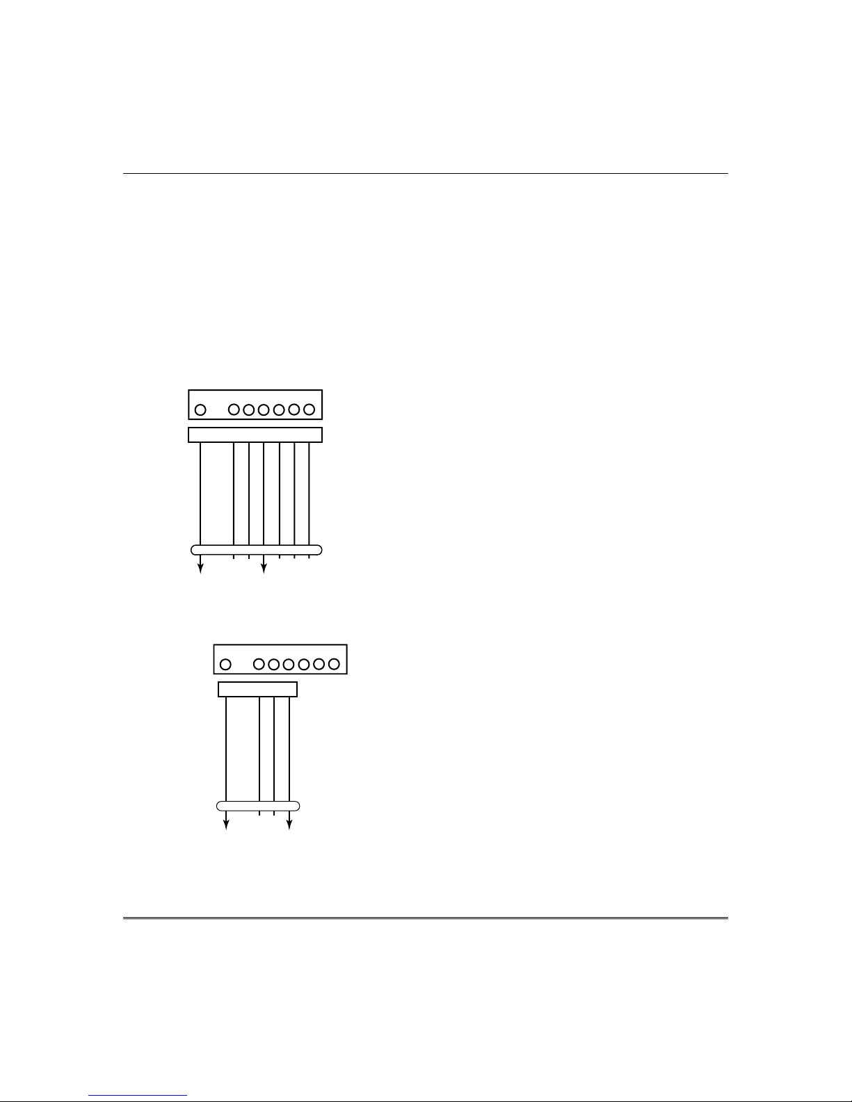
4219/4229 Expansion Zones
1. Connect each module to the control’s keypad
terminals.
2. Assign the module a device address of 08
using its DIP switches. The device address
determines the zone numbers being used, as
shown below.
Expander Module Addresses
Zones… Device Address…
17-24 08
3. Connect sensors to the module’s loops.
4. If using relays with the 4229, connect the
desired field wiring to the unit's relay
contact terminals.
RELAY
CONNECTOR
VIO
BLK
GRY
WHT
NONCC
RLY
2
RELAYS OFF
YEL
GND
ORG
NONCC
RLY
1
BRN
RELAY
NO C NC
REED
(TAMPER)
SWITCH
ZONES
2
DIP SWITCH
FOR SETTING ADDRESS
AND ZONE "A" RESPONSE
RELAY
1
TAMPER JUMPER POSITION
4229 IN CABINET
(NOT TAMPER)
4229 REMOTE
(TAMPER PROTECTED)
2
1
3
B
A
4 6
5
C
D
Mounting and Wiring the Control
Notes
• Supports up to 8 expansion zones (NO or NC)
using 4219/4229 Zone Expander Modules as
follows:
• Use 1000 ohm end-of-line resistors at the end
of loops connected to the 4219/4229 modules.
(End-of line resistors used on the control
terminals are 2000 ohms.)
• Expansion zones have normal response time
(400–500 msec), except zone connected to each
module’s loop “A,” which can be set for fast
response† (10–15 msec).
† Do not use fast response in Western Europe;
fast response is not permitted by
EN50131-1/prEN50131-3.
4229
EITHER OR BOTH CAN BE USED
4-PIN CONSOLE PLUG
TB1
8
9
7
E
10
F
12
11
GH
TB2
GRN
BLK
RED
YEL
DATA OUT (>)
TO CONTROL
(–) GROUND
(+) 12VDC
DATA IN (<)
FROM
CONTROL
4
3
4
3
2
2
1
1
TERMINATE EACH
PROGRAMMED ZONE
WITH 1000 OHM (1K)
END-OF-LINE RESISTOR
(EACH ZONE'S MAX.
LOOP RESISTANCE
300 OHMS + EOL)
TERMINALS ON
CONTROL PANEL
(TERM 6)
(TERM 4)
(TERM 5)
(TERM 7)
Figure 7. Wiring Connections, 4219 & 4229 (4229 shown)
4229-002-V0
2-9
Installation and Setup Guide
-
)
6164 Keypad Expansion Zones
1. Connect each keypad to the control’s keypad
terminals.
2. Using the keypad’s program mode, assign the
keypad a unique keypad address (16-23), and
assign a device address of 08 which provides
expansion zones 17-20.
3. Connect sensors to the keypad’s zone
terminals.
4. If using the keypad relay, connect the desired
field wiring to the keypad's relay contact
terminals.
See 6164 Keypad Instructions for other
mounting, wiring, and programming
information.
Notes
• Each 6164 keypad supports up to 4 wired
expansion EOLR or double-balanced zones
and one relay output.
• Use 2000 ohm end-of-line resistors at the
end of loops connected to the 6164 keypads.
• Enter 6164 keypad program mode by
pressing and holding down both the [1] and
[3] keys within 60 seconds of power up.
• Enable the keypad addresses using data
fields *191-*196 as required.
• Program keypad zones using *56 Menu
mode. Keypad zones 1-4 correspond to the
respective groups of zones shown in the
chart at left, where keypad zone 1 is the
lowest zone number in each group.
DOUBLE BALANCED
2K
2K
TAMPER
CONTACTS
OPTIONAL
2K
N.O.
CONVENTIONAL
EOLR
[Y] DATA IN (<
[+] +12VDC IN
2-10
TAMPER
2K
CONTACTS
N.O.
C.
N.C.
Z1
Z2
(Z1
&
Z2)
N.C.
Y +
Z4
Z3
(Z3
&
Z4)
[-] GROUND (
[G] DATA OUT
G
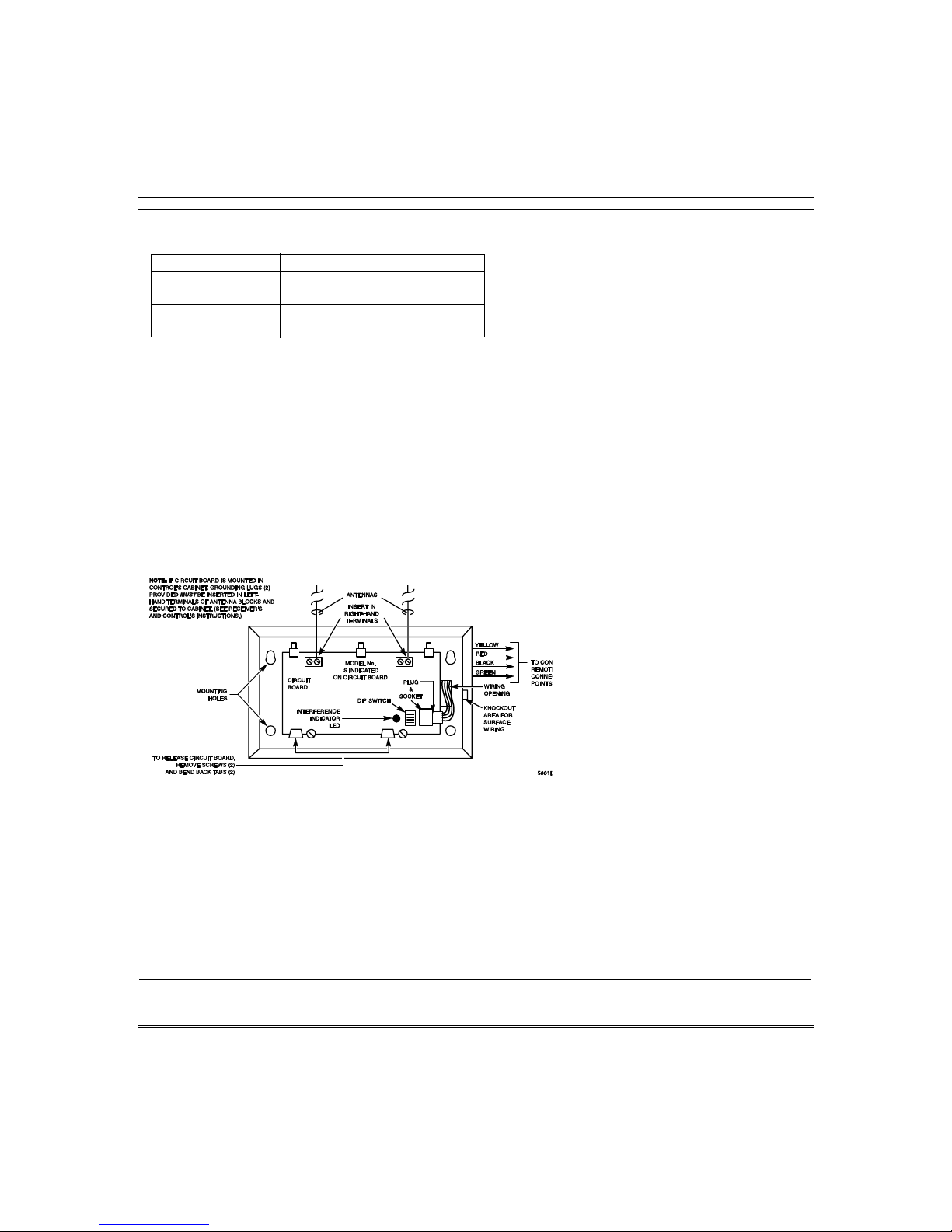
Installing the RF Receiver
Use one of the following receivers:
RF Receiver Number of Zones
5881ENL up to 8 (including keyfob
buttons)
5881ENM up to 16 (including keyfob
1. Set Device Address to “00” as described in its
instructions (set all switches to the right, “off”
position).
2. Mount the receiver, noting that the RF receiver
can detect signals from transmitters within a
nominal range of 67m.
3. Connect the receiver's wire harness to the
control's keypad terminals. Plug the connector
at the other end of the harness into the
receiver. Refer to the installation instructions
provided with the receiver for further
installation procedures regarding antenna
mounting, etc.
buttons)
Mounting and Wiring the Control
Notes
• The receiver is supervised and a trouble
report is sent (“CHECK 100” displayed) if
communication between the panel and
receiver is interrupted, or if no valid RF
signals from at least one supervised
transmitter are received within 12 hours.
• Only one receiver can be installed in a system.
If the receiver is mounted remotely:
• Place the RF receiver in a high, centrally
located area for best reception.
• Do not locate the receiver or transmitters on
or near metal objects. This will decrease
range and/or block transmissions.
• Do not locate the RF receiver in an area of
high RF interference (indicated by frequent
or prolonged lighting of the LED in the
receiver; random flicker is OK).
• Do not locate RF receiver closer than 3m
from any keypads to avoid interference from
the microprocessors in those units.
Figure 8. 5881EN RF Receiver (cover removed)
Installing a 5800TM Module
1. Mount the 5800TM next to the RF receiver
(between one and two feet from the receiver’s
antennas) using its accompanying mounting
bracket. Do not install within the control
cabinet.
2. Connect the 5800TM to the control panel’s
keypad connection terminals as shown on the
Summary of Connections diagram and set to
address 28.
WIRELESS ZONE NUMBERS
transmitter zones 9-24
button or transmitter zones 49-64
Notes
• Use this module only in 345Hz RF systems
and if you are using one or more wireless bidirectional keypads or keyfob; 5800TM is not
necessary if using a Transceiver (e.g., 5883).
• The 5800TM must be set to address 28 (cut
red-W1 jumper).
• The 5800TM can be used in partition 1 only.
• For additional information regarding the
5800TM, refer to the 5800TM’s instructions.
2-11

Installation and Setup Guide
s
m
K
Installing the Transmitters
1. To be sure reception of the transmitter's signal
at the proposed mounting location is adequate,
perform a Go/No Go Test (see the Testing the
System section).
2. Install transmitters in accordance with the
instructions provided with each.
3. Set 5827, 5827BD, 5804BD wireless keypads to
the programmed House ID (field *24), using its
DIP switches (5827) or follow the instructions
provided with the device.
Notes
• Refer to the table of compatible devices at
the back of this manual.
• Supervised transmitters† send check-in signal
to the receiver at 70-90 minute intervals. If at
least one check-in message is not received fro
each transmitter within a 12-hour period, the
“missing” transmitter number(s) and “CHEC
is displayed.
†
Hand-held transmitters (e.g., 5802, 5802CP, 5804,
5804BD, 5827, 5827BD) do not send check-in
signals.
Transmitter Battery Life
• See Wireless Transmitter paragraph in the Limitations of This Alarm System statement located
at the end of this manual for information on transmitter battery life.
• Some transmitters (e.g., 5802 and 5802CP) contain long-life but non-replaceable batteries, and no
battery installation is required. At the end of their life, the complete unit must be replaced (and a
new serial number enrolled by the control).
• Button-type transmitters (such as 5801, 5802, and 5802CP) should be periodically tested for
battery life.
• The 5802EU, 5802MN, 5802MN2, 5804EU, and 5804 Button Transmitters have replaceable
batteries.
Do not install batteries in wireless transmitters until you are ready to enroll during system
programming. After enrolling, batteries need not be removed.
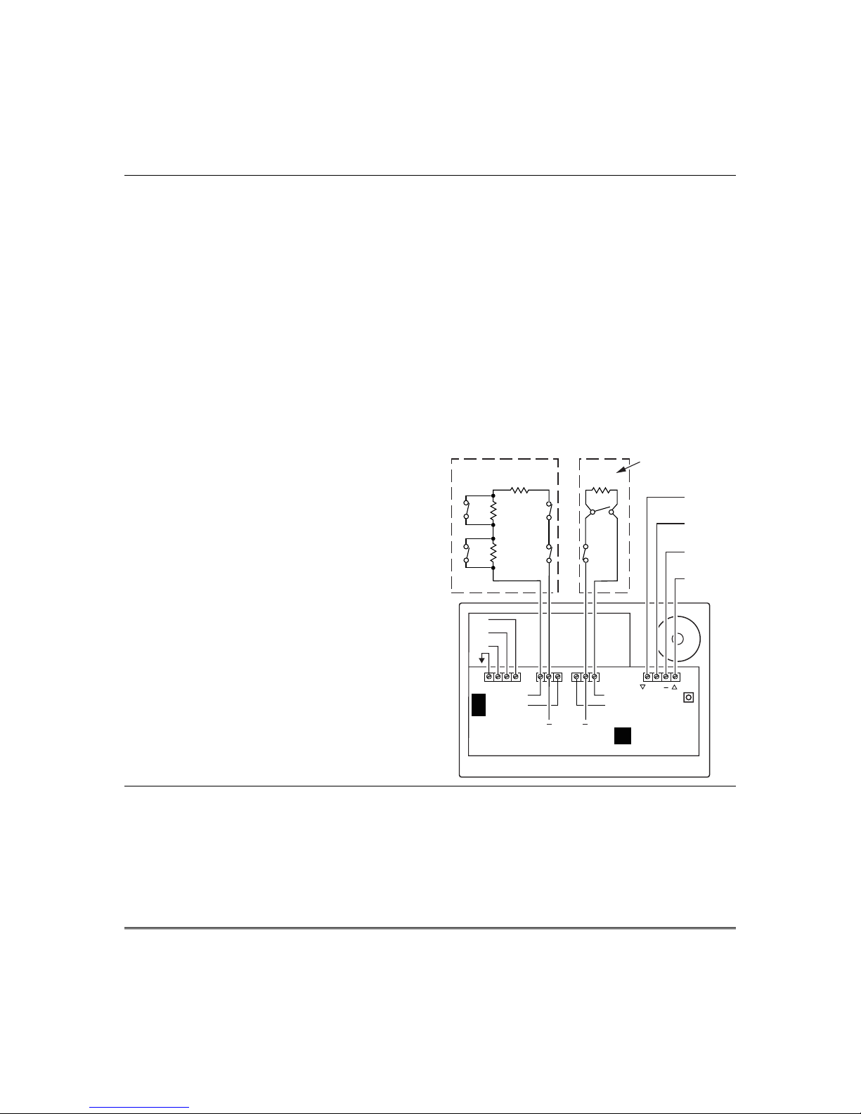
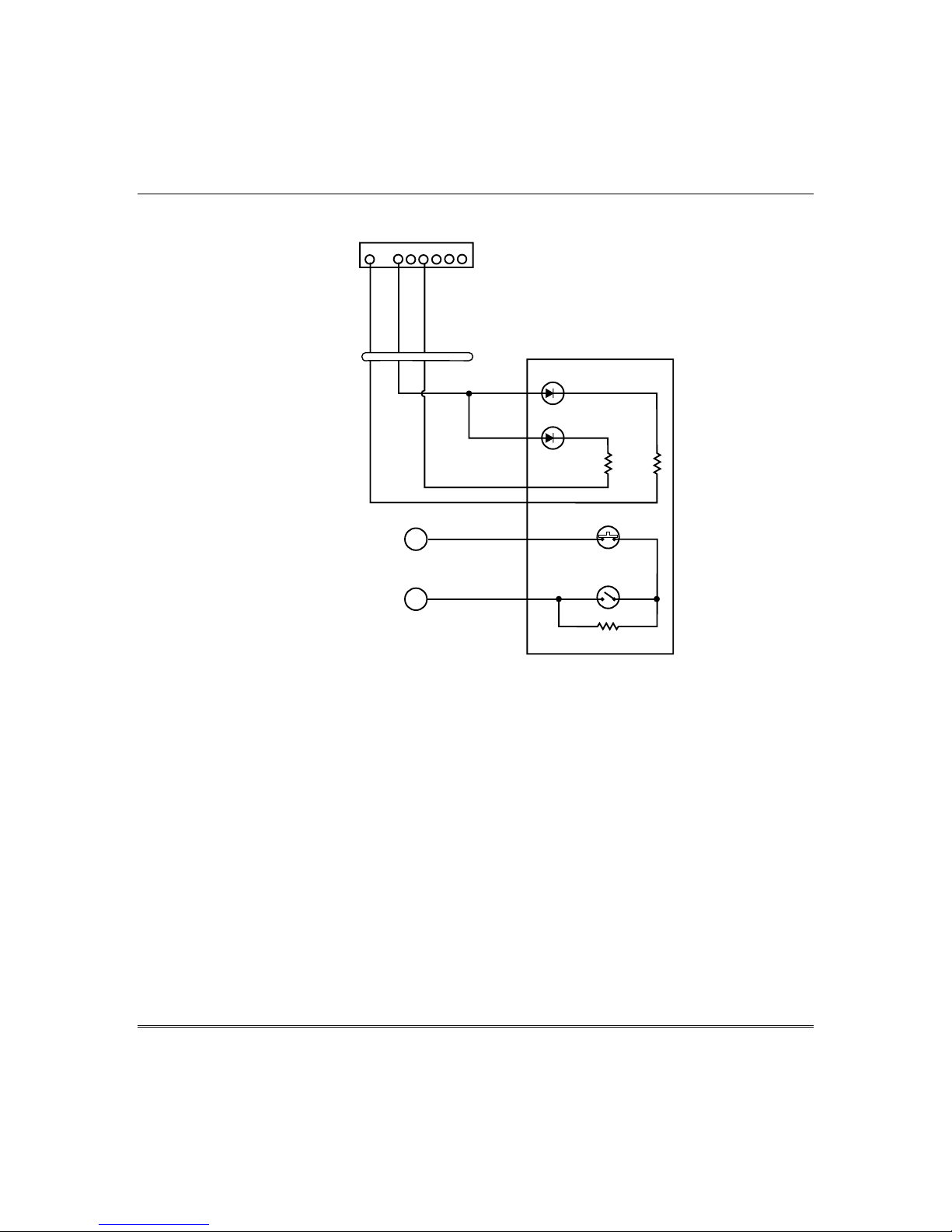
Installing a Keyswitch
1. Connect the 4146 keyswitch's normally open
momentary switch to a zone’s terminals
(zones 2-8). Remove the 2000 ohm EOL
resistor if connected across the selected zone.
2. Using a standard keypad cable as shown:
Connect the yellow and white keyswitch wires
to trigger connector pin 3 (+12V).
Connect the Red and Green LED wires to the
appropriate output 17/output 18 trigger
connector pins.
3. Connect a 2000 ohm EOL resistor across the
momentary switch.
4. You can wire an optional closed-circuit
tamper switch (model 112) in series with the
zone. If the switchplate is then removed from
the wall, the tamper will open, disabling
keyswitch operation until the system is next
disarmed from the keypad.
If the tamper is opened when the system is
Notes
• Use 4146 keyswitch or any normally open
keyswitch.
• Use only one keyswitch per partition.
• If using a keyswitch in more than one partition,
you must use relays (not the on-board triggers)
for the Red/Green LED functions (step 2).
• When using a keyswitch, the zone it is
connected to is no longer available for use as a
protective zone.
• Use *56 Menu mode to program the keyswitch
zone and assign it zone type 77.
• Use *80 Menu mode to program the LED
functions: program outputs 17 and 18 for
system operation zone type 78 (red LED)
and 79 (green LED) as appropriate (see
Output Device Programming section).
armed, an alarm will occur.
2-12
Mounting and Wiring the Control
8-PIN TRIGGER CONNECTOR
1345678
KEY
(RED)
(YELLOW)
OUTPUT 17
(GREEN)
+12 AUX.
OUTPUT 18
11
TYPICAL ZONE
ON CONTROL
BOARD
10
4-WIRE
CABLE
YELLOW
WHITE
BLACK
BROWN
BLUE
RED
(ARMED)
RED
(READY)
GREEN
4146 KEYSWITCH
820
ohms
TAMPER
SWITCH (N. C.)
LOCK
SWITCH (N. O.)
820
ohms
BROWN
BLUE
EOLR
(use appropriate value)
00-trigcon-004-V2
Figure 9. Keyswitch Wiring Connections
2-13

Installation and Setup Guide
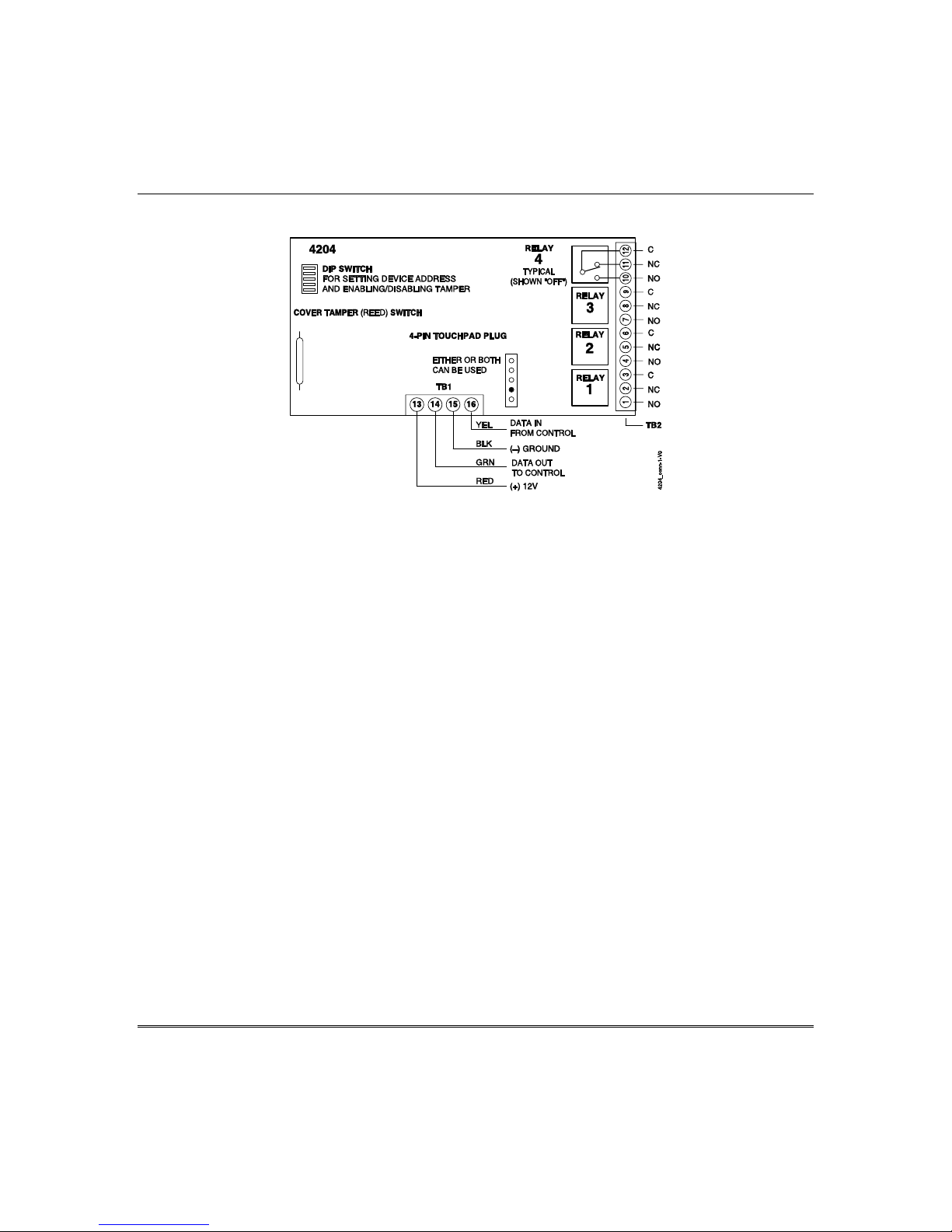
Connecting Relay Modules
1. Mount either remotely or in the control panel.
2. Connect to control’s keypad terminals using the
connector harness supplied with the module.
Use standard 4-conductor twisted cable for long
wiring runs.
3. Set the module’s device address according to
the table at right.
4. Connect the desired field wiring to the unit's
relay contact terminals.
Notes
• Use 4204/4229 modules or 6164 keypad.
• Supervision: 4204/4229 modules and 6164
keypad are supervised against removal. The
module’s device address is displayed as
follows if a module is disconnected from the
control’s terminals, or if the module cover is
removed and the tamper jumper is installed:
Alpha: CHECK xx Wire Expansion
FAULT xx Wire Expansion
TAMPER xx Wire Expansion
ALARM xx Wire Expansion
Fixed-Glass: lxx (or 91 if field *199 set for 2-digit
display)
where “xx is the module’s address.
• If communication/tamper failure occurs on a
device with zones wired to it, all zones on the
device will be displayed in their respective
partitions.
Relay Module Addresses
4204/6164
†
Address 4229/6164†† Address
2 13 (zn 17-24) 08
† Use these addresses if using only relays with
the 6164 and not its zones.
†† Use these addresses if using zone expansion
and relays with the 6164; supports only the
first four zones in parenthesis.
NOTE: You can not use a 4229 and 6164 in the
same system.
††† Not available if zone doubling used.
2-14
Mounting and Wiring the Control
Figure 10. 4204 Connections to Control
(4229 Module and 6164 Keypad is shown in the Expansion Zones sections on page 2-9)
2-15
Installation and Setup Guide
Powerline Carrier Devices
1. Install up to 4 powerline carrier devices (if no
relays are used) according to the instructions
included with each.
2. Connect the Powerline Interface Modulator
(XM10E) to the trigger pins as shown below.
3. Use Programming Mode to enter the device
house ID in data field*27, and enter the unit
code using *79 Output Device menu Mode.
8-PIN TRIGGER CONNECTOR
1345678
KEY
Notes
• When using Powerline Carrier devices, you
must use a Powerline Carrier Device
Modulator. It supplies signals from the
control panel through the premises AC
mains wiring to the Powerline Carrier
devices (which are plugged into AC outlets).
You can then make devices that are plugged
into Powerline Carrier devices perform
various functions in response to commands
you enter at the security system keypads.
(RED)
(ORANGE)
+12 AUX.
OUTPUT 17
(GREEN)
(YELLOW)
GND (-)
OUTPUT 18
(BLUE)
(PURPLE)
COM
DATA
(BLACK)
SYNC
SA4120XM-1 CABLE
(PART OF 4120TR)
SYNC
COM
DATA
XM10E Powerline Interface Connections
BLK
GRN
RED
YEL
XM10E
POWERLINE
INTERFACE
MODULATOR
1 2 3 4
MODULAR PHONE CORD (not supplied)
1 - BLACK
2 - RED
3 - GREEN
4 - YELLOW
00-trigcon-012-V0
2-16
On-Board Triggers
Connect field wiring to the desired trigger pin
on the 8-pin trigger connector centrally located
above the terminal strip.
• If using a Powerline Interface Modulator and
powerline carrier devices, use the
SA4120XM-1 cable (part of 4120TR Trigger
Cable). See previous Powerline Carrier
Device section.
• If only using the on-board triggers, you can
use a 4-wire cable (N4632-4, supplied with
the control) as shown below.
Figure 11. On-Board Trigger Connector with
SA4120XM-1 Cable for Use With X10 Powerline
8-PIN TRIGGER CONNECTOR
1345678
KEY
(RED)
(ORANGE)
+12 AUX.
OUTPUT 17
(GREEN)
(YELLOW)
GND (-)
OUTPUT 18
(BLUE)
(PURPLE)
COM
DATA
(BLACK)
SYNC
SA412OXM-1
CABLE
Interface Modulator
KEY
(RED)
(BLACK)
(GREEN)
8-PIN TRIGGER CONNECTOR
1345678
(YELLOW)
00-trigcon-003-V1
Mounting and Wiring the Control
Notes
• There are two on-board triggers that can
be used to activate output devices.
• These outputs are normally high, and go
low upon programmed condition.
• The outputs can be programmed for
inverted operation (normally low, go high)
using *79 Menu mode.
• Program these triggers using *80/*81
Menu modes as you would for any other
relay output.
• When using these outputs, note:
pin 1 = output number 17 (trigger 1):
15 ohms to ground when closed
(output low), open when off
(output high, normal default); can
be used to reset smoke detector
power (must set “output normal
low = yes” in *79 Menu mode, and
set for zone type 54, fire zone
reset, in *80 Menu mode); or can
support 12V relay module that
draws less than 100mA
pin 5 = output number 18 (trigger 2):
15 ohms to ground when closed
(output low); open when off
(output high, normal default); or
can support 12V relay module
• NOTE: Do not exceed 120mA combined
that draws less than 20mA.
current for both triggers. Doing so
can damage PC board components
and will void the system’s
warranty.
GND (-)
+12 AUX.
OUTPUT 17
Figure 12. On-Board Trigger Connector with
4-Wire Cable for Trigger Use Only
OUTPUT 18
4-WIRE
CABLE
00-trigcon-005-V2
2-17
Installation and Setup Guide
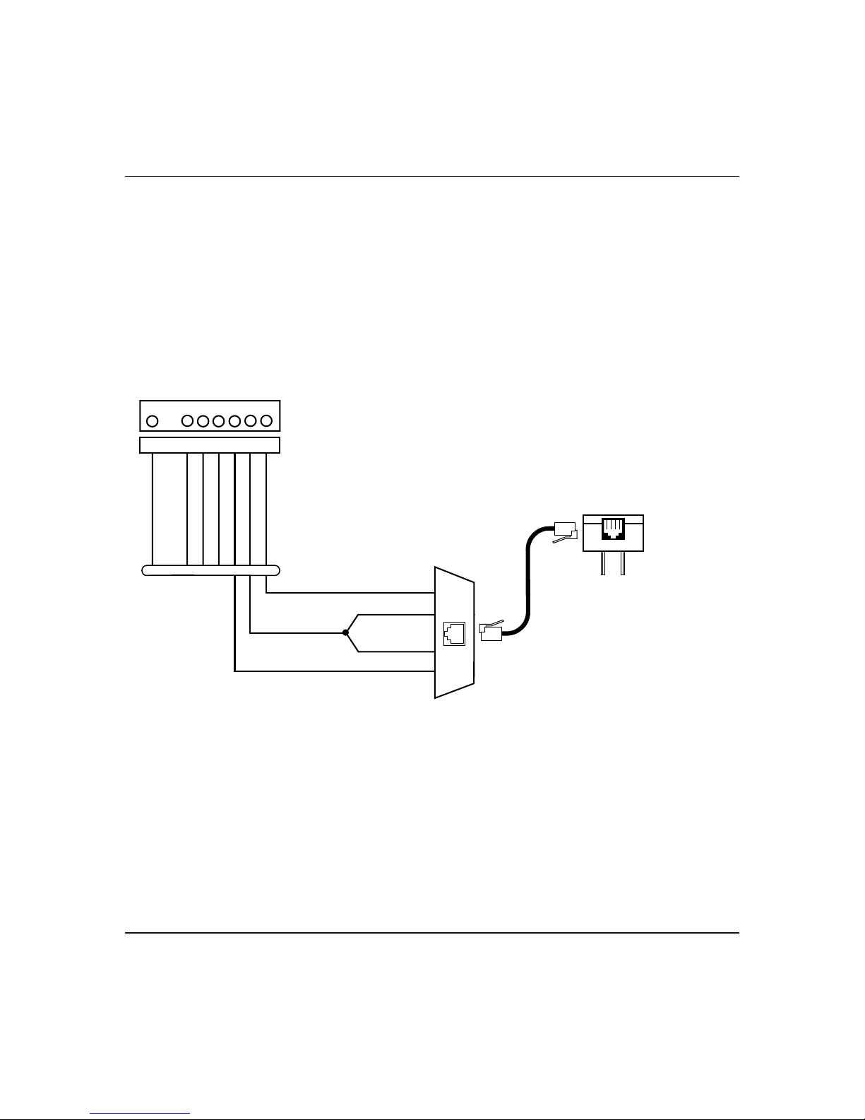
Phone Line Connections
Connect incoming phone line and handset wiring
to the main terminal block (via an RJ31X jack) as
shown in the Summary of Connections diagram at
the back of this manual. Wire colors represent the
colors of the cable to the RJ31X jack.
Alternative Communications Media
(ACM) Connections
Connect the data in/data out terminals and
voltage input terminals of the ACM to the
control's keypad connection points.
Set the ACM’s address to “03” following the
instructions provided with the ACM.
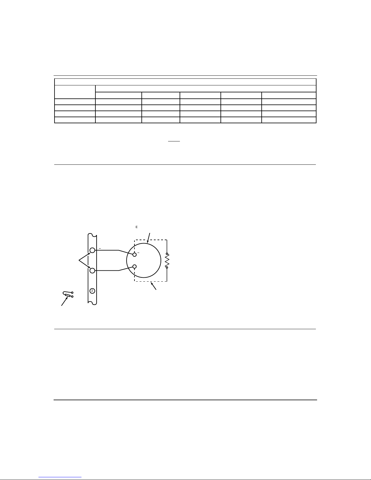
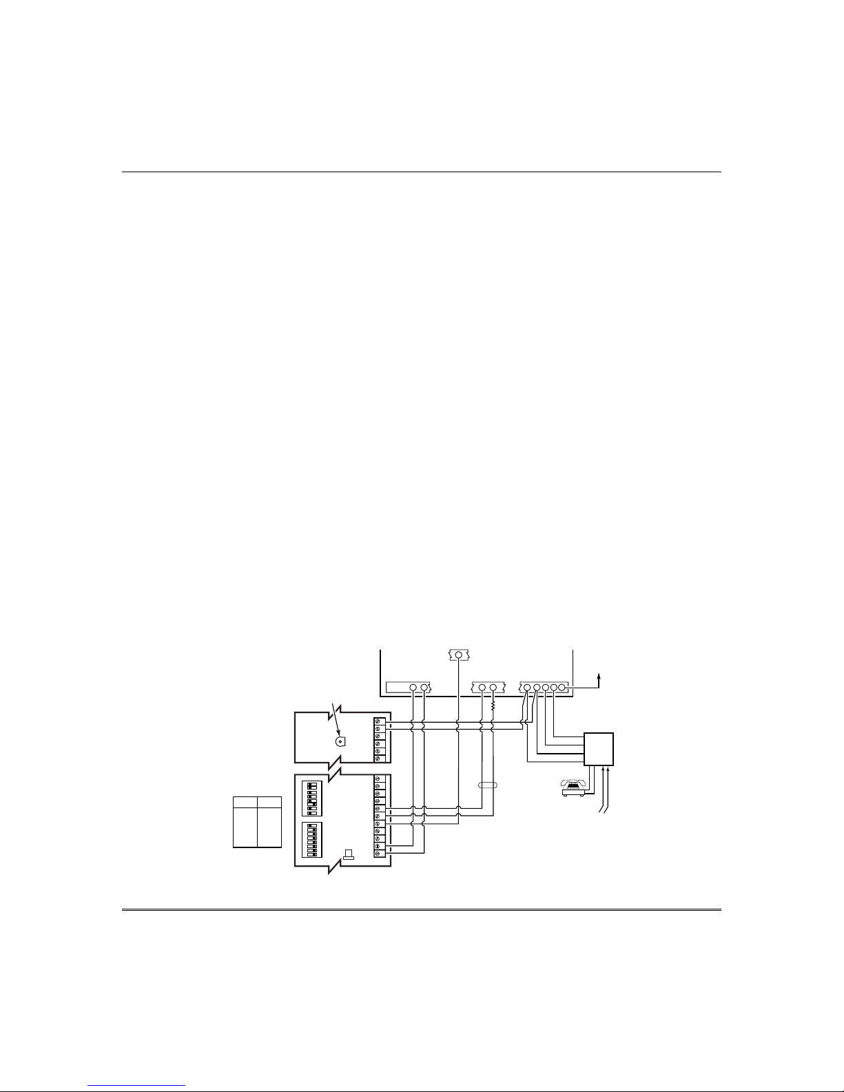
Audio Alarm Verification
Connections (AAV, “Listen-In”)
Refer to the connection diagram below.
Connections use one of the on-board triggers.
Suggested AAV Module:
ADEMCO UVS (shown) or Eagle 1250
UVCM
MODULE
NOTE:
REFER TO UVCM MODULE
INSTRUCTIONS FOR
CONNECTIONS TO AUDIO
SPEAKERS AND MICROPHONE.
SWITCH
SWITCH
BANK 2
BANK 1
1 = ON
1 = OFF
2 = ON
2 = OFF
3 = OFF
3 = OFF
4 = ON
4 = OFF
5 = ON
5 = OFF
6 = ON
6 = OFF
7 = ON
7 = OFF
8 = ON
8 = ON
ON ON
+12VDC IN
CONTROL
29 30 31 32 33 34
GND
1234567891011
AUXILIARY
AUDIO LEVEL
ADJUSTMENT
TRIM POT
SWITCH BANK 2
SWITCH BANK 1
12345678 1 2345678
FALLING VOICE TRIG
Figure 13. Connection of AAV Unit
Notes
• If you are using an Audio Alarm Verification
(AAV) unit, refer to Audio Alarm
Verification (AAV) section for special
wiring connections.
CAUTION: To reduce the risk of fire, use only
0.6mm O.D. or larger telecommunication line
cord for phone line connections.
Notes
• Use compatible ACMs (e.g., 7845i,
7845C/7835C [in Latin America], AI4164RS,
AI4164ETH).
Notes
• Set field *91 for AAV and program the
appropriate output (output 17 or 18) using
*80 Menu mode (select zone type “60”).
• For voice session monitoring, connect an
EOLR zone to UVCM module terminals 6 &
7, and program the zone as zone type 81 (*56
Menu mode).
E.g., Using output 18 for the trigger, program
an output function in *80 Menu mode as:
ZT = 60, P = 0, Action = 1, Device = 18
TRIGGER
5
CONNECTOR
ZONE
TERMINALS
5
+12VDC
OUTPUT 18
4
GND
EOL
RING
TIP
OPTIONAL
MONITORING ZONE
CONNECTION
(USE ZONE TYPE 81)
21
23
22
24
25
RED (R)
GREEN (T)
GREY (R)
BROWN (T)
PREMISES
HANDSET
EARTH
GROUND
RJ31X
TO
INCOMING
PHONE LINE
aav_uvcm-003-V0
2-18

SECTION 3
Programming Overview
•••••••••••••••••••••••••••••••••
About Programming
You can program the system at any time, even at the installer's premises prior to the actual
installation. Programming can also be performed remotely from the installer’s office/home,
using an IBM compatible personal computer, a CIA/CIA-EU modem, and Compass
downloading software.
The following is a list of the various Programming modes used to program this system:
Programming Mode… Used to …
Data Field Programming Program basic data fields used for setting the various system
options. Most of the data fields in this system have been
programmed for specific default values. However, some fields
must be programmed for each particular installation to
establish its specific alarm and reporting features.
∗56 Zone Programming Assign zone characteristics, report codes, alpha descriptors, and
serial numbers for RF transmitters.
∗57 Function Key Programming Program each of the four alphabet function keys to perform one
of several system operations.
∗58 Zone Programming Assign zone attributes similar to ∗56 mode, but provides a faster
(Expert Mode) programming procedure and is intended for those more
experienced in programming controls of this type.
∗79 Output Device Mapping Assign device addresses used by 4229/4204 Relay modules or
6164 keypad and map specific relays and device outputs, and
assign unit codes for Powerline Carrier devices
∗80 Output Definitions Define up to 12 output definitions which can control the output
relays mapped using *79 Output Device Mapping mode.
∗81 Zone List Programming Create Zone Lists for relay/powerline carrier zones, chime
zones, night-stay, exit route zones, final exit door zone, and
pager zones.
∗82 Alpha Programming Create alpha descriptors for easy zone identification.
Scheduling Mode (code + [#] +64) Create schedules to automate various system functions or to
determine user access.
3-1

Installation and Setup Guide
Zones and Partitions
Each protection zone needs to be programmed with various attributes using *56 Zone
Programming mode or *58 Expert Programming mode. Refer to those sections for detailed
procedures.
The system can control three independent areas of protection (known as partitions) for use
by independent users, if desired, by simply assigning zones to one of the partitions during
zone programming. The system, by default, automatically distributes users among the three
partitions. The master user can change the user number distributions.
Zones can also be assigned to a common area partition if partition 3 is so designated, which
is an area shared by users of the other two partitions (such as a lobby in a building). This
allows either independent partition to arm, while leaving the common area partition
disarmed for access into the other partition. The following describes the functioning of the
common area partition, if used:
• The common area sounds and reports alarms only when both the other partitions are
armed. If only one partition is armed, the system ignores faults in the common area.
• Either partition may arm its system if the common area is faulted, but once armed, the
other partition will not be able to arm unless the common area zones are first bypassed or
their faults are corrected.
• Faults in the common area are displayed on common area keypads, and will also appear
on another partition’s keypad when that partition is armed.
• Either partition can clear and restore the common area after an alarm.
Keypads
Keypads are identified by predefined addresses (starting at address 16) as follows:
Address Keypad Program Field
16 keypad 1 • always enabled for partition 1, NOTE: First keypad is address 16.
all sounds enabled.
17 keypad 2 • data field *190
18 keypad 3 • data field *191
19 keypad 4 • data field *192
20 keypad 5 • data field *193
21 keypad 6 • data field *194
22 keypad 7 • data field *195
23 keypad 8 • data field *196
3-2

Mounting and Wiring the Control
To enable keypads:
1. Set desired address at keypad (refer to keypad’s instructions for setting the address).
2. Use data field program mode to enable keypad addresses, assign a partition, enable sound
options in fields *190-*196 as shown in the table above.
3. If desired, use data field *198 to turn on the display of the partition number.
4. Set the following keypad-related data fields as required by the installation:
*21 Quick Arm Enable ∗180 Zone Bypass Limit
*23 Forced Bypass ∗186 Display Options
∗25 Arming Prevention Override ∗188 Keypad Sabotage Options
*84 Auto STAY Arm† ∗197 Exit Time Display Interval
∗88 Exit Options † NOTE: Do not use this option if Telecommand is
installed to permit remote end-user control of the
system.
Wireless Receiver Transmitters, and Wireless Keys (keyfobs)
Receiver: Set the receiver’s address to “00” using its DIP switches, then set the following
options:
*22 RF Jam Option
*24 RF House ID Code (if using DIP switch equipped wireless keypads) for each
partition
∗25 Arming Prevention Override
*67 Transmitter Low Battery Report Code
*75 Transmitter Low Battery Restore Report Code
∗173 RF Reporting Options
∗178 RF Supervision/RF Jam Options
Use *56 Menu mode to program wireless zones 9-24 and wireless button zones 49-64.
Transmitters: Use *56 or *58 Zone Programming Menu modes to program zone information
and enroll transmitters (zones 9-24, buttons 49-64).
Wireless Keys: Use Wireless Key Programming Templates section of the *58 Zone
Programming Menu mode to program zone information and enroll each button of the
wireless keys used. Once a wireless key is enrolled, it must be assigned to a user before it
becomes active. See Adding/Deleting Security Codes section for procedure.
Pager Programming
The system can send various reports to up to 2 pagers.
To program pager reporting, do the following:
1. Enter the appropriate information in the following data fields:
*160, *163 Pager Phone Numbers (for pagers 1and 2 respectively)
*161, *164, Pager Prefix Characters (for pagers 1 and 2 respectively)
*162, *165, Pager Reporting Options by Partition
†
(for pagers 1 and 2 respectively)
3-3

Installation and Setup Guide
2. Enable Pager Delay, if desired, in field *166 (delays alarm reporting for ALL pagers).
3. Enable appropriate user open/close pager reports using the user attribute command
(master code + [8] + user no. + [#] [5] + [1]). Users that perform actions in their assigned
partition will, if enabled, attempt to report to all pagers enabled for open/close reporting
in that partition.
4. If using child-not-home pager report, define the report schedule using Scheduling mode
(master code + [#] [6] [4] then select event type “03”).
5. If using a function key to manually send a message to a pager, see Function Keys
paragraph below.
6. If reporting zone alarms and troubles to a pager, use *81 Zone List menu mode to assign
the zones associated with each pager (zone lists 9-11).
Function Keys
To assign functions to the function keys, use *57 Function Key menu mode.
To assign emergency key functions (function key option “00”), first program the respective
emergency zone number (95 for “A” key, 96 for “C” key, 99 for “B” key) with the desired zone
type using *56 Zone Programming mode, then use *57 Function Key menu mode to assign
the desired key.
If using a function key to activate a relay action (*57 Menu mode key function 07), use *79
Menu mode to map the output, and use *80 Menu mode to define the output’s action; select
system operation type “66.”
If using a function key for a user macro, use *57 menu mode to activate the desired key, then
define the actual macro functions using the user code + [#] + [6] [6] command.
Output Devices
To program a device for manual activation (user code + [#] [7] / [#] [8] + 2-digit device
number) or for scheduled automatic activation, simply map the device using *79 Menu mode.
To program a device to automatically activate upon a system event (or function key), use *79
Menu mode to map the device, then use *80 Menu mode to define the automated device
action.
If the device action is based on more than one zone, use *81 Zone List menu mode to assign
the zones.
Zone Type Definitions
You must assign a zone type to each zone, which defines the way in which the system
responds to faults in that zone. Zone types are defined below.
Zone Type Description
Type 00: Zone Not Used
3-4
Program a zone with this zone type if the zone is not used.
 Loading...