

Honeywell VISTA-128BPEN Installation And Setup Manual

V
V
VV
V
V
VV
IIII
IIII
S
S
SS
S
S
SS
T
T
TT
T
T
TT
A
A
AA
A
A
AA
----
----
1111
1111
2222
2222
8888
8888
B
B
BB
B
B
BB
P
P
PP
P
P
PP
E
E
EE
E
E
EE
N
N
NN
N
N
NN
Commercial Burglary
Partitioned Security System
With Scheduling
Installation and Setup Guide
800-05855 2/10 Rev B


Table of Contents
•••••••••••••••••••••••••••••••••••••••••••••••••
List of Figures..........................................................................................................................................................vi
Conventions Used in This Manual........................................................................................................................ vii
SECTION 1 ...........................................................................................................................................................1-1
General Description ..............................................................................................................................................1-1
About the VISTA-128BPEN................................................................................................................................................1-1
Features.............................................................................................................................................................................1-1
SECTION 2 ...........................................................................................................................................................2-1
Partitioning and Panel Linking.............................................................................................................................2-1
Theory of Partitioning.........................................................................................................................................................2-1
Setting-Up a Partitioned System ........................................................................................................................................2-1
Common Lobby Logic ........................................................................................................................................................2-1
Master Keypad Setup and Operation .................................................................................................................................2-3
Panel Linking......................................................................................................................................................................2-3
SECTION 3 ...........................................................................................................................................................3-1
Installing the Control ............................................................................................................................................3-1
Mounting the Control Cabinet.............................................................................................................................................3-1
Installing the Cabinet Lock.................................................................................................................................................3-1
Mercantile Premises Listing Guidelines..............................................................................................................................3-1
Mercantile Safe and Vault Listing Guidelines.....................................................................................................................3-2
Installing the Control's Circuit Board ..................................................................................................................................3-2
Installing the Keypads........................................................................................................................................................3-3
Installing External Sounders...............................................................................................................................................3-4
Telephone Line Connections..............................................................................................................................................3-6
Wiring Burglary, Panic and Smoke Detector Devices to Zones 1-9 ...................................................................................3-7
Installing V-PLEX Devices................................................................................................................................................3-11
Wireless Zone Expansion.................................................................................................................................................3-13
Installing Output Devices..................................................................................................................................................3-18
Installing the Ground Start Module...................................................................................................................................3-19
Installing a Remote Keyswitch .........................................................................................................................................3-20
Smoke Detector Reset .....................................................................................................................................................3-21
Remote Keypad Sounder.................................................................................................................................................3-21
Installing the VA8200 Panel Link Module.........................................................................................................................3-22
Communicator Connected to the J7 Triggers...................................................................................................................3-23
Communicator Connected to the ECP .............................................................................................................................3-23
Access Control Using VistaKey........................................................................................................................................3-25
Access Control Using the PassPoint Access Control System..........................................................................................3-27
Installing a 4100SM..........................................................................................................................................................3-27
Installing the 4286 VIP Module.........................................................................................................................................3-28
Installing the Audio Alarm Verification Module .................................................................................................................3-30
Connecting the Transformer.............................................................................................................................................3-32
Panel Earth Ground Connections.....................................................................................................................................3-33
Determining the Control’s Power Supply Load.................................................................................................................3-33
Determining the Size of the Standby Battery....................................................................................................................3-35
SECTION 4 ...........................................................................................................................................................4-1
Programming .........................................................................................................................................................4-1
Program Modes..................................................................................................................................................................4-1
Entering and Exiting Programming Mode...........................................................................................................................4-1
Data Field Programming Mode ..........................................................................................................................................4-1
#93 Menu Mode Programming...........................................................................................................................................4-2
Zone Number Designations................................................................................................................................................4-4
Zone Response Type Definitions .......................................................................................................................................4-5
Zone Input Type Definitions ...............................................................................................................................................4-7
Programming for Panel Linking ..........................................................................................................................................4-8
Programming for 4100SM ..................................................................................................................................................4-8
Programming for Access Control........................................................................................................................................4-8
Programming for ECP Communicator..............................................................................................................................4-10
iii

Table of Contents
SECTION 5 ...........................................................................................................................................................5-1
Data Field Descriptions ........................................................................................................................................5-1
About Data Field Programming..........................................................................................................................................5-1
Programming Data Fields...................................................................................................................................................5-1
SECTION 6 ...........................................................................................................................................................6-1
Scheduling Options ..............................................................................................................................................6-1
Time Window Definitions....................................................................................................................................................6-2
Open/Close Schedules Definitions.....................................................................................................................................6-3
Scheduling Menu Mode......................................................................................................................................................6-4
Time Windows....................................................................................................................................................................6-5
Daily Open/Close Schedules..............................................................................................................................................6-6
Holiday Schedules..............................................................................................................................................................6-6
Time-Driven Events............................................................................................................................................................6-7
Limitation of Access Schedules........................................................................................................................................6-11
Temporary Schedules ......................................................................................................................................................6-12
User Scheduling Menu Mode ...........................................................................................................................................6-14
SECTION 7 ...........................................................................................................................................................7-1
Downloading Primer .............................................................................................................................................7-1
General Information............................................................................................................................................................7-1
Unattended Download........................................................................................................................................................7-1
Getting On-Line with a Control Panel.................................................................................................................................7-3
Scheduled Download .........................................................................................................................................................7-4
Direct-Wire Downloading....................................................................................................................................................7-4
Telco Handoff.....................................................................................................................................................................7-4
SECTION 8 ...........................................................................................................................................................8-1
Setting the Real-Time Clock ................................................................................................................................. 8-1
General Information............................................................................................................................................................8-1
Setting the Time and Date..................................................................................................................................................8-1
SECTION 9 ...........................................................................................................................................................9-1
User Access Codes...............................................................................................................................................9-1
General Information............................................................................................................................................................9-1
User Codes & Levels of Authority ......................................................................................................................................9-1
Multiple Partition Access....................................................................................................................................................9-2
Adding a Master, Manager, or Operator Code ...................................................................................................................9-3
Changing a Master, Manager, or Operator Code...............................................................................................................9-4
Adding an RF Key to an Existing User ...............................................................................................................................9-4
Deleting a Master, Manager, or Operator Code .................................................................................................................9-4
Exiting the User Edit Mode.................................................................................................................................................9-4
SECTION 10 .......................................................................................................................................................10-1
Testing the System .............................................................................................................................................10-1
Battery Test......................................................................................................................................................................10-1
Dialer Test........................................................................................................................................................................10-1
Burglary Walk-Test (Code + [5] TEST).............................................................................................................................10-1
Armed Burglary System Test ...........................................................................................................................................10-1
Testing Wireless Transmitters..........................................................................................................................................10-2
Smoke Detector Test........................................................................................................................................................10-3
Trouble Conditions...........................................................................................................................................................10-3
To the Installer .................................................................................................................................................................10-3
APPENDIX A....................................................................................................................................................... A-1
Regulatory Agency Statements .......................................................................................................................... A-1
UL Installation Requirements ............................................................................................................................................ A-1
UL609 Local Mercantile Premises/Local Mercantile Safe & Vault..................................................................................... A-1
UL365 Police Station Connected Burglar Alarm................................................................................................................ A-1
UL611/UL1610 Central Station Burglary Alarm................................................................................................................. A-2
California State Fire Marshal (CSFM) and UL Residential Fire Battery Backup Requirements......................................... A-2
APPENDIX B....................................................................................................................................................... B-1
Summary of System Commands ........................................................................................................................ B-1
APPENDIX C....................................................................................................................................................... C-1
iv

Table of Contents
Specifications ....................................................................................................................................................... C-1
APPENDIX D ...................................................................................................................................................... D-1
Contact ID Event Codes....................................................................................................................................... D-1
TABLE OF CONTACT ID EVENT CODES .......................................................................................................................D-1
Event Log Alpha Descriptors............................................................................................................................................. D-1
Index ............................................................................................................................................................... Index-1
THE LIMITATIONS OF THIS ALARM SYSTEM
HONEYWELL LIMITED WARRANTY
v

List of Figures
•••••••••••••••••••••••••••••••••••••••••••••••••
Figure 3-1: Installing the Lock ...............................................................................................................................................3-1
Figure 3-2: Cabinet Attack Resistance Considerations..........................................................................................................3-2
Figure 3-3: Mounting the PC Board.......................................................................................................................................3-2
Figure 3-4: Keypad Connections to Control Panel .................................................................................................................3-3
Figure 3-5: Using A Supplementary Power Supply...............................................................................................................3-4
Figure 3-6: Wiring Polarized Fire Devices .............................................................................................................................3-5
Figure 3-7: Wiring Nonpolarized Burglary Devices...............................................................................................................3-5
Figure 3-8: Telephone Line Connections ................................................................................................................................3-7
Figure 3-9: Wiring Connections for Zones 1-9........................................................................................................................3-7
Figure 3-10: 2-Wire Smoke Detector on Zone 1 ......................................................................................................................3-8
Figure 3-11: 4-Wire Smoke Detectors......................................................................................................................................3-9
Figure 3-12: Wiring Latching Glassbreaks to Zone 8 .............................................................................................................3-9
Figure 3-13: Wiring a Normally Closed Loop for Tamper Supervision ..............................................................................3-10
Figure 3-14: Wiring a Normally Open Loop for Tamper Supervision.................................................................................3-10
Figure 3-15: Polling Loop Connections to the VISTA-128BPEN.........................................................................................3-12
Figure 3-16: Polling Loop Connections Using One 4297 Extender Module ........................................................................3-13
Figure 3-17: Polling Loop Connections Using Multiple Extender Modules ........................................................................3-13
Figure 3-18: Installing the 5881ENHC with Tamper Protection .........................................................................................3-14
Figure 3-19: 5881 RF Receiver (cover removed) ...................................................................................................................3-15
Figure 3-20: 4204 Relay Module...........................................................................................................................................3-18
Figure 3-21: 4204CF Relay Module......................................................................................................................................3-18
Figure 3-22: Wiring the FSA Module ...................................................................................................................................3-19
Figure 3-23: Ground Start Module Connections..................................................................................................................3-20
Figure 3-24: Remote Keyswitch Wiring ................................................................................................................................3-21
Figure 3-25: Remote Keypad Sounder Wiring......................................................................................................................3-22
Figure 3-26: Panel Linking Block Diagram.........................................................................................................................3-22
Figure 3-27: VA8200 Panel Link Module Wiring.................................................................................................................3-23
Figure 3-28: Wiring Communicator to Keypad Terminals ..................................................................................................3-24
Figure 3-29: Wiring the VistaKey ..........................................................................................................................................3-26
Figure 3-30: Wiring the VISTA Gateway Module................................................................................................................3-27
Figure 3-31: 4100SM Using a Serial Printer ........................................................................................................................3-28
Figure 3-32: 4100SM Using Home Automation...................................................................................................................3-28
Figure 3-33: VIP Module Connections..................................................................................................................................3-30
Figure 3-34: UVS Connections to the Control Panel............................................................................................................3-31
Figure 3-35: 1361 Transformer and Battery Connections ...................................................................................................3-32
Figure 3-36: 1361X10 Transformer Connections .................................................................................................................3-33
Figure 7-1: Direct-Wire Downloading Connections................................................................................................................7-4
vi

g
Conventions Used in This Manual
•••••••••••••••••••••••••••••••••••••••••••••••••
Before you begin using this manual, it is important that you understand the meaning of the following
symbols (icons).
U
L
ZONE PROG?
1 = YES 0 = NO 0
✴
00 Additional system options are programmed via data fields, which are indicated by a “star” (
These notes include specific information that must be followed if you are installin
a UL Listed application.
These notes include information that you should be aware of before continuing with the
installation, and that, if not observed, could result in operational difficulties.
This symbol indicates a critical note that could seriously affect the operation of the system, or
could cause damage to the system. Please read each warning carefully. This symbol also
.
denotes warnings about physical harm to the user
Many system options are programmed in an interactive mode by responding to
alpha keypad display prompts. These prompts are shown in a single-line box.
followed by the data field number.
this system for
✴
)
PRODUCT MODEL NUMBERS:
Unless noted otherwise, references to specific model numbers represent ADEMCO products.
vii

SIA CP-01 Quick Reference Chart
The minimum required system for SIA CP-01 is a UL Listed Control, Keypad and Bell.
Item Feature Range Shipping
Default
*09 Entry Delay # 1 02 – 15 multiplied by 15
seconds
00 = 240 sec (4
minutes)
*10 Exit Delay #1 03 – 15 multiplied by 15
seconds
*11 Entry Delay # 2 02 – 15 multiplied by 15
seconds
00 = 240 sec (4
minutes)
*12 Exit Delay #2 03 – 15 multiplied by 15
seconds
*28 Power Up in Previous
State
*57 Dynamic Signaling
Priority
*84 Swinger Suppression 01= 1 alarm
*88 Abort Window Time
(for non-fire zones)
1*21 Exit Time Reset 0=no
1*22 – 1*25 Cross Zoning Zone 001 – 128
1*42 Call Waiting Defeat 0 = no
1*61 Abort Verify 0 = Disable
Zone
Programming
Auto Stay
Zone, Zone
type 04 has
this feature
enabled by
default
Auto Stay Arm or
Occupied Premises
0 = no
1 = yes
0 = primary dialer
1 = Communicator as
first reporting
destination
02= 2 alarms
1 = 15 seconds
2 = 30 seconds
3 = 45 seconds
1=Resets Exit Delay to
programmed value after
zone is closed and then
faulted prior to end of
exit delay.
000, 000 = Disabled
1 = yes
1 = Enable
0 = Disable
1 = Enable
30 Seconds` At least 30 Seconds **
60 Seconds 60 Seconds
30 Seconds At least 30 Seconds **
60 Seconds 60 Seconds
Yes Yes
0 (primary dialer) 0 (primary dialer)
1 alarm 1 alarm
30 Seconds At least 15 Seconds **
1 (Enabled) 1 (Enabled)
Disabled Enabled and two (or
Disabled (0) Enabled if user has
Enabled Enabled
1 (Enabled) Enabled
SIA
Requirement*
more) zones
programmed
call waiting
viii

Item Feature Range Shipping
Default
Zone
Programming
(Abort
Window
Enable)
Zone
Programming
(Swinger
Suppression
Enable)
Zone
Programming
Tamper
Option
- Exit Time and
- Programmable Cross
- Cancel Window 5 minutes Enabled Not required to be
- Cancel Annunciation -
User
Authority
Level 6
* Programming at installation may be subordinate to other UL requirements for the intended application.
** Combined Entry Delay and Abort Window should not exceed 1 minute.
Abort Window (for
non-fire zones)
Swinger Suppression
Enable
Fire Alarm Verification For Zone Response
Progress
Annunciation/Disable
for Remote Arm (Not
Evaluated for SIA CP-
01)
Zoning Time
Keypad displays
“Alarm Cancel” when
report is received
Duress Feature NA Disabled Disabled
0 = no abort window
1 = yes, use abort
window according to *88
selection
0 = no suppression
1 = yes, suppress
alarms according to *84
selection
Type 16 (Fire) tamper
selection must be set to
“0”
Always Enabled Enabled Enabled
Both zones must be
faulted within 5 minutes
NA Enabled Enabled
1 = yes Yes (all non-fire
zones)
Yes (enabled) Yes (enabled (all
zones))
Disabled Enabled unless
sensors can self verify
Per Manufacturer Per walk path in
protected premises
programmable
SIA
Requirement*
ix


SECTION 1
General Description
•••••••••••••••••••••••••••••••••••••••••••••••••
About the VISTA-128BPEN
The VISTA-128BPEN is an 8-partition, UL Listed control panel with the following features:
• Supports hardwired, polling loop, and wireless zones
• Supervision of bells, keypads, RF receivers, and output devices
• Scheduling capabilities (allows certain operations to be automated
Scheduling is currently not approved for ULC applications.
ULC
• The capability to link up to eight control panels using Panel Linking Modules
The VISTA-128BPEN can interface with the following devices:
• An alpha numeric paging device (VA8201)
• SYMPHONY (AUI)
• Panel Link Module (VA8200)
• Voice Keypad (6160V)
• An ECP Communicator that can send Contact ID messages
• An access control system by using either the ADEMCO PassPoint system (via the VISTA Gateway Module) or a
VistaKey module (via the polling loop)
UL
The access control function is not Listed for use with the VISTA-128BPEN Control Panel in a UL installation.
The system supports either the VistaKey or the VISTA Gateway Module, not both.
Features
Hardwire and Optional Expansion Zones
• Provides nine hardwire zones.
• Supports up to 16 2-wire smoke detectors on zone 1.
• Automatically resets 4-wire smoke detectors using the J7 output when a code + off is entered.
• Triggers the built-in sounders on other hardwired smoke detectors if one smoke detector annunciates an alarm. This
feature requires a 4204 Relay Module.
• Provides tamper supervision on the hardwire zones.
• Supports up to 50 2-wire latching glassbreak detectors on zone 8.
• Supports up to 119 additional expansion zones using a built-in polling (multiplex) loop.
• Supports up to 127 wireless zones (fewer if using hardwire and/or polling loop zones).
The 5881ENHC RF Receiver, 5869 Holdup Switch Transmitter and 5817CB Wireless Commercial Household
U
• Can program burglary zones as silent in the alarm condition (alarm output is silent and the keypad does not display
• Provides three keypad panic keys: 1 + ✴ (A), ✴ + # (B), and 3 + # (C).
Transmitter are listed for UL Commercial Burglary applications. All other RF receivers and transmitters are not listed
L
for UL Commercial Burglary applications.
or sound the alarm).
1-1

Vista-128BPEN Installation and Setup Guide
• Full Status (Remote Interactive Service)
Peripherals Devices
• Supports up to 31 addressable devices, (keypads, RF receivers, relay modules, etc.).
• Supervises devices (keypads, RF receivers, and relay modules) and individual relays (up to 32), as well as system
zones (RF receivers and keypad panics).
• Provides 96 outputs using 4204 and 4204CF Relay Modules, Fire System Annunciators (FSA-8, FSA-24), V-Plex
Relay Modules and X-10 devices can activate outputs in response to system events (alarm condition), at a specific
time of day, at random times, and manually using the #70 Relay Command Mode.
• Supports the Honeywell 4286 VIP Module, which allows access to the system from either a remote location or on the
premises
U
• Supports the ADEMCO 4146 Keyswitch on any one of the system's eight partitions.
The VIP Module is not Listed for use with the VISTA-128BPEN Control Panel in a UL installation.
L
Arming/Disarming and Bypassing
• Can arm the system with zones faulted (Vent Zone). These zones are automatically bypassed and can be
programmed to automatically unbypass when the zone restores.
• Can arm with entry/exit and interior type zones faulted (Arm w/Fault). These zones must be restored before the exit
delay expires, otherwise an alarm is generated.
U
• Provides global arming capability (ability to arm all partitions the user code has access to in one command).
• Can Quick Exit an armed premises without having to disarm and then rearm the system.
U
• Can be armed in one of three STAY modes or Instant modes, automatically bypassing specific burglary zones
• Can automatically bypass specific zones if no one exits the premises after arming (Auto-STAY). Auto-STAY will not
• Can bypass a group of zones with one set of keystrokes.
• Supports Exit Error Logic, whereby the system can tell the difference between a regular alarm and an alarm caused
• Supports Recent Close report, which is designed to notify the central station that an alarm has occurred within 2
• Vent zones cannot be used in UL installations.
L
• You must disable the Force Arm option (used in conjunction with the Arm w/Fault option), in UL installations.
Quick Exit is not permitted for use with the VISTA-128BPEN Control Panel in a UL installation.
L
regardless of the zone response type.
occur if the system is armed via an RF transmitter, VIP module, scheduling, access control, keyswitch, RS232
automation or downloading.
by leaving an entry/exit door open. If the system is not subsequently disarmed, faulted E/E zone(s) and/or interior
zones are bypassed and the system arms.
minutes after the exit delay has expired.
Partitioning and Panel Linking
• Can control eight separate areas independently, each functioning as if it had its own separate control.
• Provides a Common Lobby partition, which can be programmed to arm automatically when the last partition is
armed, and to disarm when the first partition is disarmed.
• Provides a Master partition (9), used for the purpose of viewing the status of all partitions at the same time.
• Can display fire, burglary, panic and trouble conditions at all other partitions’ keypads (selectable option).
• Can “link” together up to eight control panels. This allows users to access and control from a keypad another control
panel.
Scheduling
• Can automate system functions, such as arming, disarming, and activation of outputs (e.g., lights).
1-2

Section 1 - General Description
• Provides access schedules (for limiting system access to users by time).
• Provides an End User Output Programming Mode, allowing the user to control outputs.
Access Control
• Supports up to 8 VistaKey modules (8 access points) which are used for access control. It is a single-door access
control module.
• Support up to 250 access cards.
• Supports ADEMCO PassPoint system via one VISTA Gateway Module (VGM), for a fully integrated access control
system.
• Can store access control events in the event log.
System Communication
• Supports ADEMCO Contact ID; ADEMCO High Speed; ADEMCO Express; and 3+1, 4+1, and 4+2 ADEMCO and
Sescoa/Radionics Low-Speed formats.
The system is shipped defaulted for Contact ID communication. It is the only format capable of uniquely reporting all
128 zones, as well as openings and closings for all 150 users. This requires central stations to be equipped with the
MX8000 receiver to fully support all new VISTA-128BPEN report codes. If you need to update your MX8000
receiver, contact your distributor.
• Supports Dynamic Signaling feature, which prevents redundant signals being sent to the central station when both
the built-in dialer and Communicators are used.
• Provides an Audio Alarm Verification (AAV) option that permits voice dialog between an operator at the central
station and a person at the premises. An AAV unit, such as Honeywell UVS, is required.
• Provides the Dialer Queue Report in the event of a loss of communications between the dialer and the central
station, i.e. telco loss. The total events that will be queued up are 128 (91 Burg + 37 Life Safety). A Dialer Queue
Overflow report (E354) will be sent if the report queue goes beyond its limits. Note that: Life Safety includes
Fire, CO, 24 HR Silent/Audible/Auxiliary, and Duress. Life Safety events may go beyond 37 (up to 128) if
there are no Burg events in the queue.
Downloading
• Supports upload and download capability.
• Can perform unattended downloading (no one at the downloading computer).
• Provides an Installer Unattended Program Mode. This allows the installer to program the download phone number,
subscriber number, and primary central station receiver phone number without entering the normal program mode.
• Can periodically and automatically perform a scheduled download.
• Panels can be downloaded via the following 7845GSM, 7845i-GSM or 7847i using Compass revision 1.5.8 or above.
U
• Can download access control cardholder information.
Unattended and Scheduled Downloading are not UL Listed features.
L
Event Log
• Provides an event log (history log) that can store up to 512 events.
Can print the event log on a serial printer via the RS232 (J8) header and a 4100SM.
•
• Can view the event log on an alpha keypad or AUI.
Additional Features
• Provides up to 60 installer-defined, custom words that can be used for zone descriptors.
• Provides 32 keypad macro commands (each macro is a series of keypad commands of up to 32 keystrokes) using the
A, B, C, and D keys by partition.
• Provides cross-zone capability, which helps prevent false alarms by preventing a zone from going into alarm unless
its cross-zone is also faulted within a 5-minute period.
• Contains a built-in User’s Manual, which provides the end user with a brief explanation of the function of a key
when the user presses any of the function keys on the keypad for 5 seconds.
1-3

Vista-128BPEN Installation and Setup Guide
• Provides trigger outputs, which may interface with Communicator equipment or other devices such as keyswitch
LEDs, or printer.
• Provides an RS232 input for serial data. This is useful for interfacing the system with Automation software.
Automation software cannot be used if a serial printer is used on the system.
At least one 2-line alpha keypad (6160) must be connected to the system for programming (if you are using keypad
programming), and must remain connected to the system in order to allow the primary user to program additional
user codes into the system at a later time.
1-4

SECTION 2
Partitioning and Panel Linking
•••••••••••••••••••••••••••••••••••••••••••••••••
Theory of Partitioning
This system provides the ability to arm and disarm up
to eight different areas, as if each had its own control.
These areas are called partitions. A Partitioned system
allows the user to disarm certain areas while leaving
other areas armed, or to limit access to certain areas to
specific individuals. Each system user can be assigned
to operate any or all partitions, and can be given a
different authority level in each.
Before anything can be assigned to those partitions, you
must first determine how many partitions (1-8) are
required. Following are some facts you need to know
about partitioning.
Keypads
Each keypad must be given a unique "address" and be
assigned to one partition. It can also be assigned to
Partition 9 if Master keypad operation is desired. (See
“Master Keypad Setup and Operation” later in this
section.)
Setting-Up a Partitioned System
The basic steps to setting up a partitioned system are
described below. If you need more information on how
to program the options, see SECTION 4: Programming.
1. Determine how many partitions the system will
consist of (programmed in field 2*00).
2. Assign keypads to partitions (Device Programming
in the #93 Menu Mode).
3. Assign zones to partitions (Zone Programming in
the #93 Menu Mode).
Zones
Each zone must be assigned to one partition. The zones
assigned to a partition will be displayed on that
partition's keypad(s).
Users
Each user may be given access to one or more
partitions. If a user is to operate more than one
partition and would like to arm/disarm all or some of
those partitions with a single command, the user must
be enabled for Global Arming for those partitions (when
entering user codes).
A user with access to more than one partition (multiple
access) can "log on" to one partition from another
partition's keypad, provided that program field 2*18:
Enable GOTO is enabled for each partition he/she
wants to log on to from another.
A partition can be selected as a "common lobby"
partition, and other partitions can affect this partition
by causing arming/disarming of this partition to be
automated (see “Common Lobby Logic” later in this
section).
4. Confirm zones are displayed at the keypad(s)
assigned to those partitions.
5. Assign users to partitions.
6. Enable the GOTO feature (program field 2*18) for
each partition a multiple-access user can log on to
(alpha keypad only).
7. Program partition-specific fields (see the Data Field
Descriptions section).
Common Lobby Logic
When an installation consists of a partition shared by
users of other partitions in a building, that shared
partition may be assigned as the "common lobby"
partition for the system (program field 1*17). An
example of this might be in a medical building where
there are two doctors’ offices and a common entrance
area (see example that follows explanation).
The Common Lobby feature employs logic for automatic
arming and disarming of the common lobby. Two
programming fields determine the way the common
lobby will react relative to the status of other partitions.
They are: 1*18 Affects Lobby and 1*19 Arms Lobby.
1*18 Affects Lobby (must be programmed by
partition)
Setting this field to 1 for a specific partition causes that
partition to affect the operation of the common lobby as
follows:
a. When the first partition that affects the lobby is
disarmed, the lobby is automatically disarmed.
2-1
Vista-128BPEN Installation and Setup Guide
b. The common lobby cannot be armed unless every
partition selected to affect the lobby is armed.
1*19 Arms Lobby (must be programmed by
partition)
Setting this field to 1 for a specific partition causes that
partition to affect the operation of the common lobby as
follows:
a. The common lobby cannot be armed unless every
partition selected to affect the lobby is armed.
b. Arming a partition that is programmed to arm the
lobby causes the system to automatically attempt
to arm the lobby. If any faults exist in the lobby
partition, or if another partition that affects the
lobby is disarmed, the lobby cannot be armed, and
the message "UNABLE TO ARM LOBBY
PARTITION" is displayed.
You cannot select a partition to "arm" the lobby
unless it has first been selected to "affect" the
lobby. Do not enable field 1*19 without enabling
field 1*18.
The following chart sums up how the common lobby
partition will operate.
1*18
Affects
Lobby
1*19
Arms
Lobby
0 0 NO NO YES
1 0 YES NO NO
1 1 YES YES NO
0 1 ---ENTRY NOT ALLOWED---
Disarms
when
partition
disarms?
Attempts
to arm
when
partition
arms?
Can be armed
if other
partitions
disarmed?
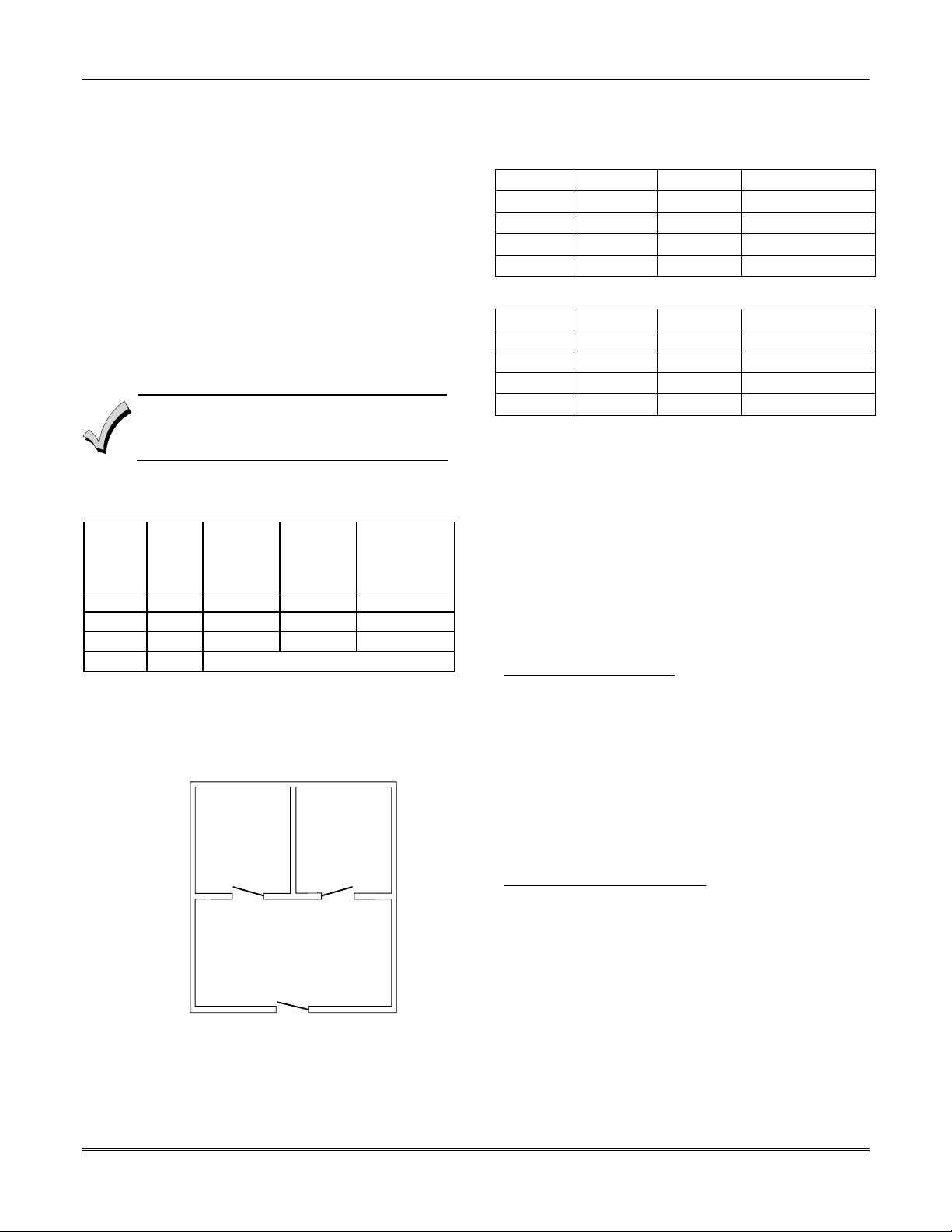
Example
Here is an example of how the lobby would react in a
typical setup.
OFFICE 1 OFFICE 2
COMMON LOBBY
MAIN ENTRANCE
V128BP-001-V0
User #1 has access to Office #1 and the Common Lobby.
User #2 has access to Office #2 and the Common Lobby.
Office #1 is set up to affect the Common Lobby, but not
arm it.
Office #2 is set up to affect and arm the Common Lobby.
NOTE: In the tables below, the notations in
parentheses ( ) indicate the current status of the other
partition when the user takes action.
Sequence #1:
Office 1 Office 2 Lobby Action
User #1:
User #2:
User #1:
User #2:
Disarms (Armed) Disarms
(Disarmed) Disarms No Change
Arms (Disarmed) No change
(Armed) Arms Arms
Sequence #2:
User #2:
User #1:
User #2:
User #1:
Office 1 Office 2 Lobby Action
(Armed) Disarms Disarms
Disarms (Disarmed) (No change)
(Disarmed) Arms No Change
Arms (Armed) No Change
Notice that in sequence #1, because Office #2 was the
last to arm, the lobby also armed (Office #2 is
programmed to affect and arm the lobby). In sequence
#2, the lobby could not arm when Office #2 armed,
because Office #1, which affects the lobby, was still
disarmed.
When Office #1 armed, the lobby still did not arm
because Office #1 was not programmed to arm the
lobby. User #1 would have to arm the lobby manually.
Therefore, you would want to program a partition to
affect and arm the lobby if the users of that partition
are expected to be the last to leave the building.
How User Access Codes Affect the Common Lobby
Codes with Global Arming
If a code is given "global arming" when it is defined (see
SECTION 9: User Access Codes), the keypad prompts
the user to select the partitions they want to arm. Only
the partitions the user has access to are displayed. This
allows the user to choose the partitions to be armed or
disarmed, and so eliminates the "automatic" operation
of the lobby. Keep in mind, however, that if a user
attempts to arm all, and another "affecting" partition is
disarmed, the user cannot arm the lobby, and the
message "UNABLE TO ARM LOBBY PARTITION" is
displayed.
Codes with Non-Global Arming
If a user arms with a non-global code, the lobby
partition operation is automatic, as described by fields
1*18 and 1*19.
Other Methods of Arming/Disarming
Common Lobby logic remains active when arming or
disarming a partition that affects and/or arms the
common lobby in one of the following manners:
• Quick-Arm
• Keyswitch
• Wireless Button
• Wireless Keypad
2-2

Section 2 – Partitioning and Panel Linking
Arming/Disarming Remotely
If a user arms or disarms remotely (through Compass
downloading software), the lobby does not automatically
follow another partition that is programmed to arm or
disarm the lobby. The lobby must be armed separately,
after arming all affecting partitions first.
Auto-Arming/Disarming
If scheduling is used to automatically arm and/or
disarm partitions, the common lobby partition does not
automatically follow another partition that is
programmed to arm or disarm the lobby.
Master Keypad Setup and Operation
Although this system has eight actual partitions, it
provides an extra partition strictly for the purpose of
assigning keypads as Master keypads for the system.
Assigning any keypad to Partition 9 in Device
Programming in the #93 Menu Mode makes that
keypad a Master keypad. A Master keypad reflects the
status of the entire system (Partitions 1-8) on its
display at one time. This is useful because it eliminates
the need for a building security officer to have to log on
to various partitions from one partition's keypad to find
out where an alarm has occurred.
The following is a typical display:
S Y S T E M 1 2 3 4 5 6 7 8
S T A T U S R R N N A ✴ B
Possible status indications include:
A = Armed Away S = Armed Stay M = Armed Maximum
C = Comm Fail I = Armed Instant R = Ready
N = Not Ready B = Bypassed/Ready
T = Trouble F = Fire Alarm P = AC Power Failure
L = Low System Battery
To obtain more information regarding a particular
partition, enter [✴] + Partition No. (e.g., [✴] + [4]). This
allows viewing only of that partition. In order to affect
that partition, the user must use a code that has access
to that partition.
Also, in order for a user of any partition to log on to
Partition 9 to view the status of all partitions, that user
must have access to all partitions. Otherwise, access is
denied.
The following is displayed for a fault condition on Zone
2 (Loading Dock Window) on Partition 1 (Warehouse)
when a user logs on from a keypad on Partition 9:
WHSE DISARMED
HIT ✴ FOR FAULTS
✴ = Alarm
The lobby must be included as a partition to be
armed/disarmed and must be scheduled as the last
partition armed.
If you are using auto-arming, make sure that
the Auto-Arm Delay and Auto-Arm Warning
periods, for the lobby partition, (fields 2*05 and
2*06) combined are longer than that of any
other partition that affects the lobby. This
causes the lobby to arm last.
Pressing [✴] causes the following display to appear at
Partition 1's keypad(s):
FAULT 002 LOADING
DOCK WINDOW
Additional zone faults are displayed one at a time. To
display a new partition's status, press [✴] + Partition
No.
The Armed LED on a Master keypad is lit only if all
partitions have been armed successfully. The Ready
LED is lit only if all partitions are "ready to arm."
Neither LED is lit if only some partitions are armed
and/or only some partitions are ready.
Press [✴] + [0] or [✴] + [9] to return to the master
partition. Otherwise, if no keys are pressed for 2
minutes, the system automatically returns to the
master partition
The sounder on a Master keypad reflects the sound of
the most critical condition on all of the partitions. The
priority of the sounds, from most to least critical, is as
follows:
1. Pulsing fire alarm sounds
2. Steady burglar alarm sounds
3. Trouble sounds (rapid beeping)
Silence the sounder by pressing any key on the Master
keypad or a keypad on the partition where the condition
exists.
A Master keypad uses the same panics as
Partition 1. Master keypad panics are sent to
Partition 1, and will activate on Partition 1.
Therefore, panics must be programmed for
Partition 1.
Panel Linking
Up to eight VISTA-128BPEN control panels may be
networked, enabling a user to control the features of all
control panels from a single location. The panel linking
bus supports an end-to-end network length of up to
4,000 feet. This makes it ideal for multi-building
environments (e.g., shopping mall, college campus, etc.).
U
Panel Linking is not permitted in UL
L
installations.
Panel linking requires a VA8200 Panel Link Module
(PLM) on each VISTA-128BPEN. Users can link (access
2-3

Vista-128BPEN Installation and Setup Guide
other control panels) in any of three different modes:
Single-Partition, Single-Panel Mode; Multi-Partition,
Multi-Panel Mode; Multi-Panel View Mode. These
modes are described later in this section.
Each PLM connects to the ECP bus on the control panel
and communicates to each PLM via an RS-485 bus (3wire twisted cable run) with a maximum wire-run of
4000 feet end-to-end.
• Users 001-050 are the only users that can
perform panel linking and are automatically
assigned panel linking access when added
to the system.
• An alpha keypad must be used for panel
linking.
• The system may take up to 7 seconds to
respond to a command when in a panel
linking mode
NOTE: A user cannot access partitions or panels that
they have not been assigned to.
Panel Link Module Supervision
The Panel Link Module can be supervised for its
connection to the control panel. The module’s
supervisory zone is zone 8xx, where “xx” = the ECP
address of the PLM. You must program that zone with
response type 05 (Day/Night) in Zone Programming in
the #93 Menu Mode (refer to the Programming Guide
for detailed programming instructions). If you want to
report the supervisory failure to the central station
and/or to a paging service, the appropriate reporting
parameters for that zone must be programmed.
If you want the supervisory failure of PLM(s) on other
linked control panels to display on this control panel,
they must be programmed into Zone Programming in
the #93 Menu Mode with response type 12 in this
control panel (refer to the Programming Guide for
detailed programming instructions). The panel ID
number for each module must match the panel ID
number programmed in Device Programming of its
“host” VISTA-128BPEN.
How to Use Panel Linking
Panel Linking can be used in any of three different
modes:
• Single-Partition, Single-Panel − displays status of a
partition on a remote control panel and allows
control of that remote control panel.
• Multi-Partition, Multi-Panel Mode − displays
status and allows arming/disarming of multiple
partitions at once on a remote control panel.
• Multi-Panel View Mode − displays status and
allows arming/disarming of multiple remote control
panels at a time.
NOTE: A user will not be able to access or view
partitions or panels that they have not been assigned
to.
2-4
Section 2 – Partitioning and Panel Linking
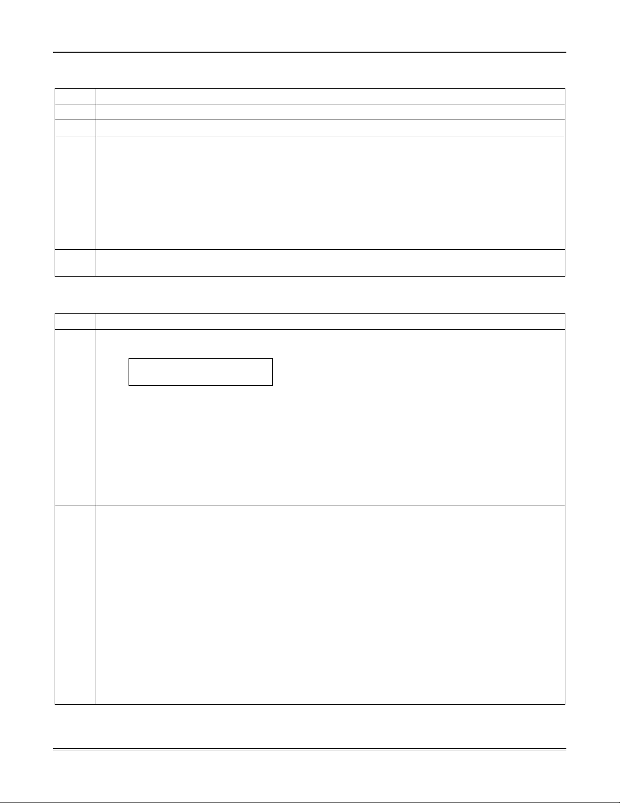
Single-Partition Single-Panel Mode
To access the Single-Partition, Single Panel mode, perform the following steps:
Step Action
1
2
3 Enter the partition number of the panel. The keypad displays “AWAITING PANEL LINK.” After a few
4
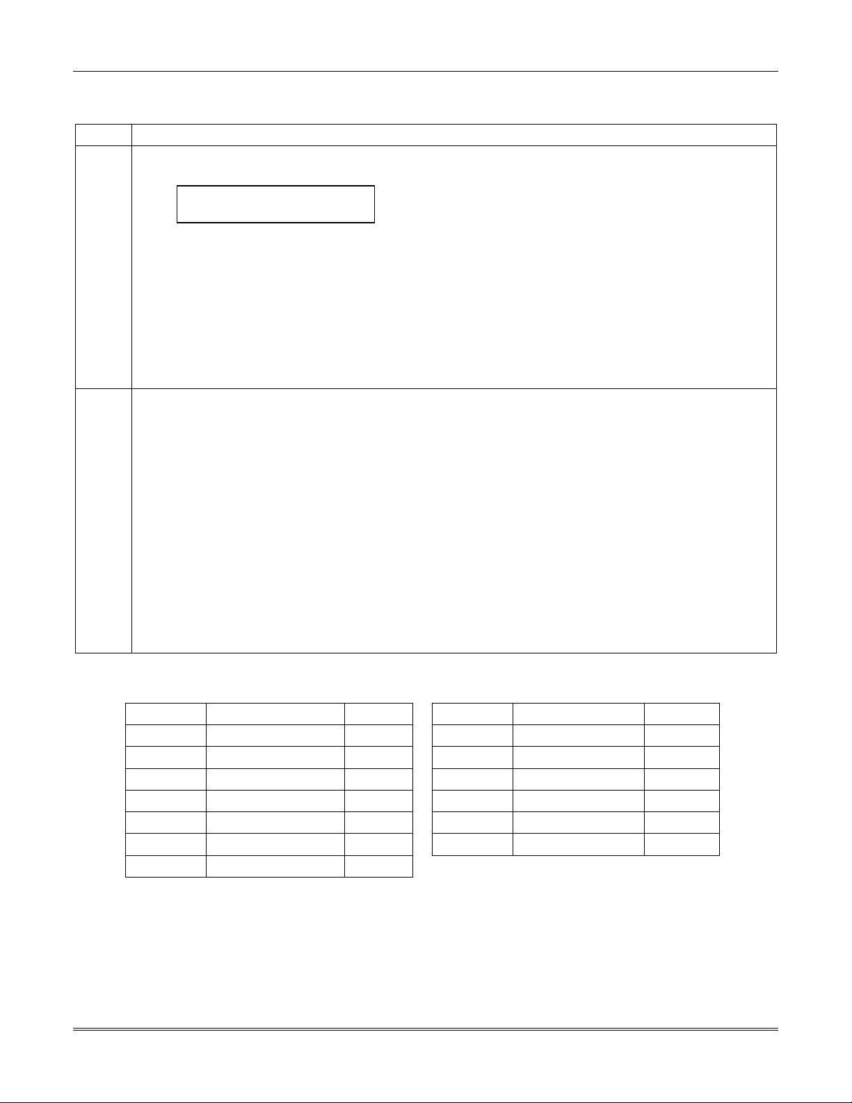
Multi-Partition Multi-Panel Mode
To perform a function in the Multi-Partition, Multi Panel mode, follow the steps below:
Step Action
1
2 The following functions can be performed:
Enter User Code (for users 001-050) + [#] + [86].
Enter the panel ID number (01-08) of the panel you want to link to.
seconds, the keypad displays the status of the partition along with the panel ID number and partition
number flashing in the upper right-hand corner. The user now has full control of the remote control panel.
All functions can be performed except the following:
• Those limited by the user’s authority level.
• The user cannot enter Installer Program mode.
• The user cannot execute another panel linking mode.
NOTE: To execute another panel linking mode or to access a different remote panel, the user must first exit
this mode (return to the original control panel).
To exit, enter the User Code (for users 001-050) + [#] + [85]. After a few seconds, the keypad displays the
status of the original partition for the keypad.
Enter User Code (for users 001-050) + [#] + [88].
The keypad displays the following:
PANELnn 1 2 3 4 5 6 7 8
STATUS x x x x x x x x
where “nn” = panel ID number (01-08), “12345678” are the partition numbers and “xxxxxxxx” is the status of
each partition of that panel. Status indications include:
A = Armed Away S = Armed Stay M = Armed Maximum
I = Armed Instant R = Ready N = Not Ready
B = Bypassed/Ready ✴ = Alarm T = Trouble
F = Fire Alarm P = AC Power Failure L = Low System Battery
C = Comm Fail
NOTES: See table later in this section for priority of displays.
A “•” under a partition number indicates the user does NOT have access to that partition.
Press [1] to attempt to disarm all partitions.
Press [2] to attempt to arm AWAY all partitions.
Press [3] to attempt to arm STAY all partitions.
Press [4] to attempt to arm MAXIMUM all partitions.
Press [7] to attempt to arm INSTANT all partitions.
Press [✴] to read the status of the next panel.
Press [#] key to read the status of the previous panel.
Press [0] to exit mode. After a few seconds, the keypad displays the status of the original partition of the
original panel for the keypad. Also, this mode will end in approximately 2 minutes if no keys are pressed.
NOTES: When performing any of the arming commands, if there are faults in any of the partitions, none
of the partitions will arm. These faults must be corrected or bypassed before attempting to arm.
When performing either a STAY or INSTANT arm command the system always arms in mode 1.
The user cannot execute another panel linking mode. To execute another panel linking mode or
to access a different remote panel, the user must first exit this mode (return to the original
control panel).
2-5
Vista-128BPEN Installation and Setup Guide
Multi-Panel View Mode
To perform a function in the Multi-Panel View mode, follow the steps below:
Step Action
1
2 The following functions can be performed::
Enter User Code (for users 001-050) + [#] + [87].
The keypad displays the following typical display:
ALLPANEL 1 2 3 4 5 6 7 8
STATUS x x x x x x x x
where “12345678” are the panel ID numbers and “xxxxxxxx” is the overall status of each panel. Status
indications include:
A = Armed Away S = Armed Stay M = Armed Maximum
I = Armed Instant R = Ready N = Not Ready
B = Bypassed/Ready ✴ = Alarm T = Trouble
F = Fire Alarm P = AC Power Failure L = Low System Battery
C = Comm Fail
NOTE: See table later in this section for priority of displays.
Press [1] to attempt to disarm all partitions on all panels.
Press [2] to attempt to arm AWAY all partitions on all panels.
Press [3] to attempt to arm STAY all partitions on all panels.
Press [4] to attempt to arm MAXIMUM all partitions.
Press [7] to attempt to arm INSTANT all partitions.
Press [0] to exit mode. After a few seconds, the keypad displays the status of the original partition of the
original panel for the keypad. Also, this mode will end in approximately 2 minutes if no keys are pressed.
NOTES:
When performing any of the arming commands, if there are faults in any of the partitions of a panel, the
system will not arm that panel, but will arm all the other partitions of the other panels.
When performing either a STAY or INSTANT arm command, the system always arms in mode 1 (see the
VISTA-128BPEN User Guide for a detailed explanation of the STAY and INSTANT arming modes).
The user cannot execute another panel linking mode. In order to perform another panel linking mode or to
access a different remote panel, the user must first exit this mode (return to the original control panel).
Priority of Displays for Multi-Partition and Multi-Panel Modes
This table shows the priority of displays if more than one of these conditions exists at the same time.
Priority Description Display Priority Description Display
1 Fire Alarm
2 All Other Alarms
3 AC Loss
4 Comm Fail
5 System Low Battery
6 Trouble
7 Bypass
F
✴
P
C
L
T
B
8 Not Ready
9 Ready
10 Armed STAY
11 Armed AWAY
12 Armed INSTANT
13 Armed MAXIMUM
2-6
N
R
S
A
I
M
SECTION 3
Installing the Control
•••••••••••••••••••••••••••••••••••••••••••••••••
This section describes the procedures for mounting and wiring the control panel and all the peripheral devices.
Mounting the Control Cabinet
To mount the control cabinet, perform the following steps:
Step Action
1 Before mounting the circuit board, remove the metal knockouts for the wiring entry that you will be using.
DO NOT ATTEMPT TO REMOVE THE KNOCKOUTS AFTER THE CIRCUIT BOARD HAS BEEN
INSTALLED.
2 Using fasteners or anchors (not supplied), mount the control cabinet to a sturdy wall in a clean, dry area
that is not readily accessible to the general public. The back of the cabinet has 4 holes for this purpose.
U
To provide certificated burglary service for UL installations, refer to the special requirements and
Cabinet Attack Resistance Considerations
L
ATTACK RESISTANCE, use the cabinet included in the VISTA-ULKT kit.
to follow. For UL Commercial Burglary installations that require
Figure 3-2
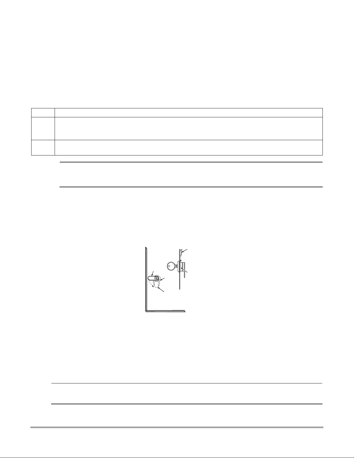
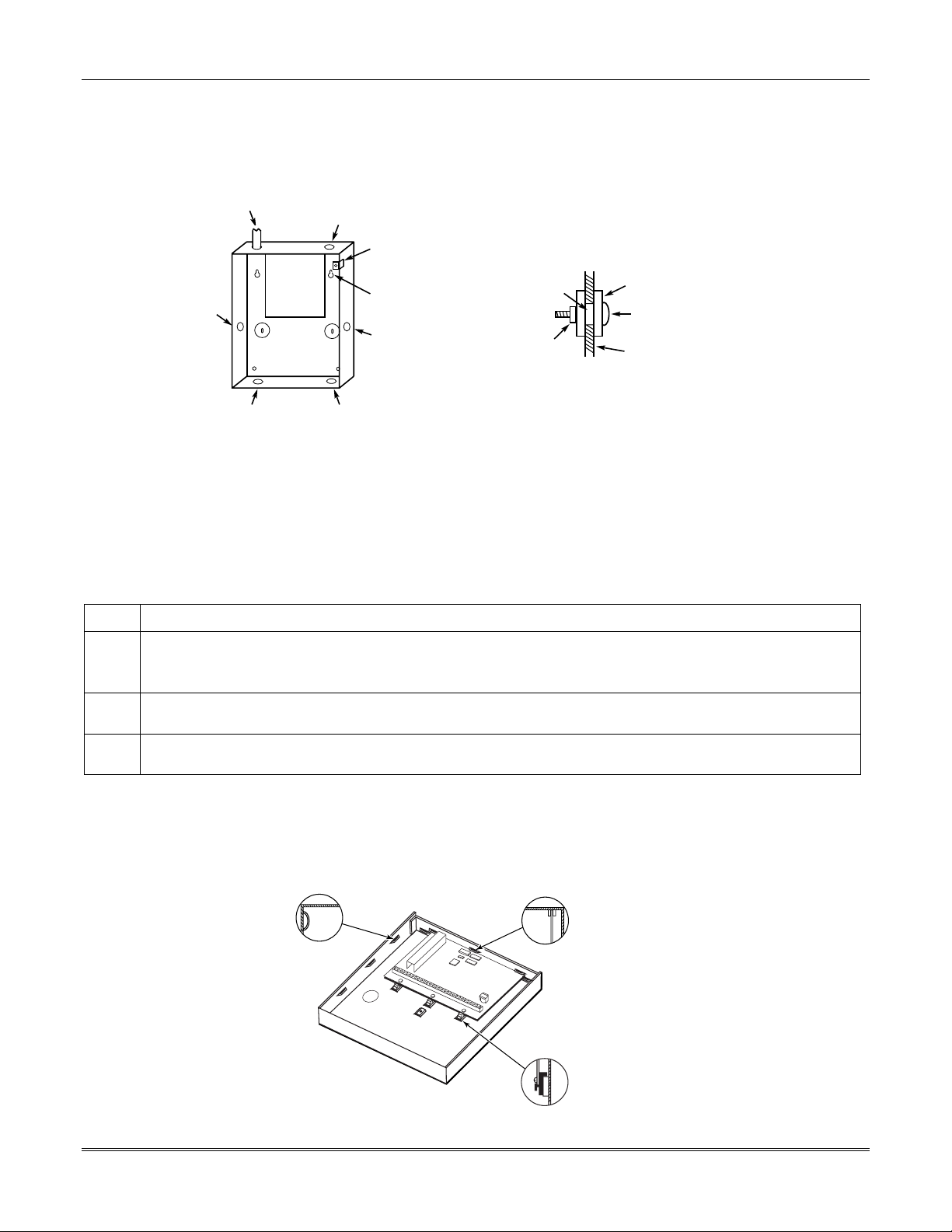
Installing the Cabinet Lock
1. Remove cabinet door, then remove the lock knockout from the door. Insert the key into the lock.
2. Position the lock in the hole (Figure 3-1), making certain that the latch will make contact with the latch bracket
when the door is closed.
3.
When correctly positioned, insert supplied lock clip on the inside of the cabinet into the slots on the
lock cylinder. Use ADEMCO Lock # N6277V1 and Lock Clip # P3422-2 (supplied).
LOCKED
RETAINER
CLIP
UNLOCKED
CABINET DOOR BOTTOM
Figure 3-1: Installing the Lock
RETAINER CLIP
(NOTE POSITION)
RETAINER
SLOTS
cab_lock_clip-001-V0
Mercantile Premises Listing Guidelines
• The panel door must be supervised. Mount the clip-on tamper switch (supplied) to the cabinet's right side wall as
shown in the diagram below, and wire it to one of the hardwire zones.
• Use a bell with a tamper-protected housing such as the ADEMCO AB12M. The bell housing's tamper switch and
inner tamper linings must also be wired to the hardwire zone.
• Assign the tampers’ hardwire zone to a burglary partition. Program the hardwire zone for day trouble/night alarm
(zone type 5) when only one burglary partition is used. Program it for 24-hr. audible alarm (zone type 7) when more
than one burglary partition is used.
24-Hour audible alarm (zone types 6 and 7) is not approved for ULC applications.
ULC
• All wiring between the bell and panel must be run in conduit. Remaining wires do not need to be run in conduit.
• All wiring that is not run in conduit must exit from the knockout openings on the bottom or back of the cabinet.
3-1
Vista-128BPEN Installation and Setup Guide
• All unused knockouts must be plugged using the disc plugs and carriage bolts (supplied), as indicated in the
diagram below.
• Fasten the cabinet door to the cabinet backbox using the 18 one-inch-long Phillips-head screws (supplied) after all
wiring, programming, and checkout procedures have been completed.
(Shows typical local Grade A listing installation)
RUN BELL WIRES
PLUG THIS
KNOCKOUT
IN CONDUIT
PC
BOARD
PLUG THIS
KNOCKOUT
CLIP-ON DOOR
TAMPER SWITCH
CABINET
MOUNTING
HOLE
(4 PLACES)
PLUG THIS
KNOCKOUT
TO PLUG AN UNUSED KNOCKOUT OPENING,
REMOVE KNOCKOUT AND INSTALL A PAIR OF
DISC PLUGS AND A CARRIAGE BOLT AS SHOWN.
DISC PLUGS (DIMPLES IN DISC
KNOCKOUT
OPENING
HEX NUT AND
WASHER
PLUG SHOULD REGISTER INSIDE
KNOCKOUT OPENING)
CARRIAGE BOLT
CABINET SIDE WALL
(OUTSIDE)
PLUG THIS
KNOCKOUT
RUN ALL REMAINING
WIRE THROUGH HERE
cabattack-001-V0
Figure 3-2: Cabinet Attack Resistance Considerations
• Mercantile Safe and Vault Listing GuidelinesFollow the guidelines given above for Mercantile Premises listing.
• Mount a shock sensor such as Sentrol No. 5402 to the control's backbox. Follow the manufacturer's instructions for
proper sensor mounting. This sensor also must be wired to a hardwire zone.
• For safe and vault applications, a UL Listed contact must be used inside the cabinet through one of the knockouts
for pry-off tamper purposes. This sensor also must be wired to a hardwire zone.
Installing the Control's Circuit Board
To install the circuit board in the cabinet, perform the following steps:
Step Action
1
2
3
NOTES:
• Make certain that the mounting screws are tight. This ensures that there is a good ground connection between the
• Dress field wiring away from the microprocessor (center) section of the PC board. Use the loops on the left and right
Hang the three mounting clips on the raised cabinet tabs. Refer to Figure 3-3 (Detail B).
Make sure the clip orientation is exactly as shown in the diagram to avoid damage. This will also avoid
problems with insertion and removal of the PC board.
Insert the top of the circuit board into the slots at the top of the cabinet. Make certain that the board rests in
the slots as indicated (Detail A).
Swing the base of the board into the mounting clips and secure the board to the cabinet with the
accompanying screws.
PC board and the cabinet.
sidewalls of the cabinet for anchoring field wiring using tie wraps (Detail C). These steps are important to minimize
the risk of panel RF interference with television reception.
DETAIL A
SIDE VIEW OF
BOARD INSERTED
INTO SLOTS
DETAIL C
SIDE VIEW
OF SLOTS
+
+
+
3-2
DETAIL B
SIDE VIEW OF SHORT
MOUNTING CLIPS
(TYP.)
Figure 3-3: Mounting the PC Board
hi_end_mnt-PCB
Installing the Control
g
Installing the Keypads
Up to 31 addressable keypads (addresses 00-30) may be used (you may need to use an auxiliary power supply if the
750mA aux. output is exceeded).
NOTE: Refer to the Alpha Vocabulary list found in the #93 Menu Mode in the Programming Guide for list of the words
annunciated by the 6160V.
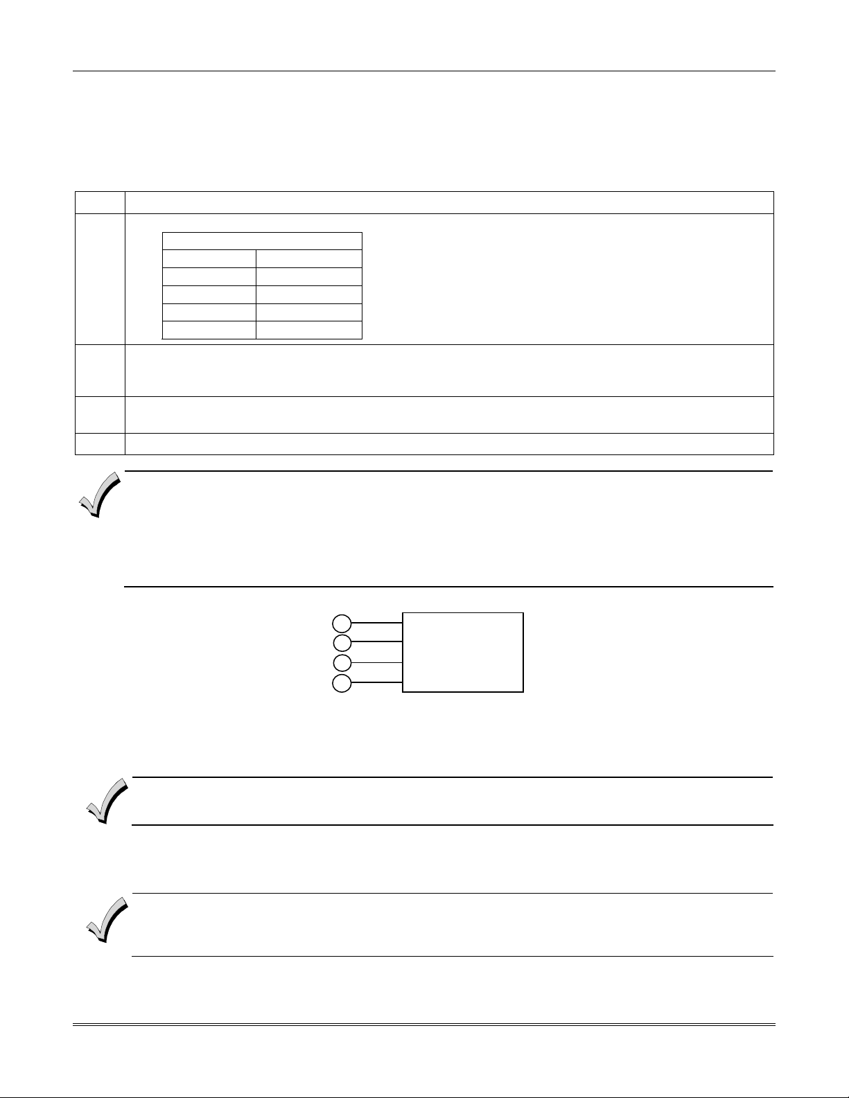
To wire the keypads, perform the following steps:
Step Action
1
2 Wire keypads to a single wire run or connect individual keypads to separate wire runs. The maximum wire
3 Run field wiring from the control to the keypads (using standard 4-conductor cable of the wire gauge
4 Connect the keypad(s) to terminals 6, 7, 8, and 9 on the control board, as shown in Figure 3-4.
Determine wire gauge by referring to the Wire Run Length/Gauge table below.
Wire Run Length/Gauge Table
Wire Gauge Length
#22 gauge 450 feet
#20 gauge 700 feet
#18 gauge 1100 feet
#16 gauge 1750 feet
run length from the control to a keypad, which is homerun back to the control must not exceed the lengths
listed in the table.
determined in step 1).
• The length of all wire runs combined, regardless of the wire gauge, must not exceed 2000 feet when unshielded
quad conductor cable is used (1000 feet if unshielded cable is run in conduit, which acts a shield, or if shielded
cable is used).
• If more than one keypad is wired to one run, then the above maximum lengths must be divided by the number of
keypads on the run (e.g., the maximum length is 225 feet if two keypads are wired on a #22 gauge run).
RED
6
BLACK
7
GREEN
8
YELLOW
9
CONTROL
TERMINALS
KEYPADS
Figure 3-4: Keypad Connections to Control Panel
Addressing the Keypads
Set each keypad for an individual address (00-30) according to the keypad's instructions. Set an alpha keypad for
address 00 and other keypads for higher addresses (00 and 01 are enabled in the system's default program). Any
keypads set for address 02 and above will appear blank until they are enabled in the system's program. Each keypad
must be set for a different address.
• Do not set any keypads to address 31 (nonaddressable mode). They will interfere with other keypads (as well as
• If an “OC” or “OPEN CIRCUIT” message is present on a keypad, data from the control is not reaching the
The keypads will not operate until they are physically addressed and enabled in the system's
in the
#93 Menu Mode
.
other devices) connected to the keypad terminals.
keypad. Check your wiring.
Device Programmin
3-3
Vista-128BPEN Installation and Setup Guide
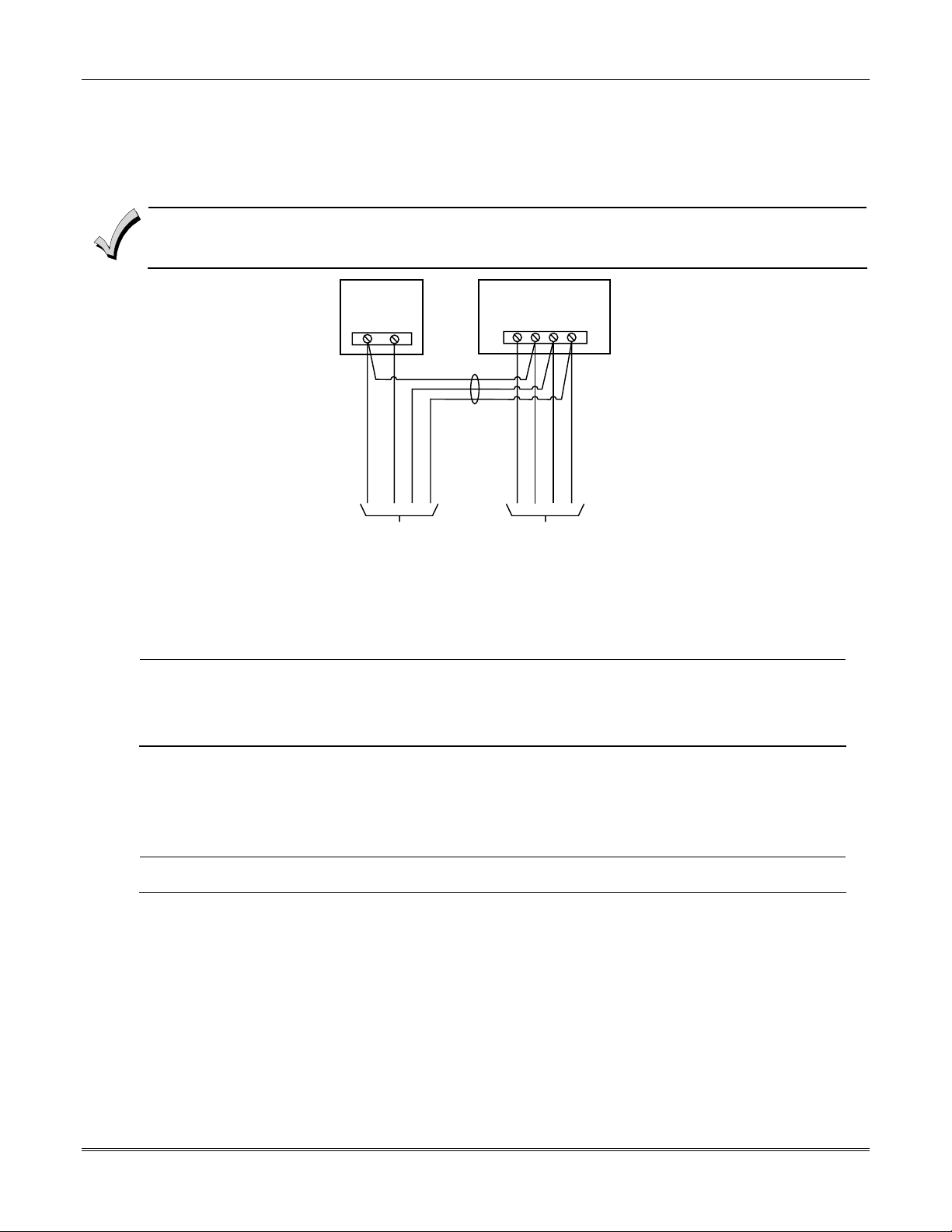
Supplementary Power Supply for Additional Keypads
When the control’s auxiliary power load for all devices exceeds 750mA, you can power additional keypads from a
regulated 12VDC power supply (e.g., ADEMCO AD12612 (1.2A)). Use a UL Listed, battery-backed supply for UL
installations.
Connect the additional keypads as shown in Figure 3-5, using the keypad wire colors shown. Be sure to observe the
current ratings for the power supply used.
• Make connections directly to the screw terminals as shown in
• Be sure to connect the negative (–) terminal on the power supply unit to terminal 7 (–) on the control.
present).
SUPPLEMENTARY
POWER SUPPLY
+
–
RED WIRE
BLACK WIRE
CONNECTIONS
TERMINALS AS
YELLOW WIRE
GREEN WIRE
CONTROL TERMINAL STRIP
IMPORTANT:
MAKE THESE
DIRECTLY TO
SCREW
SHOWN.
Figure 3-5
AUX. DATA
AUX.
IN
+
–
678 9
BLACK WIRE
RED WIRE
GREEN WIRE
DATA
OUT
YELLOW WIRE
. Make no connection to the blue wire (if
TO
SECONDARY
KEYPAD
TO
MAIN
KEYPAD
pwr_supply-002-V0
Figure 3-5: Using A Supplementary Power Supply
Installing External Sounders
The VISTA-128BPEN provides a bell circuit output for operating fire and burglary alarm notification appliances. The
alarm output is rated as follows: 10VDC – 14VDC, 1.7A max., power-limited.
• For Household Fire and combination Household Fire/Burglary installations, the total current drawn from the
U
L
auxiliary power, polling loop, and alarm output combined must not exceed 750mA.
• For Household Burglary installations, the total current drawn from the alarm output must not exceed 1.7A. A
battery must be installed, as it supplies the current for the combined auxiliary power, polling loop, and alarm
output in excess of 750mA.
The output has the following options:
• Selectable for supervision.
• Selectable for confirmation of arming ding.
• Selectable to chime when entry/exit or perimeter zones are faulted.
• Selectable for timeout of 2-30 minutes.
UL
Burglary bell circuits must be programmed for a timeout of 16 minutes or longer.
UL985 Household Fire or Combination Household Fire/Burglary Installations
For installations that must provide UL Listed protection, the total combined current drawn from the alarm output,
auxiliary power output, and polling loop must not exceed 750mA in order to comply with the battery independence
requirements. If, for example, two System Sensor MH piezo alarm sounders, wired in parallel, are used (24mA total),
then 726mA (750mA – 24mA) is available for auxiliary output and polling loop use.
UL1023 Household Burglary Installations
For Household Burglary installations, the total current drawn from the alarm output must not exceed 1.7A. A battery
must be installed, as the battery supplies current from the combined auxiliary power, polling loop, and alarm output in
excess of 750mA.
Non-UL Installations
For non-UL installations, the total current drawn from this output can be up to 1.7A. A battery must be installed, as the
battery supplies current in excess of 750mA. Up to two 719 sirens can be used wired in parallel.
3-4
Installing the Control
U
This control complies with National Fire Protection Association (NFPA) requirements for temporal pulse sounding
L
of fire notification appliances.
Alarm Output Supervision
When supervision is enabled, the VISTA-128BPEN monitors the alarm output wiring for open and short circuit faults
while the output is inactive. The system provides a trouble indication (Zone 970) when an open occurs; or when a short
occurs between the Bell (+) and Bell (-) terminal wiring, or between the Bell (+) terminal wiring and earth ground.
U
NOTE: When supervising the bell output (zone 970), only one device can be connected to the alarm output
L
(terminals 4 and 5) for UL and Fire installations.
The VISTA-128BPEN indicates the trouble condition regardless of whether the system is armed or disarmed. The zone
displays on the keypads, reports to the event log, and transmits to the central station (if programmed) on Partition 1.
The Contact ID event code is 321, Bell Trouble. The trouble is cleared from the display by entering the user code + OFF.
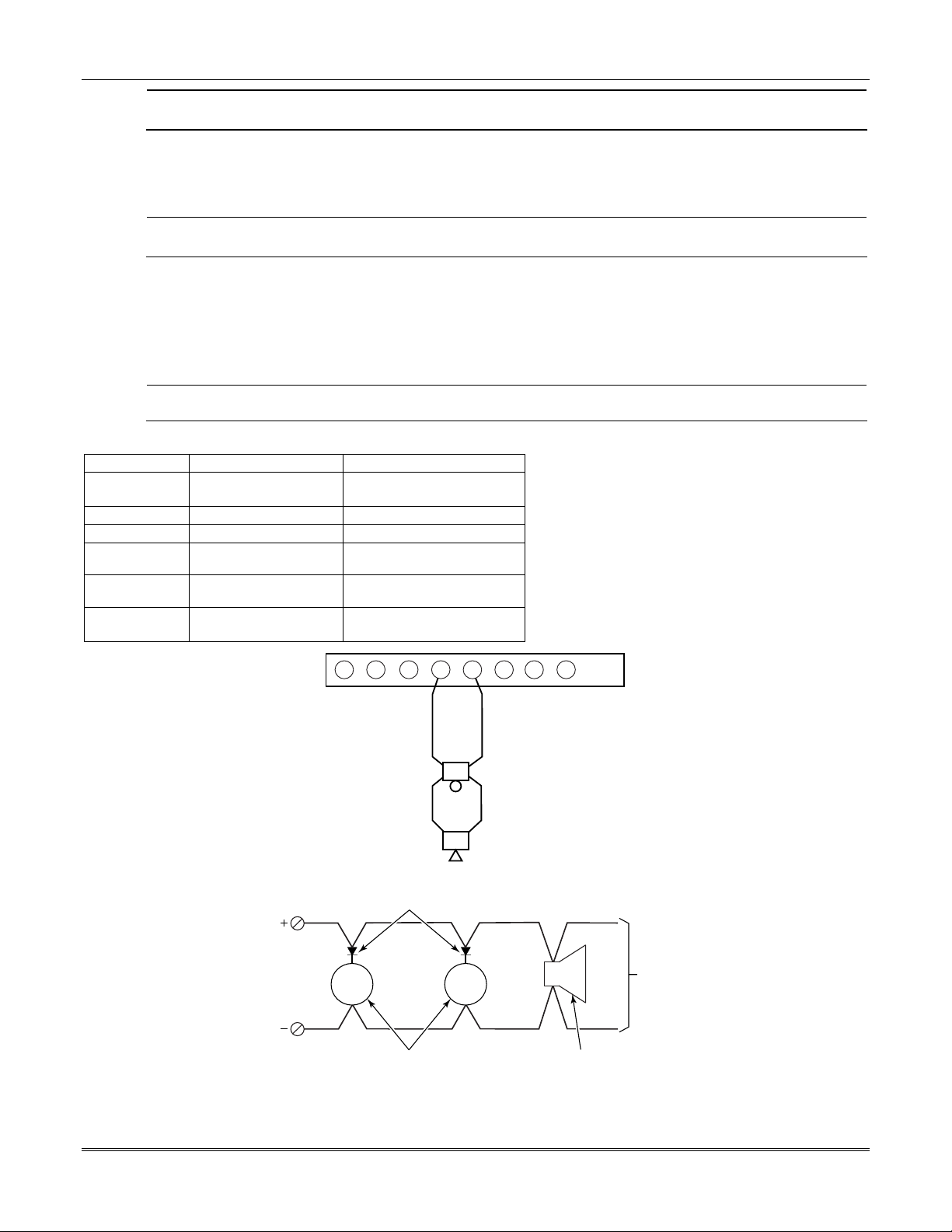
Wiring the Alarm Output
The wiring of the alarm output depends upon whether you are going to supervise the output or not. Use the appropriate
procedure below for your application.
U
Use only UL Listed sounding devices for UL installations.
L
Compatible Alarm Indicating Devices
Model Number Device Type Polarizing Diode
719 Compact Outdoor Siren
(not UL Listed)
747 Indoor Siren Yes
AB12M Bell Yes
System Sensor
Fire Piezo Horn No
HR
System Sensor
Fire Horn/Strobe No
P2RK, P4RK
Wheelock
AS-121575W
Fire Horn/Strobe No
Yes
3
2
1
ALARM SOUNDER OUTPUT:
1-VDC - 13.8VDC
1.7A MAXIMUM
4
5
+
-
7
6
8
+
-
BELL
HORN
fire_devices-001-V0
Figure 3-6: Wiring Polarized Fire Devices
POLARIZING DIODES
PANEL BELL
PANEL BELL
(MUST MOUNT AT INDICATING DEVICE)
BELL
NONPOLARIZED BURGLARY
INDICATING DEVICES
BELL
HORN
POLARIZED FIRE
INDICATING DEVICE
TO
OTHER
DEVICES
non_polar_devices
Figure 3-7: Wiring Nonpolarized Burglary Devices
3-5

Vista-128BPEN Installation and Setup Guide
Supervising the Alarm Output
To wire the alarm output using the supervision feature, perform the following steps:
Step Action
1 Wire polarized fire-indicating devices to the alarm output as shown in Figure 3-6.
2 Wire nonpolarized burglary indicating devices to the alarm output using a polarizing diode (two 2A diodes
supplied), as shown in Figure 3-7.
3 Program Zone 970 with a response type of 05 (trouble by day/alarm by night).
NOTE: When supervising the bell output (zone 970), only one device can be connected to the alarm output
(terminals 4 and 5) for UL and Fire installations.
The minimum load on the alarm output must exceed 5mA at 12V for proper supervision operation.
U
Using a Siren Driver
To install a siren driver, perform the following steps:
Step Action
1 Mount the siren driver in the panel’s cabinet.
2 Wire the siren driver to the control and to the speaker(s). (See the driver’s instructions.)
3 Cut the blue jumper on the upper left-hand corner of the panel’s PC board.
4 Program Zone 970 with no response type (00).
If a device such as a siren driver with a high-resistance trigger input (drawing less than 5mA) is used in a UL
L
Household Fire installation, the siren driver must independently supervise siren speaker wiring.
Disabling the Supervision of the Alarm Output
To install the alarm output and disable the supervision feature, perform the following steps:
Step Action
1 Wire the devices to terminals 4 and 5, observing polarity if necessary.
2 Cut the blue jumper on the upper left-hand corner of the panel’s PC board.
3 Program Zone 970 with no response type (00).
Telephone Line Connections
Connect the main dialer output to telephone company lines using the RJ31X cables supplied.
U
The telephone line inputs have overvoltage protection in accordance with UL1459, as specified in UL985/UL1023.
L
The system is shipped defaulted for Contact ID format. It is the only format capable of uniquely reporting all 128
zones, as well as openings and closings for all 150 users. This requires central stations to be equipped with the
MX8000 receiver to fully support all new VISTA-128BPEN report codes. If you need to update your MX8000
receiver, contact your distributor.
To prevent the risk of shock, disconnect phone lines at the telco jack before servicing.
If the communicator is connected to a PABX, be sure it has a backup power supply that can support the PABX for
not
24 hours (central station) or 60 hours (remote station). Many PABXs are
in a communication failure if power is lost
.
power-backed up, and this can result
3-6
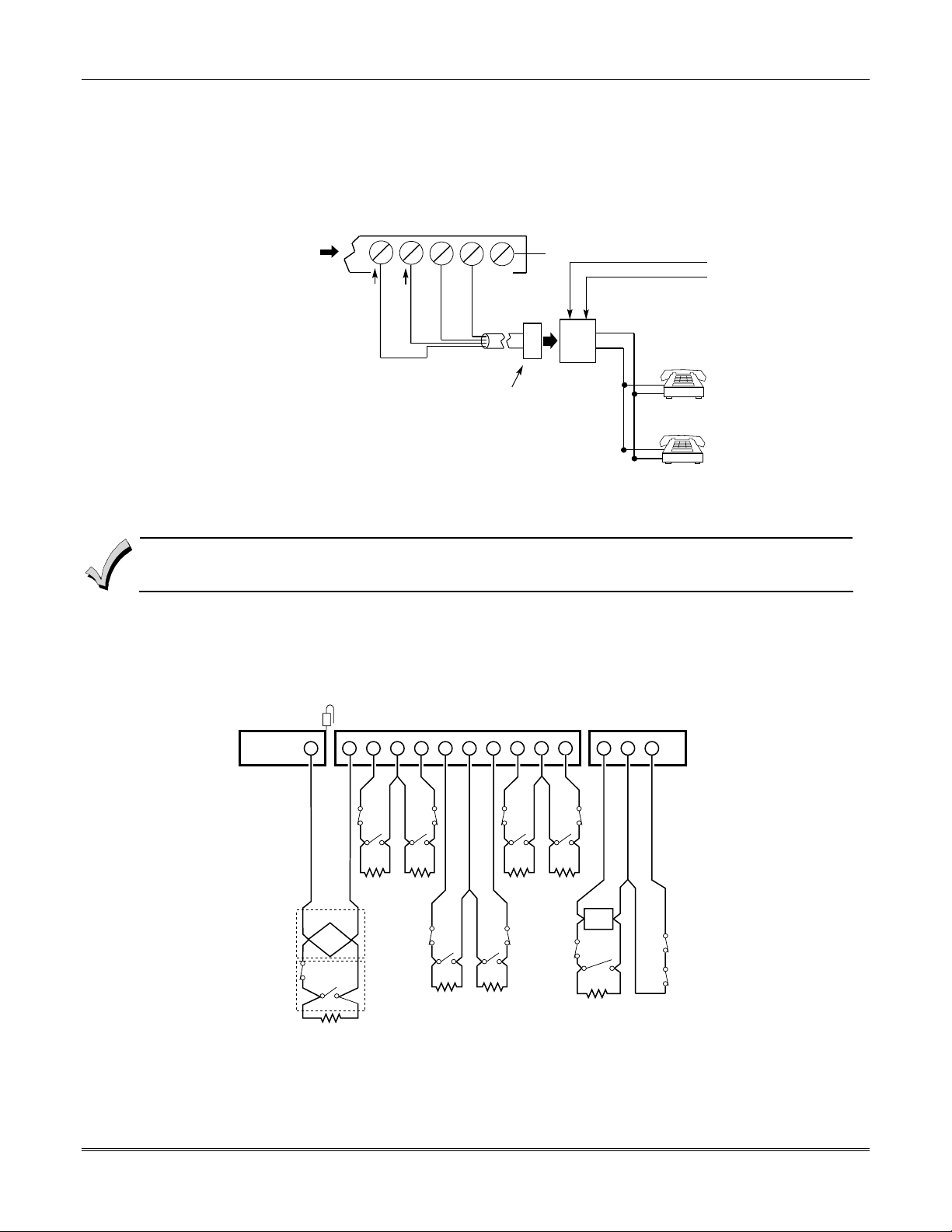
Installing the Control
Reporting Formats
The system supports the following formats:
ADEMCO Low Speed 3+1; 4+1; 4+2; Sescoa/Radionics 3+1; 4+1; 4+2; ADEMCO 4+2 Express; ADEMCO High Speed;
ADEMCO Contact ID
TERMINALS
ON CONTROL
Incoming
Handset
{
26 27 28 29 30
BROWN (TIP)
Telco Line
{
GREEN (TIP)
GREY (RING)
DIRECT
CONNECT
CORD
RED (RING)
GROUND
PLUG
EARTH GROUND
INCOMING TELCO LINE
TIP
RING
TIP
RJ31X
RING
JACK
PREMISES
PHONES
Figure 3-8: Telephone Line Connections
Wiring Burglary, Panic and Smoke Detector Devices to Zones 1-9
The maximum zone resistance is 100 ohms for zones 1 and 8, and 300 ohms for all other zones (excluding the
2K EOL resistor).
To wire burglary and panic devices to zones 1-9, connect sensors/contacts to the hardwire zone terminals (10 through
23). See Figure 3-9. Connect N.C. and N.O. devices as follows:
• Connect N.C. devices in series with the high (+) side of the loop. The 2K EOL resistor must be connected in series
with the devices, following the last device.
• Connect N.O. devices in parallel (across) the loop. The 2K EOL resistor must be connected across the loop wires
at the last device.
Red Jumper
10 11 12 13 14 15 16 17 18 19 20 21 22 23
ZONE 1
+-
SMOKE
N.C.
N.O.
2k EOLR
hw-zones-002-V0
ZONE 2 ZONE 3 ZONE 4 ZONE 5 ZONE 6 ZONE 7 ZONE 8 ZONE 9
++
-
N.C.
N.O.
2k EOLR 2k EOLR
2-WIRE SMOKE
DETECTOR LOOP
Usage
Usage
(Also supports NO/NC Burg contacts)
N.C.
N.O. N.O.
Fire
Burg.
Zone resistance (Excluding EOLR):
ZONE 1,8: 100 OHMS MAXIMUM
ALL OTHER ZONES: 300 OHMS MAXIMUM
++
N.C.
N.O. N.O.
2k EOLR 2k EOLR
++
N.C.
2k EOLR
-
N.C.
-
2k EOLR
N.C.
N.O.
BREAK DETECTORS
LATCHING TYPE GLASS
++-
GLASS
BREAK
N.C.
N.O.
2k EOLR
Zone response time:
ZONES 1-9: 350mSec-500mSec
N.C.
N.C.
Figure 3-9: Wiring Connections for Zones 1-9 Using 2-Wire Smoke Detectors on Zone 1
Zone 1 can support up to 16 2-wire smoke detectors.
3-7
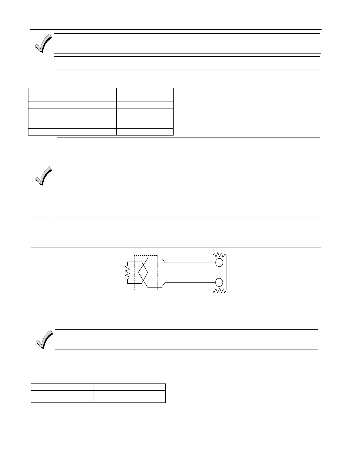
Vista-128BPEN Installation and Setup Guide
The alarm current on zone 1 supports only one smoke detector in the alarmed state.
U
U
In UL985 household fire installations, zone 1 is the only hardwired zone that may be used for fire. Polling
L
loop/wireless zones programmed as fire are not affected.
These smoke detectors are UL Listed for use with the VISTA-128BPEN and are the only 2-wire smoke detectors
L
that may be used.
Compatible 2-Wire Smoke Detectors
DETECTOR TYPE DEVICE MODEL #
Photoelectric, direct-wire System Sensor 2W-B
Photoelectric w/heat sensor, direct-wire System Sensor 2WT-B
Ionization w/B401B base System Sensor 1451
Photoelectric duct detect (DH400 base) System Sensor 2451
Ionization duct detector (DH400 base) System Sensor 1451DH
Ionization, direct-wire System Sensor 1100
Photoelectric w/B110LP base System Sensor 2151
Wiring 2-Wire Smoke Detectors to Zone 1
2K EOL resistors must be used on fire zones and must be connected across the loop wires of each zone at the
last detector.
To wire 2-wire smoke detectors to zone 1, perform the following steps:
Step Action
1 Select up to 16 2-wire smoke detectors from the list of compatible detectors.
2 Connect 2-wire smoke detectors across zone 1 terminals (10 and 11) as shown in Figure 3-10. Observe proper
polarity when connecting the detectors.
3
Connect the EOL resistor at the last detector in the loop across the zone 1 terminals. The EOL resistor
must be connected across the loop wires at the last detector.
2k EOLR
SMOKE
(+)
(-)
2-WIRE SMOKE
DETECTOR
ZONE 1
(+)
10
(-)
11
Figure 3-10: 2-Wire Smoke Detector on Zone 1
Using 4-Wire Smoke Detectors on Zones 1-8
You may use as many 4-wire smoke detectors as can be powered from the panel's Auxiliary Power output without
exceeding the output's rating (750mA).
• NFPA limits the number of 4-wire smoke detectors to 18 per zone.
• Auxiliary power to 4-wire smoke detectors is not automatically reset after an alarm, and therefore must be
momentarily interrupted using either the J7 smoke detector reset output trigger or a 4204 Relay Module.
Compatible 4-Wire Smoke Detectors
Use any UL Listed 4-wire smoke detector that is rated for 10-14VDC operation and that has alarm reset time not
exceeding 6 seconds. Some compatible 4-wire smoke detectors are listed below.
Detector Type Detector Model #
Photoelectric, direct wire System Sensor 4W-B
Photoelectric w/heat
sensor, direct wire
System Sensor 4WT-B
Wiring 4-Wire Smoke Detectors
3-8
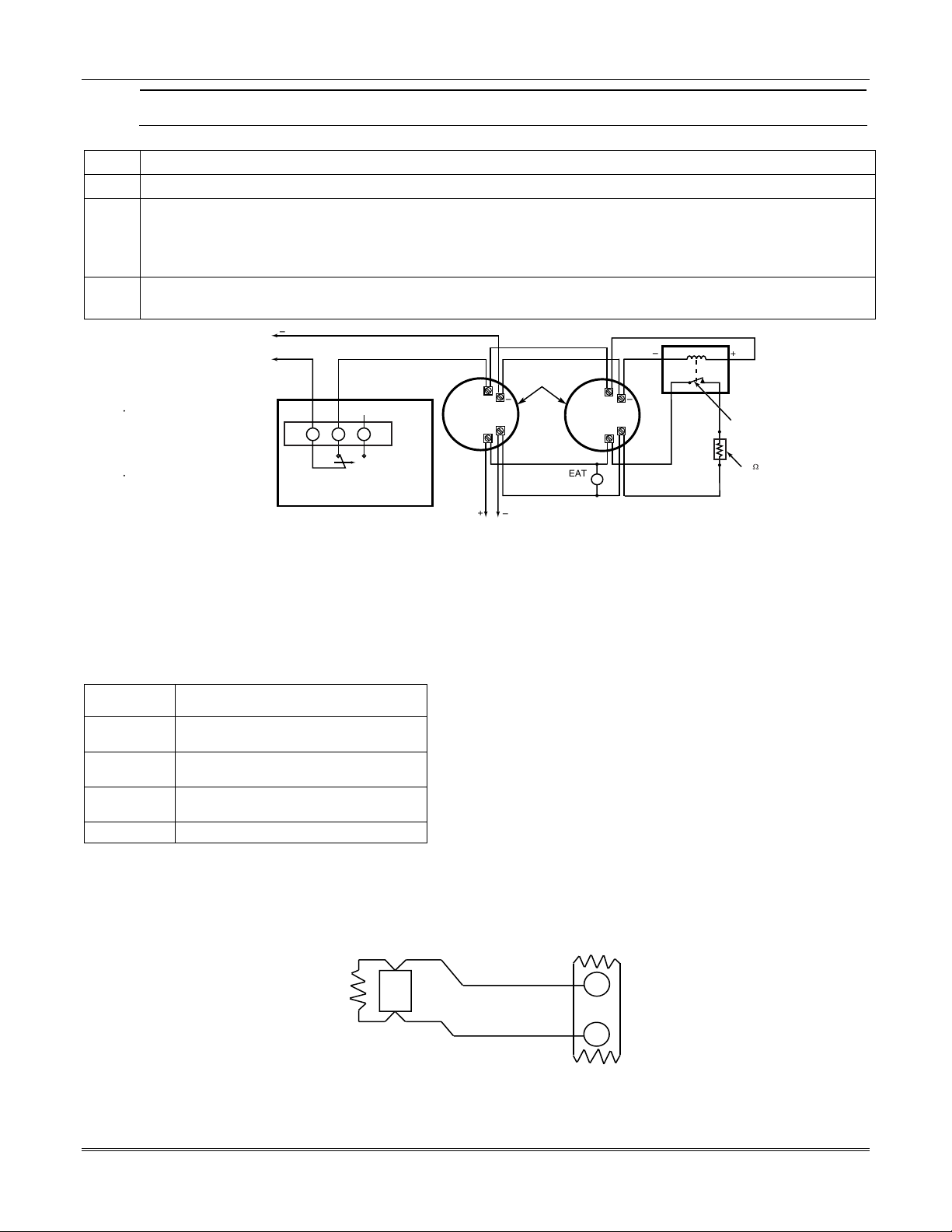
Installing the Control
U
Power to 4-wire smoke detectors must be supervised with an EOL device (use a System Sensor EOLR-1 EOL relay
L
module connected as shown in
Figure 3-11
).
To wire 4-wire smoke detectors to zones 1-8, perform the following steps:
Step Action
1 Select 4-wire smoke detectors (see list of compatible detectors shown previously).
2 Connect detectors (including heat detectors, if used) across terminals of the zone selected. All detectors must
be wired in parallel. See Figure 3-11.
NOTE: If you are using the J7 output trigger to reset the smoke detectors, refer to Smoke Detector Reset later
in this section for the wiring instructions.
3
Connect the EOLR at the last detector in the loop across the zone’s terminals. You must connect the EOLR
across the loop wires at the last detector.
AUXILIARY
POWER
TERMINALS
NOTES:
· PROGRAM THE RELAY TO
TRANSFER ON FIRE ZONE
RESET (ACTIVATION CODE 54).
SEE 4204 RELAY MODULE
SECTION FOR DETAILS.
· SECOND CODE AND OFF
ENTERED AT CONSOLE
MOMENTARILY INTERRUPTS
DETECTOR POWER.
+
NC
C
RELAY 1, 2, 3, OR 4
4204 RELAY MODULE
NO CONNECTION
NO
RESET
+
_
+
TO
FIRE ZONE
TERMINALS
4-WIRE
SMOKE
DETECTORS
_
DETECTOR
+
HEAT
_
_
+
EOL POWER
SUPERVISION
RELAY MODULE
A77-716B
SHOWN POWERED.
RELAY OPENS WHEN
POWER IS LOST.
2k
EOLR
V128BP-002-V0
_
TO
Figure 3-11: 4-Wire Smoke Detectors
Using 2-Wire Latching Glassbreaks on Zone 8
Zone 8 can support 2-wire glassbreak detectors. The zone provides enough standby current to power up to 50 2-wire
glassbreak detectors meeting the requirements listed below.
Compatible Glassbreak Detectors
Use detectors that meet the following ratings:
Standby
Voltage:
Standby
Resistance:
Alarm
Resistance:
Alarm
Current:
Reset Time:
5VDC–13.8VDC
Greater than 20k ohms (equivalent
resistance of all detectors in parallel)
Less than 1.1k ohms (see note below)
2mA–10mA
Less than 6 seconds
NOTES:
• You can use detectors that exceed 1.1k ohms in alarm, provided they maintain a voltage drop of less than 3.8 volts in
alarm.
• The ADEMCO ASC-SS1 detector has been tested and found to be compatible with these ratings.
GLASSBREAK
DETECTOR
2000
OHMS
EOLR
ZONE 8
LATCHING TYPE GLASS
BREAK DETECTOR LOOP
21
22
(+)
(-)
Figure 3-12: Wiring Latching Glassbreaks to Zone 8
3-9
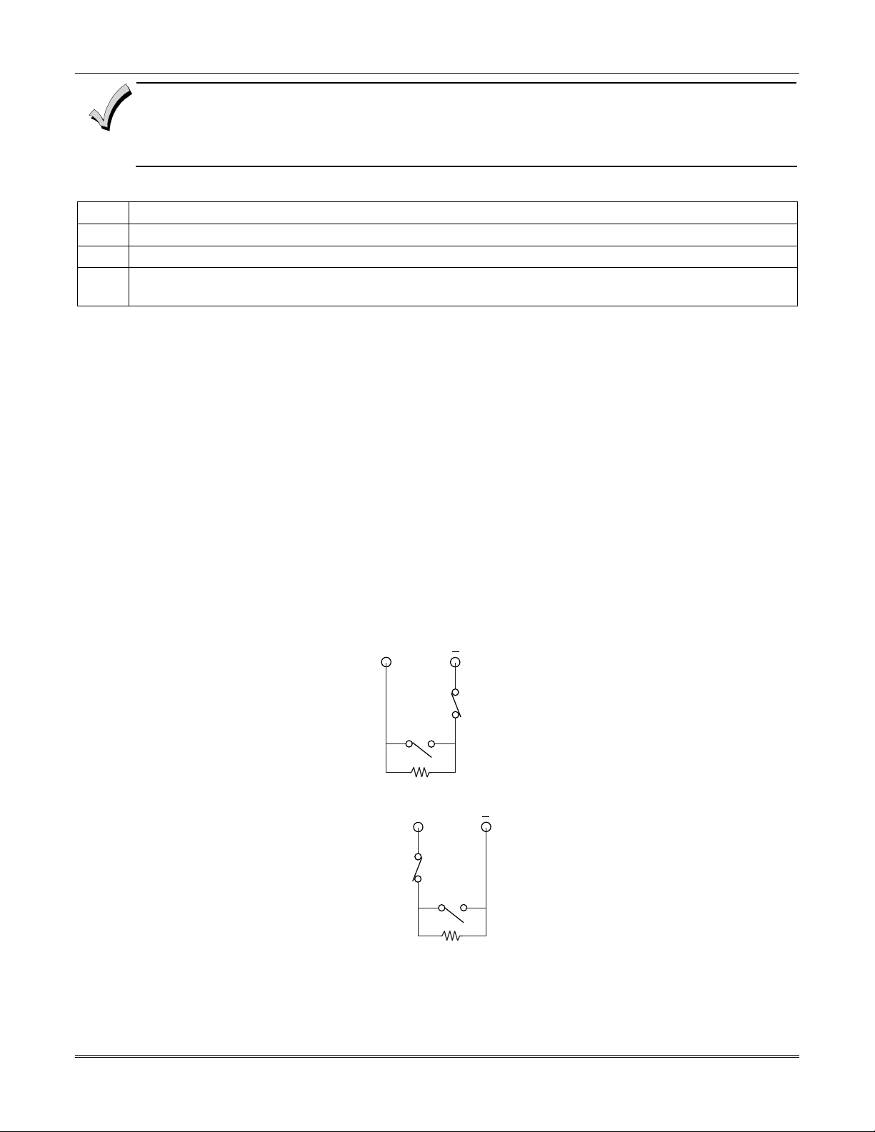
Vista-128BPEN Installation and Setup Guide
• The alarm current provided by zone 8 supports only one glassbreak detector in the alarmed state.
• Do not use other contacts when using glassbreak detectors on zone 8. Other contacts may prevent proper
glassbreak detector operation.
To wire 2-wire latching glassbreak detectors to zone 8, perform the following steps:
Step Action
1 Select 2-wire glassbreak detectors that meet the requirements stated previously.
2 Connect detectors across zone 8 (terminals 21 and 22). See Figure 3-12.
3
Tamper Supervision for the Hardwired Zones
The system can be programmed to monitor for either an open condition or a short condition of a tamper switch on zones
1-8. End-of-line supervision is required for this option.
Wiring a Tamper Switch to Zones 1-8
The wiring of the tamper switch depends on whether the tamper switch and the sensor are normally open or normally
closed.
• If you are using a normally closed sensor, the tamper switch must be normally open. Refer to Figure 3-13 for
• If you are using a normally open sensor, the tamper switch must be normally closed. Refer to Figure 3-13 for
• For the normally closed sensor, program the zone for trouble on short. For the normally open sensor,
To wire a tamper switch on a hardwired zone, connect the EOL resistor at the last detector in the loop across the zone’s
terminals. You must connect the EOL resistor at the last detector for proper operation of the tamper
supervision.
NOTE: These zones cannot be programmed for any 24 hour zone type and that tamper supervision is only in the
disarmed state. When armed goes into alarm.
NOTE: For zones with a response type of 9 or 16 (Fire), the tamper selection must be “0” none.
Connect the EOL resistor at the last detector in the loop across the zone’s terminals. You must connect the
EOL resistor across the loop wires at the last detector.
the wiring configuration.
the wiring configuration.
program the zone for trouble on open.
+
3-10
SENSOR
TAMPER
SWITCH
2k EOLR
Figure 3-13: Wiring a Normally Closed Loop for Tamper Supervision
+
TAMPER
SWITCH
SENSOR
2k EOLR
Figure 3-14: Wiring a Normally Open Loop for Tamper Supervision
 Loading...