

via30+, VISTA 10,411lXM
N7229 7194
ADEMCO
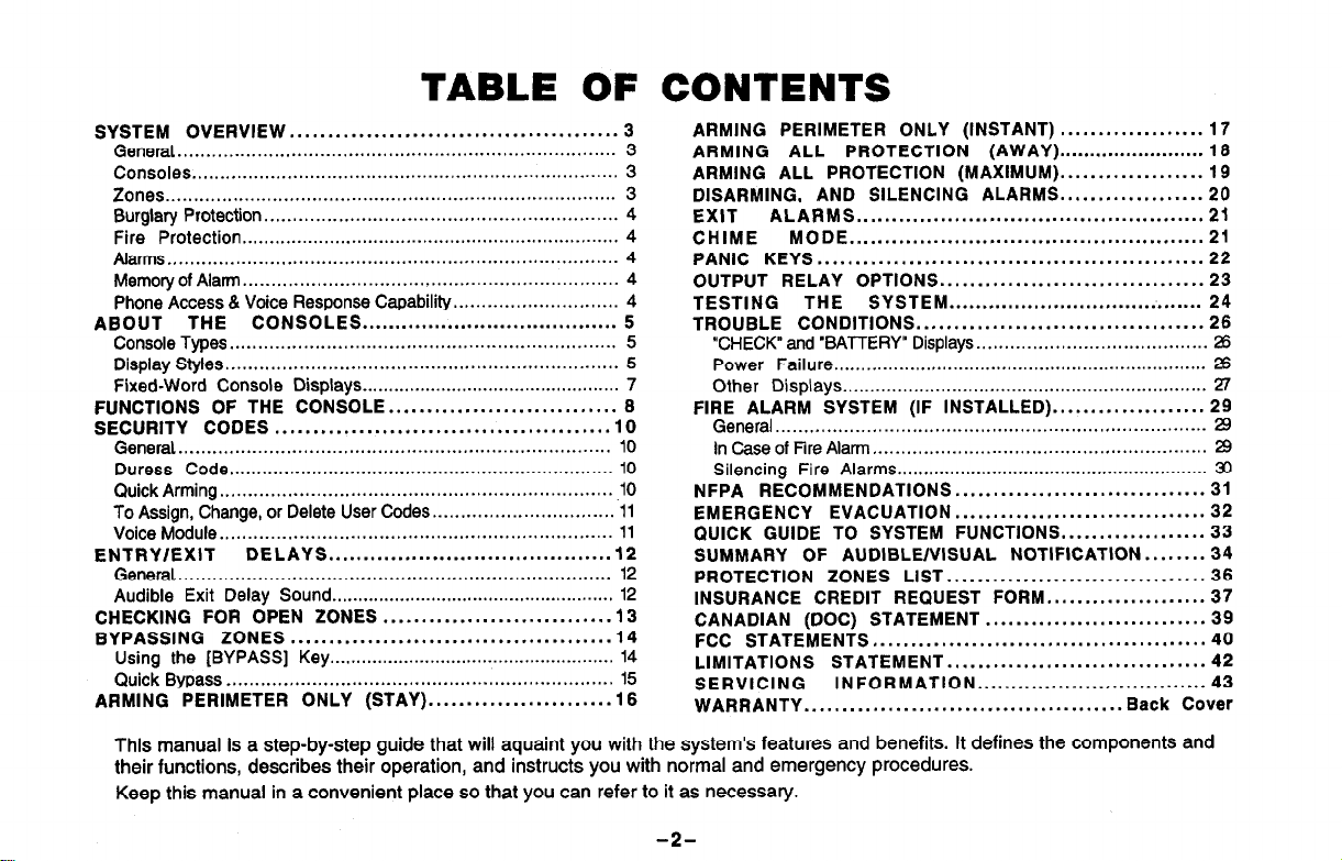
TABLE OF CONTENTS
SYSTEM OVERVIEW
ABOUT THE CONSOLES
FUNCTIONS OF THE CONSOLE..
SECURITY CODES
ENTRY/EXIT
CHECKING FOR OPEN ZONES
BYPASSING ZONES
ARMING PERIMETER ONLY
.............................................................................
General
Consoles
Zones
Burglary Protection..
Fire Protection
Alarms.,
Memory of
Phone Access 81 Voice Response Capability..
Console Types..
Display Styles
Fixed-Word Console Displays
General
Duress Code.. ....................................................................
Quick Arming
To Assign, Change, or Delete User Codes..
Voice Module
General
Audible Exit Delay Sound.. .................................................... 12
Using the [BYPASS] Key ......................................................
Quick Bypass
............................................................................
................................................................................
.............................................................................
Alarm..
............................................................................
.....................................................................
.....................................................................
............................................................................
...........................................
............................................................
.....................................................................
................................................................
..................................................................
.......................................
.....................................................................
................................................. 7
...........................
............................
............................................
..............................
DELAYS
....................................................................
.........................................
.............................
..........................................
(STAY). ....................... 18
3
3
3
3
4
4
4
4
4
5
5
5
8 FIRE ALARM SYSTEM (IF INSTALLED). ................... 29
10
10
10
10
11
11
12
12
.13
14
14
15
ARMING PERIMETER ONLY (INSTANT)
ARMING ALL PROTECTION
ARMING ALL PROTECTION (MAXIMUM). .................. 19
DISARMING, AND SILENCING
EXIT
CHIME
PANIC KEYS.. .................................................
OUTPUT RELAY OPTIONS.. .................................
TESTING THE SYSTEM.. .....................................
TROUBLE CONDITIONS.. ....................................
NFPA RECOMMENDATIONS.. ...............................
EMERGENCY EVACUATION..
QUICK GUIDE TO SYSTEM FUNCTIONS..
SUMMARY OF AUDIBLE/VISUAL NOTIFICATION
PROTECTION ZONES LIST.. ................................
INSURANCE CREDIT REQUEST
CANADIAN (DOC) STATEMENT
FCC STATEMENTS
LIMITATIONS STATEMENT
SERVICING
WARRANTY
ALARMS.. ................................................ 21
MODE.. ................................................. 21
“CHECK” and ‘BATTERY” Displays.. .......................................
Power Failure.. ...................................................................
Other
Displays.. .................................................................
General..
In Case of Fire Alarm
Silencing Fire Alarms
..........................................................................
...........................................................
...........................................................
............................................
INFORMATION.. ................................ 43
.......................................... Back Cover
(AWAY). ....................... 18
ALARMS.. ................. 20
............................... 32
FORM.. ................... 37
.............................
..................................
................... 17
.................
........ 34
22
23
24
26
26
26
27
29
29
30
31
33
36
39
40
42
This manual is a step-by-step guide that will aquaint you with the system’s features and benefits. It defines the components and
their functions, describes their operation, and instructs you with normal and emergency procedures.
Keep this manual in a convenient place so that you can refer to it as necessary.
-2-
SYSTEM OVERVIEW
GeneraI
Zones
Burglaty Protection
Congratulations on your ownership of an Ademco Security System. You’ve
made a wise decision in choosing it, for it represents the latest in security
protection technology today, including microcomputer technology to monitor all
system status. Ademco is the world’s largest manufacturer of security systems
and millions of premises are protected by Ademco systems.
Basically, this system offers you three forms of protection: burglary, fire and
emergency. Your system may consist of at least one console which provides full
control of system operation, various sensors such as motion detectors and door
and window sensing devices, plus a selected number of strategically placed
smoke or combustion detectors designed to provide early warning in case of
fire. Your system may also have been programmed to automatically transmit
alarm or status messages over the phone lines to a central alarm monitoring
station.
All system functions are controlled by your console(s), which are described in
the next section, ABOUT THE CONSOLES.
Your system’s sensing devices have been assigned to various “zones”. For
example, the sensing device on your Entry/Exit door may have been assigned
to zone 06, sensing devices on windows in the master bedroom to zone 10, and
so on. These zone numbers will appear on the display when an alarm or trouble
condition occurs.
The burglary protection portion of your system must be turned on or “armed”
before it will sense burglary alarm conditions and sound an alarm. Your system
can be armed in one of four modes: STAY, AWAY, INSTANT and MAXIMUM.
Refer to the ARMING THE SYSTEM sections for instructions in using these
modes of operation.
Your system also provides a CHIME mode for alerting you to the opening and
closing of doors and windows while the system is disarmed.
-3–
.
..—.
SYSTEM OVERVIEW
Fire Protection The fire protection portion of your security system (if used) is always on and will
sound an alarm if a fire condition is detected. Refer to the F/RE ALARM
SYSTEM section for important information concerning fire protection, smoke
detectors and planning emergency exit routes from your house.
Alarms when an alarmoccurs,boththe
a message at the console will identify the zone(s) causing the alarm. In addition,
if your system is connected to a central monitoring station, an alarm message
will be sent. To stop the alarm sounding, you simply disarm the system.
Memory Of Alarm When an alarm or trouble condition occurs, the console displays the number(s)
of the zone(s) that caused the problem, and displays the type of alarm or trouble
(ex. FIRE, ALARM, CHECK). The display remains until it is cleared by entering
the OFF sequence (security code + OFF key) twice.
Phone Access & If
Voice Response a Touch-tone phone, either on-premises or by call-in when away. The phone
Capability access feature will enable you to determine the status of the system and perform
your system includes a voice module it will permit you to access the system via
most system commands (including arming and disarming) over the phone.
-4-
console and external sounders will sound, and
ABOUT THE CONSOLES
General
Console Styles
Console Displays
Your consoles allow you to control all system functions. The consoles feature a
telephone style (digital) keypad and a Liquid Crystal Display (LCD) which
shows the nature and location of all occurrences.
The consoles feature a built-in sounder which emits alarm sounds during alarm
conditions and produces warning tones during entry (and exit, if soprogrammable) delay periods. The sounder also provides acknowledgement
tones when keys are pressed, and confirmation tones for successful command
entries.
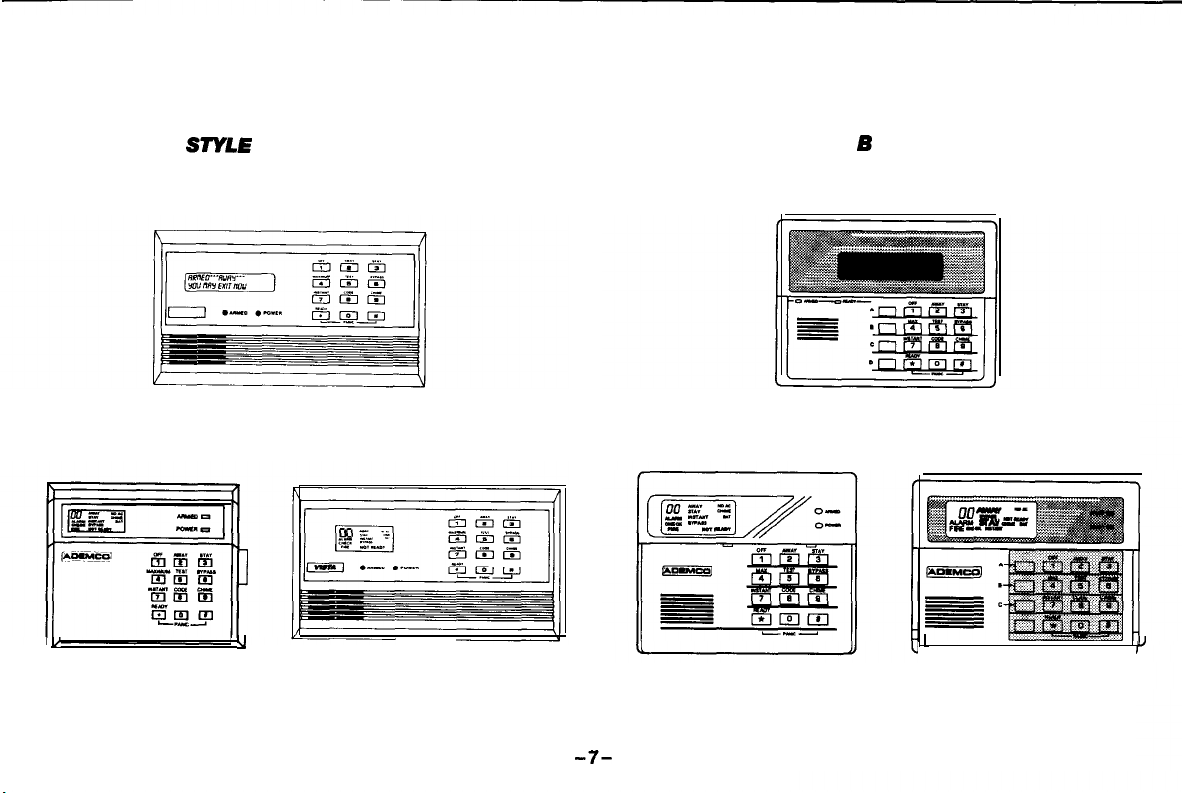
There are two basic styles of consoles, A and B, either of which may have been
used in your system (see page 7). Although different in appearance, both styles
are functionally the same. The keypads on style B consoles are located behind
a flip-down cover which can be removed, if desired,
There are two basic types of console displays, Alpha and Fixed-Word, either of
which may have been used in your system.
c Alpha Console Displays feature a 2-line, 32 character alphanumeric
Liquid Crystal Display (LCD) which can display the nature and location of all
occurrences in friendly English.
. Fixed-Word Console Displays are functionally similar to the Alpha
Consoles, except that their LCD display uses pre-designated (fixed) words to
identify the nature and location of occurrences. Words displayed on all FixedWord consoles are the same, except that their location in the display window
will vary with various models.
Unless stated otherwise, all commands and procedures described herein apply
equally to all consoles.
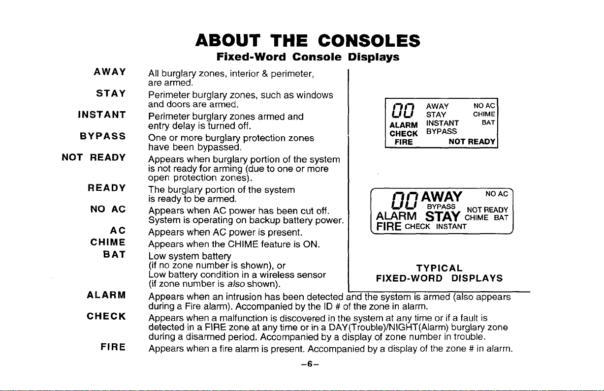
AWAY
STAY
INSTANT
BYPASS
NOT READY
READY
NO AC
AC
CHIME
BAT
ALARM
CHECK
FIRE
ABOUT THE CONSOLES
Fixed-Word Console Displays
All burglary zones, interior & perimeter,
are armed.
Perimeter burglary zones, such as windows
and doors are armed.
Perimeter burglary zones armed and
entry delay is turned off.
One or more burglary protection zones
have been bypassed.
t?u STAY
ALARM INSTANT
CHECK ‘YPASS
FIRE
AWAY
Appears when burglary portion of the system
is not ready for arming (due to one or more
open protection zones).
The burglary portion of the system
is ready to be armed.
Appears when AC power has been cut off.
System is operating on backup battery power.
Appears when AC power is present.
E
Appears when the CHIME feature is ON.
Low system battery
(if no zone number is shown), or
Low battery condition in a wireless sensor
(if zone number is
also shown).
FIXED-WORD DISPLAYS
I
TYPICAL
Appears when an intrusion has been detected and the system is armed (also appears
during a Fire alarm). Accompanied by the ID #of the zone in alarm.
Appears when a malfunction is discovered inthe system at any time or if a fault is
detected in a FIRE zone at any time or in a DAY(Trouble)/NIGHT(Alarm) burglary zone
during a disarmed period. Accompanied by a display of zone number in trouble.
Appears when a fire alarm is present. Accompanied by a display of the zone # in alarm.
–6–
NO AC
CHIME
BAT
NOT READY
ABOUT THE CONSOLES
SIYLE
5137AD ALPHA CONSOLE
u
4127
FIXED-WORD CONSOLES
A CONSOLES
u
4137AD
612716120
STYLE B CONSOLES
(SHOWN WITH KEYPAD COVER REMOVED)
6139 ALPHA CONSOLE
1
6137
FIXED-WORD CONSOLES
IJ
-7-
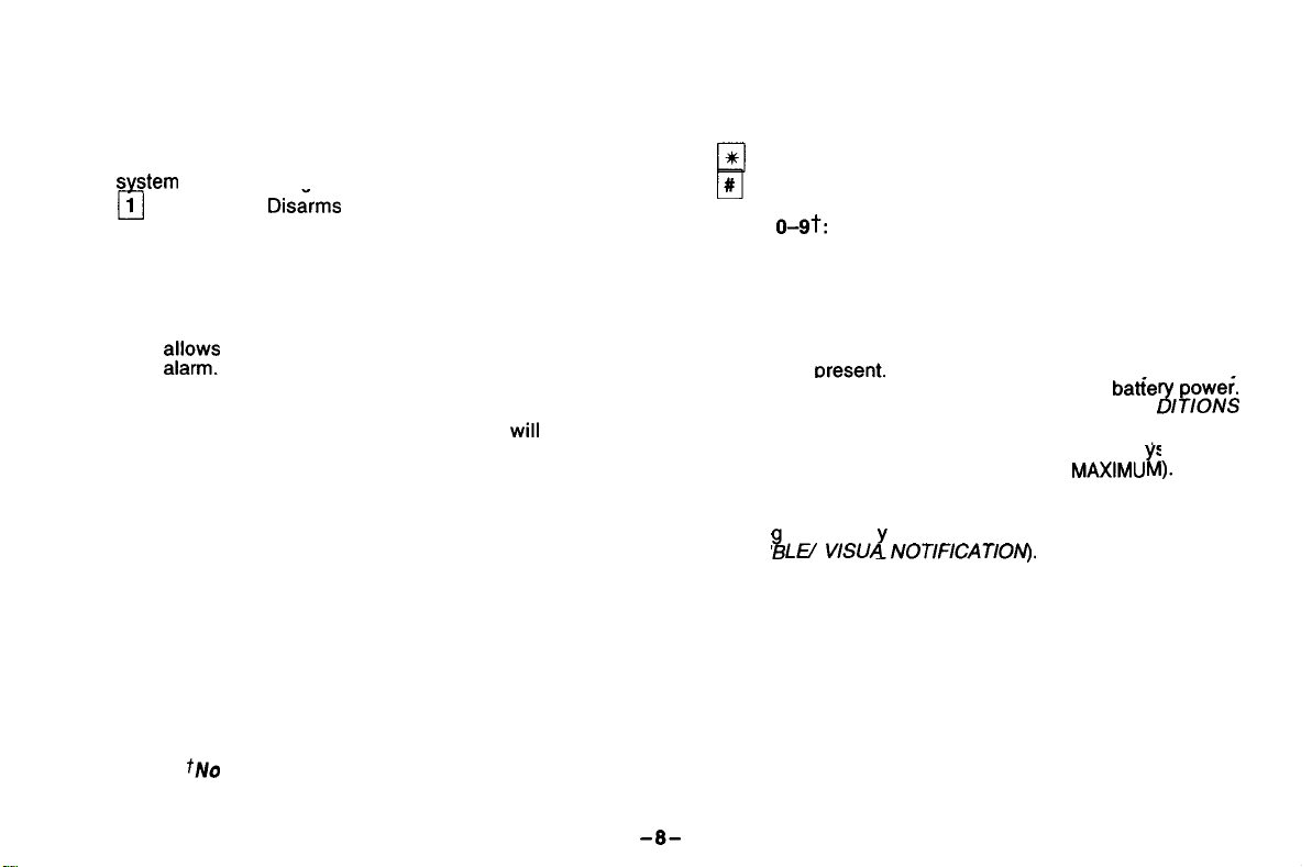
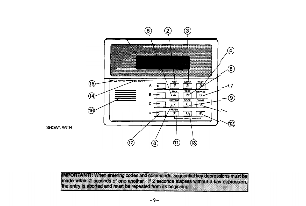
FUNCTIONS OF THE CONSOLE
SEE TYPICAL CONSOLE ON NEXT PAGE
1.
DISPLAY WINDOW: Displays protection zone ID and
sstem
status messaaes.
2.
3.
4.
5.
6.
7.
8.
10.
OFF KEY:
w
silences alarms and audible trouble indicators. and
clears visual display after problem’s correction.
AWAY KEY: Arms the entire burglary system,
q
perimeter and interior.
q
STAY KEY: Arms perimeter portion of burglary
system only. Interior protection is not armed, which
~1s~~
•J
MAXIMUM KEY: Arms in manner similar to AWAY
mode, but without the entry delay feature! thus providing maximum protection. An alarm
mediately upon opening any protection point, including
the main door.
q
TEST KEY: Tests the system and alarm sounder if
disarmed. Refer to TESTING THE SYSTEM section for
test procedures.
q
BYPASS KEY: Removes individual protection zones
from being monitored by the system.
q
INSTANT KEY: Arms in manner similar to STAY
mode, but without the entry delay feature. Entering
via the entry/exit door will cause an instant alarm.
9.
q
CODE KEY: Used to assign additional user codes for
other users of the system.
q
CHIME KEY: Turns CHIME mode on and off. When
on, the opening of windows or doors while the system is
disarmed will sound 3 beeps at the keypad(s).
tNo
Disirms
movement within premises without causing
te: Keys
when preceded by an entry of the security code (as described later).
burglary portion of the system,
q
through
q
-
*HREADY KEY: Displays all open protection zones.
11.
#
12.
13.
14. READY INDICATOR: (GREEN) Lit when the system is
WIII
occur im-
15.
16.
17.
each perform their associated companion functions (OFF, AWAY, STAY, etc.)
KEY: “Quick Arm” key permits ARMING of the system
without use of a security code (if so programmed).
KEYS
O-9T:
Used to enter your security code(s).
ready to be armed (no faults present). While the system is
disarmed, this indicator will go on and off as protection
zones are closed and opened.
Note: On some consoles there is, instead, a POWER
ARMED INDICATOR: (RED) Lit when the s stem has
been armed (STAY, AWAY, INSTANT or
INTERNAL SOUNDER: The built-in console sounder
mimics the alarm sounder during alarms, and will also “beep”
durin
AUDI
EMERGENCY (PANIC) KEYS:
Individual keys A, B, and C (key D not used).
On some consoles, these keys are not present and other
keys may be available for emergency functions.
For further information, refer to the PANIC KEYS section.
INDICATOR (GREEN) which is lit when AC power
is oresent. If the indicator is off, the svstem mav
stili be operating, but on its backup batie
See Power Failure in TROUBLE
section.
MAXIMU
certain s stem functions (see SUMMARY OF
LE/
VISLJA NOTIF~CAT~O~‘I-J.
i
r
CON
Kn
8
).
ITIONS
power.
-8-
1
Q
Q
0
Q
c9
/
/@
/7
0
-69
’
10
0
SHOWN WITH
KEYPAD COVER
REMOVED
Fixed-Word Consoles are functionally similar, except for screen displays.
TYPICAL ALPHA CONSOLE
. .
‘0
SECURITY CODES
General
Duress Code
Quick Arming
At the time of installation, your installer programmed a personal four-digit Master
code, known only to you and yours. This code is used to perform most system
functions, including arming and disarming of the system. As an additional safety
feature, temporary user codes can be assigned (see next page) for use by those
not having a need to know the Master code. Note that the Master code remains
in effect even when other user codes are assigned.
This feature is intended for use when you are forced to disarm or arm the system
under threat. When used, the system will act normally, but can silently notify the
central station of your situation, if that service has been provided.
The Duress code is the same as vour user code. except that the last digit is
increased bv one.
For example: If the normal security code is “1 2 3
4”,
the Duress security code is “1 2 3 5”.
Important: l This code is useful only when connected to a central station.
l
User codes that end in “9” (ex. 6349) cannot activate a duress
alarm (i.e., 6350 is not a duress alarm code).
If your system supports “Quick Arming”, the
“#”
key can be pressed in place of
the security code when arming the system. The security code is
required, however, when disarming the system.
always
SECUR1l’Y CODES
To Assign, Change,
or Delete
User Codes
Voice Module
1. Enter your Master code and press the CODE key,
2. Enter single-digit User Number for whom a code is to be assigned, changed,
or deleted.
3. If assigning or changing a user’s code, enter the desired 4-digit code
for use by that User Number. The console will beep once.
/f deleting a user’s code, perform steps 1 and 2 and then stop. In a few
moments the console will beep once, indicating that the existing code has
been deleted.
Important:
● Instruct other users to enter their codes carefully to avoid accidentally
entering the Duress code. If desired, other users can be assigned a code
ending in “9”, to prevent accidental Duress code entry.
. Temporary users should not be shown how to use any system function they
do not need to know (e.g., bypassing protection zones).
● Be sure user codes do not conflict with any Duress code.
If your system includes a voice module it will permit you to access the system via
a Touch-tone phone, either on-premises or by call-in when away. You can:
● Receive voice messages over the phone regarding system status.
. Arm and disarm the system and perform most function commands.
Complete information regarding the use of this feature is provided in a separate
manual: Phone Access User’s Guide that accompanies the voice module.
Notes:
. To turn off an alarm (with any system), enter: Security Code + [l/OFF] key.
● The “CALL-IN TAMPER” (“Cl”) console display and logic described in the
guide is not present in your system.
● The Relay Command Mode described in the guide is not active with your
system, but output relay actions may stillbe controlled if installer-programmed.
-11-
ENTRY/EXIT DELAYS
General Information
Exit Delay
Alerting Sound
Your system has preset time delays, known as exit delay and entry delay. When
you arm your system, exit delay gives you time to leave through the entry/exit
door without setting off an alarm. Entry delay gives you time to disarm the
system when you reenter through the entry/exit door. The system must be
disarmed, however, before the entry delay period ends, or an alarm will occur.
The console will beep slowly during the entry delay period, reminding you to
disarm the system,
You can also arm the system with no entry delay at all by using either INSTANT
or MAXIMUM arming modes. These
you are sleeping or while
you are away for extended periods of time.
modes can provide greater security while
If available for your system, and if so-programmed by your installer, when
arming AWAY (see page 18) or MAXIMUM (see page 19), slow beeps will
sound from the console during exit delay, turning to fast beeps during the final
five seconds of the delay time. -
See your installer for your delay times and record them here:
Exit Delay: ~] seconds
Entry Delay: ~] seconds
–12–
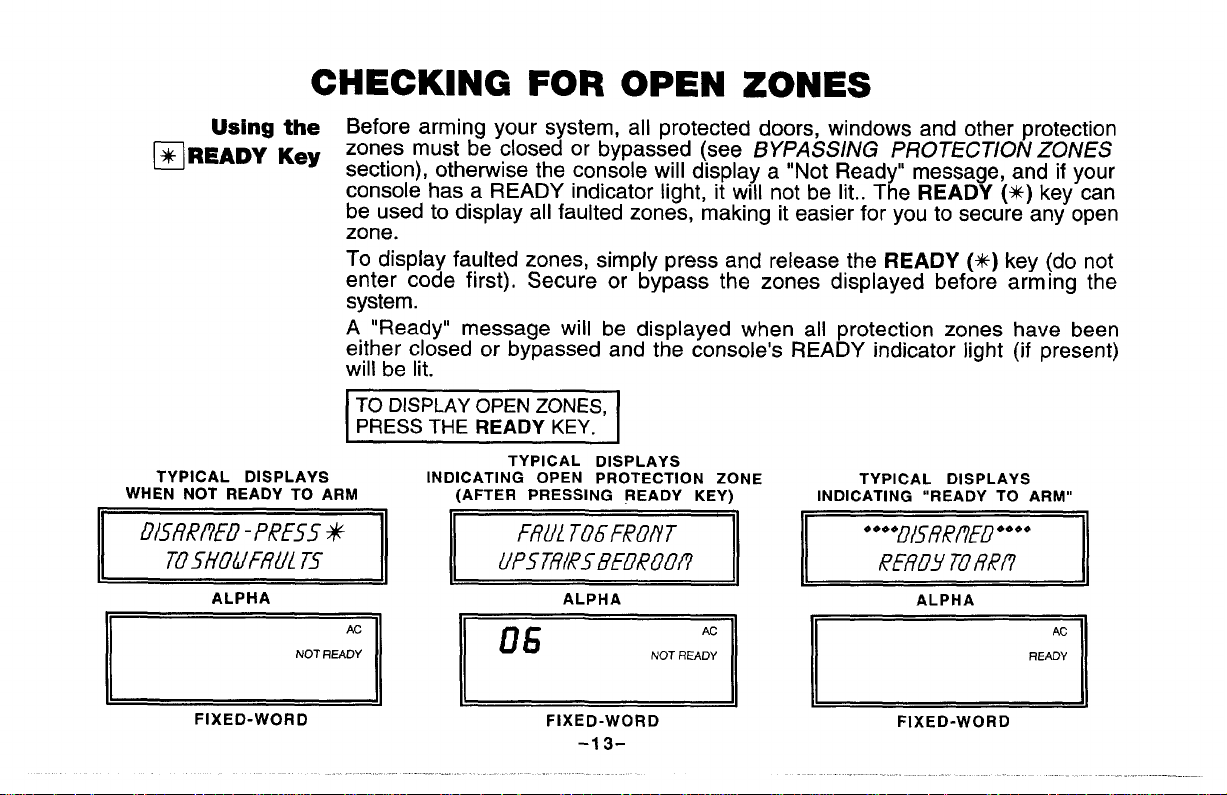
Using the Before arming your system, all protected doors, windows and other protection
❑READY Key
TYPICAL DISPLAYS
WHEN NOT READY TO ARM
D15fft?ff.D -PRESS ~
I
Tosffoumu[ 75
ALPHA
CHECKING FOR OPEN ZONES
zones must be closed or bypassed (see 13YPASS//VG PROTECT/ON ZONES
section), otherwise the console will display a “Not Ready” message, and if your
console has a READY indicator light, it will not be lit.. The READY (~) key can
be used to display all faulted zones, making it easier for you to secure any open
zone.
To display faulted zones, simply press and release the READY (+f) key (do not
enter code first), Secure or bypass the zones displayed before arming the
system.
A “Ready” message will be displayed when all protection zones have been
either closed or bypassed and the console’s READY indicator light (if present)
will be lit.
~
INDICATING OPEN PROTECTION ZONE
I
Ac
Nor FIEAoY
TYPICAL DISPLAYS
(AFTER PRESSING READY KEY)
AC
NOT READY
TYPICAL DISPLAYS
INDICATING “READY TO ARM”
ALPHA
FIXED-WORD
~
FIXED-WORD
-13-
FIXED-WORD
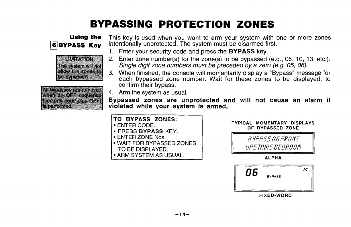
BYPASSENG PROTECTION ZONES
Using the
6 BYPASS Key
❑
This key is used when you want to arm your system with one or more zones
intentionally unprotected. The system must be disarmed first.
1. Enter your security code and press the BYPASS key.
2. Enter zone number(s) for the zone(s) to be bypassed (e.g., 06, 10, 13, etc.).
Single digit zone numbers must be preceded by a zero (e.g. 05, 06).
3. When finished, the console will momentarily display a “Bypass” message for
each bypassed zone number. Wait for these zones to be displayed, to
confirm their bypass.
4. Arm the system as usual.
Bypassed zones are unprotected and will not cause an alarm if
violated while your system is armed.
BYPASS ZONES:
TO
● ENTER CODE.
● PRESS BYPASS KEY.
● ENTER ZONE Nos.
● WAIT FOR BYPASSED ZONES
TO BE DISPLAYED.
● ARM SYSTEM AS USUAL.
TYPICAL MOMENTARY DISPLAYS
OF BYPASSED ZONE
ffYPR5506F(?OflT
uP5Tfli+e5BFoRoof?
ALPHA
FIXED-WORD
–14-

BYPASSING PROTECTION ZONES
Quick Bypass
If your system supports “Quick Bypass”, it allows you to easily bypass all open
(faulted) zones without having to enter zone numbers individually. This feature
is useful if, for example, you routinely leave certain windows open when arming
at night.
To use this feature, enter your security code, press the BYPASS key, then stop.
In a few moments, all open zones will be displayed along with a “Bypass”
message. Wait for all bypassed zones to be displayed, then arm the system as
usual.
SYSTEM CAN NOW BE ARMED
“READY TO ARM WITH ZONES BYPASSED”
WITH ZONE(S) BYPASSED.
TYPICAL DISPLAYS
~,
ALPHA
-,
FIXED-WORD
-15–

ARMING PERIMETER ONLY
WITH ENTRY DELAY ON
Using the
3 STAY Key
El
Use this key when you are staying inside, but expect someone to
use an entry/exit door later.
Enter ybur security code and press the STAY key.
1.
2.
The console beeps three times and displays the armed message. The red
ARMED indicator lights.
3.
The system arms. An alarm sounds immediately if a protected perimeter
window or non-entry/exit door is then opened, but you may otherwise move
freely throughout the premises.
Later arrivals can enter through an entry/exit door without causing
an alarm, but they must disarm the system within the entry delay
period to avoid sounding an alarm.
m ml
ALPHA
FIXED-WORD
–16-

ARMING PERIMETER ONLY
WITH ENTRY DELAY OFF
Using the
7 INSTANT Key
❑
Use this key when you are staying inside and do not expect anyone
to use an entry/exit door.
1. Enter your security code and press the INSTANT key.
2. The console beeps three times and displays the armed message.
ARMED indicator lights.
3, The system arms. An alarm’ sounds immediately if any protected perimeter
door or window is opened, but you may otherwise move freely throughout
the premises.
An alarm sounds immediately if anyone opens an entry/exit door.
(INCLUDING THE ENTRY/EXIT DOOR)
The red
EEEii3 ml
ALPHA
ml
FIXED-WORD
-17-
.— .-. ---- .-— ———— ————— -
WITH ENTRY DELAY ON
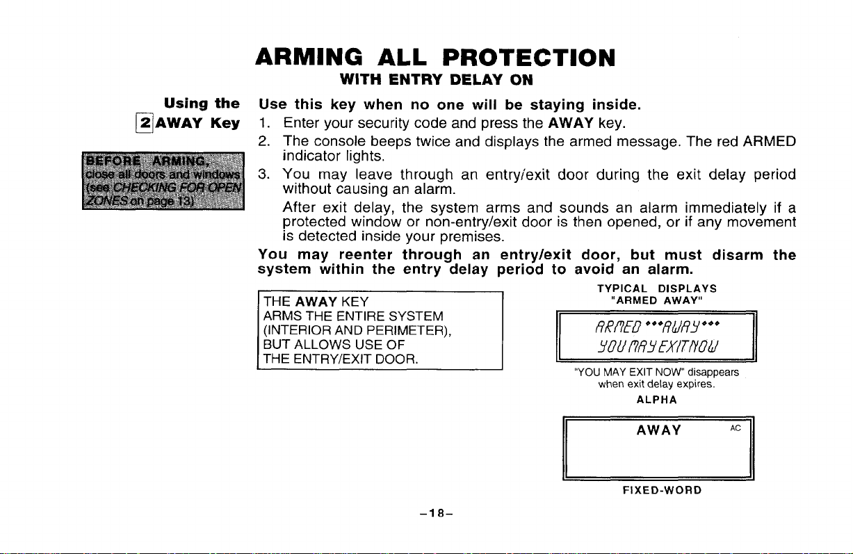
Using the
2 AWAY Key
❑
Use this key when no one will be staying inside.
Enter your security code and press the AWAY key.
1.
The console beeps twice and displays the armed message, The red ARMED
2.
indicator lights.
You may leave through an entrviexit
3.
door during the exit delay period
without causing an ala~m.
After exit delay, the system arms and sounds an alarm immediately if a
protected window or non-entry/exit door is then opened, or if any movement
is detected inside your premises.
You may reenter through an entry/exit door, but must disarm the
system within the entry delay period to avoid an alarm.
TYPICAL DISPLAYS
THE AWAY KEY
ARMS THE ENTIRE SYSTEM
(INTERIOR AND PERIMETER),
BUT ALLOWS USE OF
THE ENTRY/EXIT DOOR.
h
~
“ARMED AWAY”
“YOU MAY EXIT NOW disappears
when exit delay expires.
ALPHA
AWAY
FIXED-WORD
d
AC
–18-

ARMING ALL PROTECTION
WITH ENTRY DELAY OFF
Using the
4 MAXIMUM Key
❑
Use this key when the premises will be vacant for extended periods
of time such as vacations, etc., or when retiring for the night and no one will be
moving through protected interior areas.
Enter your security code and press the MAXIMUM key.
1.
The console beeps twice and displays the armed message. The red ARMED
2.
indicator lights.
You may leave through an entry/exit door during the exit delay period
3.
without causing an ala~m.
After exit delay, the system arms and sounds an alarm immediately if any
protected door or window is opened, or if any movement is detected inside
your premises.
An alarm sounds immediately, when someone reenters.
(INCLUDING THE ENTRY/EXIT DOOR
=
-19–
GEiiizl
“YOU MAY EXIT NOW disappears
—
TYPICAL DISPLAYS
when exit delay expires.
ALPHA
FIXED-WORD
DISARMING THE SYSTEM
AND SILENCING ALARMS
Using the
1 OFF Key
n
The OFF key is used to disarm the system and to
sounds.
To Disarm the System
Enter your securitv code and Dress the OFF kev. The “Ready” message will
be displayed, and the console will emit a single tone to confirm that the system
is disarmed.
To Silence a Burglary Alarm
SEE IMPORTANT NOTE AT LEFT!
Enter your security
warning tones of a Memory of Alarm). Note the zone in alarm on the console
display, and make that zone intact (close door, window, etc.). Now enter the
security code plus OFF sequence again to clear the console’s Memory of Alarm
display. If the display will not clear and does not provide a “Ready” message,
notify the alarm agency.
To Silence a Fire Alarm simdv p
needed to silence FIRE alarms). TO then clear the console’s Memory of Alarm
display, enter your security code and press the OFF key.
See page 29 for additional fire alarm information.
See the SUMMARY OF AUDIBLE/VISUAL NOTIFICATION section for
information which will help you to distinguish between FIRE
(lnterrupted/pulsed) and BURGLARY (Continuous/Steady) alarm
sounds.
code and mess the OFF kev to silence the alarm (or
ress the OFF kev (the security code is not
-20-
silence alarm and trouble

EXUT ALARMS
Exit Alarm Warning
Displays and Sounds
Your system may support and have been programmed for this feature.
When arming, if an exit or interior zone contains a fault during closing at the time
the exjt cfe/ay ends, the alarm sounder and console sound continuously to alert
you that an unwanted alarm can be prevented if you take action:
●
If you disarm the system during the entry delay period that wili immediately
Mow, the sound stops. The console displays “CANCELLED ALARM “or “CA”
as well as a zone indication. No messaae is transmitted to the central station.
●
If the system k NOT disarmed during the immediately following entry delay
period, ‘the sounds continue until the-system is disarmed (or alarm sounder
timeout occurs). The console displays “EXIT ALARM” or “EA” as well as a zone
indication. An “exit alarm” messaae will be sent to the central station.
h/ote: The latter “EXIT ALARM” conditions also result if an alarm from an exit
or interior zone occurs within two minutes after the end of an exit delay.
In any of the above cases, a second OFF
sequence (security code + OFF key)
will clear the console display.
CHIME MODE
Your system can be set to alert you to the opening of a door or window while it is
disarmed by using CHIME mode. When activated, three tones will sound at the
Console whenever a door or window is opened. Pressing the READY key will
display the open protection points.
To turn Chime Mode on, enter the security code and press the CHIME key.
The CHIME message will appear.
To turn Chime Mode off, enter the security code and press the CHIME key
again. The CHIME message will disappear.
-21.
.
.
. . ..

PANIC KEYS
Using
Panic Keys
(for manually activating
silent and/or
audible alarms)
● If connectedto centralstation.
CONSOLE KEYPAD
THESE KEYS NOT PRESENT
Your system may have been programmed to use special keys or combinations
of keys to manually activate emergency (panic) functions. The
might
Emergency, and Fire.
be programmed are: Silent Emergency, Audible Emergency, Personal
functions that
A silent emergency sends a silent alarm signal to the central station’, but
there is no audible alarm or visual display.
An audible emergency sends a signal to the central station* and sounds a
loud, steady alarm at your console(s) and at any external sounders that may be
connected (ALARM plus a zone number is also displayed).
A personal emergency alarm sends an emergency message to the central
station* and sounds at console(s), but not at external bells or sirens.
A fire alarm sends a fire alarm message to the central station* and uniquely
sounds at console(s) and external bells and sirens (FIRE plus a zone number is
also displayed).
I Also see Duress Code feature on page 10.1
OFF
AWAV
STAY
&m
‘b
TYPICAL
ON ALL CONSOLES _
LETfERED
PANIC d
KEYs
(“D IS NOT
usED, b
-3—
INSTAN
READ
r-l
CODE
CHIME
—
‘El
&.#
❑
PAIRED
PANIC
KEYS
-22-
PANIC KEYS
SEE YOUR INSTALLER
AND NOTE HERE
THE KEY(S)
& FUNCTION(S)
PROGRAMMED
FOR
YOUR SYSTEM
Programmed Ask your installer to provide information on any special system
(in response to
or manual entries)
Actions
zone activitv
CHECK IFIPANIC
ACTIVE KSY(S) FUNCTION NUMBER
n
n
n
I n l[ll&[*ll
n [*I & [w
n
[3] & [#]
[A]
[B]
[C]
CR
I
_SILENT,
_SILENT,
_SILENT,
_SILENT, _AUDIBLE,
_SILENT, _AUDIBLE,
_SILENT,
PROGRAMMED
_AUDIBLE, _PERSONAL,
_AUDIBLE, _PERSONAL,
_AUDIBLE, _PERSONAL,
_PERSONAL,
_PERSONAL,
_AUDIBLE, _PERSONAL,
ZONE
I
—FIRE
—FIRE
—FIRE
_FIRE I 95 I
—FIRE
—FIRE
●KEYS[A],[B], AND[C]ARE NOT PRESENT ONALLCONSOLES.
●KEY[D], IFPRESENTONYOUR CONSOLE, ISNOTACTIVE HERE,
OUTPUT RELAY OPT!ONS
actions that have
ACTION STARTED BY STOPPED BY
been programmed during installation.
95
07
96
07
96
–23–
.
TESTING THE SYSTEM
TO BE CONDUCTED WEEKLY
Using the
5 TEST Key
❑
The TEST key puts your system into Test mode, which allows each protection
point to be checked for proper operation.
Disarm the system and close all protected windows, doors, etc. The
1.
console’s READY message should be displayed and the READY indicator (if
present) should be lit.
2.
Enter your security code and press the TEST key.
3.
With some systems, as the Test mode is entered, the external siren or bell
will sound for one second and then turn off. With other systems, this sound
will occur, instead, as each zone is faulted in the following steps.
Each time a protection zone is faulted, the console sounds 3 beeps.
The console will sound a single beep every 40 seconds as a reminder that
the system is in the test mode.
If these sounds do not occur, call for service immediately.
Open and close each protected door and window in turn and listen for the
4.
required sounds The identification of each faulted protection point should
appear on the display.
Walk in front of any interior motion detectors (if used) and listen for the
5.
required sound as movement is detected. The identification of the detector
should appear on the display
when it is activated.
A/ofe: Wireless PIR (Passive Infrared) units will send signals out only if they
have been inactive for 3 minutes.
Follow the manufacturer’s instructions to test all smoke
6.
that all are functioning properly. The identification of each detector should
appear on the display
when each is activated.
-24-
detectors, to ensure
TESTING THE SYSTEM
7.
After all protection points have been checked and restored, there should be
no zone identification numbers displayed. If a problem is experienced
with any protection point (no confirming sounds, no display),
CALL FOR SERVICE IMMEDIATELY.
8.
Turn off the Test mode by
key.
entering the security code and pressing the OFF
I
WITH SOME SYSTEMS,
THE TEST MODE WILL BE AUTOMATICALLY TERMINATED AFTER 4 HOURS,
IF THE USER DOES NOT MANUALLY TERMINATE IT SOONER.
This insures that the Fire and Panic zones will not remain disabled.
d
-25-
1

TROUBLE CONDITIONS
“Check” and
“Battery” Displays
The word CHECK on the console’s display, accompanied by a “beeping” at the
console, indicates a trouble condition in the system.
To silence the beeping for these conditions, press any key.
1. A display of “CHECK” and one or more zone numbers indicates
that a problem exists with the displayed zone(s) and requires your attention.
If the CHECK display relates to a fire zone, CALL FOR SERVICE
IMMEDIATELY.
Determine if the zone(s) displayed are intact and make them so if they are
not. If the problem has been corrected, the display can be cleared if you
enter the OFF sequence (user code plus OFF key) twice. If the display
persists, CALL FOR SERVICE IMMEDIATELY.
2. If there are wireless sensors* in your system,
may also be caused
receiver from hearing a particular
IMMEDIATELY if this occurs.
by some change in the environment that prevents the
sensor. CALL FOR SERVICE
the CHECK condition
-1 -~
ALPHA
-~
-26–
FIXED-WORD

TROUBLE CONDITIONS
3.4.A display of
“BAT” with no zone number indicates that the main
standby battery in your control is weak. If this condition persists for
more than one day (with AC present), CALL FOR SERVICE.
A dis~lav of “BAT” with a zone number and a once ~er minute
“beeping;’ at the Console indicates that a low battery condit~on exists in
the wireless sensor displayed. Either replace the battery yourself, or
CALL FOR SERVICE. If the battery is not replaced within
CHECK display may occur.
Some wireless
sensors contain a non-replaceable long-life battery which re-
30 days, a
quires replacement of the entire unit at the end of battery life (e.g., 5802
Pendant and 5802CP Belt Clip Personal Emergency Transmitters and 5803
Wireless Key Transmitters).
Power Failure [f there is no console display at all, and the POWER indicator (if
present) is not lit,
system is inoperative. CALL FOR SERVICE IMMEDIATELY.
If the message ‘!AC LOSS” or “NO AC” is displayed, and the POWER
indicator (if present)
operating power for the system has stopped and the
is off, the Console is operating on battery power only.
If only some lights are out on the premises, check circuit breakers and fuses and
reset or replace as necessary. CALL FOR SERVICE IMMEDIATELY if AC
power cannot be restored.
Other Displays
Fixed-Word
Consoles
TROUBLE Conditions
dl:
If this remains displayed for more than 1 minute, your system is disabled.
CALL FOR SERVICE IMMEDIATELY.
cc:
The system is in communication with the central station for change of
function or status verification. If this message persists for more than
10 minutes, CALL FOR SERVICE IMMEDIATELY.
FC:
A communication failure with the central station has occurred.
CALL FOR SERVICE IMMEDIATELY.
Oc:
console is not receivina sianals from the control panel and sees an
The
open circuit. /f this rnessag; p%sts for more than 70 minutes, CALL
FOR SERVICE IMMEDIATELY.
Partitioned System
If your system is part of a Partitioned System, it can share one physical alarm
system between two different users, each with their own requirements (e.g., the
occupants of a two family house).
independently of the other, but from time to time display messages may appear
temporarily on a console which indicate the other partition is in use (e.g., during
testing by an installer). Do not be concerned, This is normal.
FOR SERVICING
INFORMATION,
SEE PAGE 43
-28-
When so-configured, each partition operates

FIRE ALARM SYSTEM
IF INSTALLED
General Your fire alarm system (if installed) is on 24 hours a day, for continuous
protection. In the event of an emergency, the strategically located smoke and
heat detectors will automatically send signals to
interrupted sound from the Console. An interrupted sound will also be produced
by optional exterior sounders. A FIRE
message will appear at your Console and
remain on until you silence the alarm.
your system, triggering a loud,
[n Case Of 1.
Fire Alarm
Should you become
aware of a fire emergency before your detectors sense
the problem, go to your nearest Console and manually initiate an alarm by
pressing the panic key pair assigned as FIRE emergency (if programmed by
the installer) as indicated on page 23.
Evacuate all occupants from the premises.
2.
If flames and/or smoke are present, leave the premises and notify your local
3.
Fire Department immediately.
4.
If no flames or smoke are apparent, investigate the cause of the alarm. The
zone number(s) of the zone(s) in an alarm condition will be displayed at the
Console.
TYPICAL FIRE EMERGENCY
-1
ALPHA
–29-
DISPLAYS
FIRE
FIXED-WORD

Silencing 1.
Fire Alarms
FIRE ALARM SYSTEM
IF INSTALLED
Silence
silence fire alarms). To clear the display, enter your code and press the OFF
key again (Memory of Alarm).
[f the Console’s fire indication does not clear after the second
2.
sequence, smoke detectors may still be responding to smoke or heat
producing objects in their vicinity. Investigate, and should this be the case,
eliminate the source of heat or smoke.
If this does not remedy the problem, there may still be smoke in the detector.
3.
Clear it by fanning the detector for about 30 seconds.
4.
When the problem has been corrected, clear the display by entering your
code and pressing the OFF key.
the alarm by pressing the OFF key (security code not needed to
OFF
-30–

NATIONAL FiRE PROTECTION ASSOCIATION
RECOMMENDATIONS ON SMOKE DETECTORS
-———. .– ..——.
General With regard to the number and placement of sr
subscribe to the recommendations contained in the
Association’s Standard #74 noted below.
Early warning fire detection is best achieved by the i
equipment in all rooms and areas of the household
a:
installed outside of each separate sleeping area, in tl
bedrooms and on each additional story of the fa
basements and excluding crawl spaces and unfinishc
In addition, it is recommended that the householder ~
smoke detectors
in the living room, dining roc
hallway(s), attic, furnace room, utility and storag(
attached garages.
BEST RESIDENTIAL
DETECTOR PLACEMENT
BETWEEN BEDROOMS
AND REST OF HOUSE
, Sm.ke l)elec[om 10, M,nm”
e Smoke Detectors 1., Addiim
MAXIMUM FLOOR
COVERAGE-
DETECTORS AT
TOP OF
STAIRWELLS
LW3 RM
BA.SEMEN7
I
m
#j
A U.at-Actrv8[6dD.t.ctm
-31-

EMERGENCY Evacuation
Steps to Safety
Establish and regularly practice a plan of escape
in the event of fire. The
following steps are recommended by the National Fire Protection Association:
Plan on your detector oryourinteriorand/or exterior sounders warning all
1.
occupants.
2,
Determine two means of escape from each room. One path of escape
should leadto the doorthat permits normal exit from the building. The other
may be a window, should your path be unpassable. Station an escape
ladder at such windows if there is a long drop to the ground.
3.
Sketch a floor plan of the building. Show windows, doors, stairs and
rooftops that can be used to escape. Indicate escape routes for each room.
Keep these routes free from obstruction and
routes
4.
Assure that all bedroom doors are shut while you are asleep. This will
prevent deadly
5.
Try the door. If the door is hot, check your alternate escape route. If the
is cool,
in every room.
smoke from entering while you escape.
open it cautiously. Be prepared to slam the door if smoke or heat
post copies of the escape
rushes in.
6.
in smoky areas, crawl close to floor, hold your breath, and/or cover mouth
and nose with a wet cloth.
7.
Escape quickly; don’t panic.
1.
Establish a common meeting place outdoors, away from your premises,
where everyone can meet and then take steps to contact the authorities and
account for those missing. Choose someone to assure that nobody returns
to the premises —
many die going back.
door
-32-
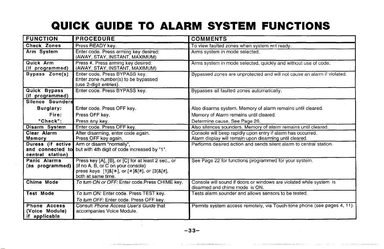
QUICK GUIDE TO ALARM SYSTEM FUNCTIONS
Fll Nf7T10N iPRr’)CFr)ll RF [ ~t7MilfulFNTC I
-------- ..
Check Zones
Arm System
Quick Arm Press #. Press arming key desired:
(if programmed) (AWAY, STAY, INSTANT, MAXIMUM)
Bypass Zone(s)
Quick Bypass Enter code, Press BYPASS key.
(if programmed)
Silence Sounders
Burglary: Enter code. Press OFF key.
Fire:
“Check”:
Disarm System Enter code, Press OFF key.
Clear Alarm After disarming, enter code again. Console will beep rapidly upon entry if alarm has occurred.
Memory Press OFF key again,
Duress (if active Arm or disarm “normally”, Performs desired action and sends silent alarm to central station.
and connected to but with 4th digit of code increased by “1”.
central station)
Panic Alarms Press key [A], [B], or [C] for at least 2 sec., or
(aa programmed) (if no A, B, or C on your console)
Chime Mode To turn ON or OFF: Enter code.Press CHIME key. Console will sound ifdoors or windows are violated while system is
Test Mode
Phone Access
(Voice Module)
if app Iicable
. ------ ----
Press READY key.
Enter code. Press arming key desired:
(AWAY, STAY, INSTANT, MAXIMUM)
Enter code. Press BYPASS key,
Enter zone number(s) to be bypassed
(use 2-digit entries).
Press OFF key.
Press any key.
press keys [l]&[#+], or [4$]&[#], or [3]&[#J,
both at same time.
To Ium 00/: Enter code, Press TEST key. Tests alarm sounder and allows sensors to be tested.
To turn OFF: Enter code, Press OFF key.
Consult Phone Access User’s Guide that
accompanies Voice Module.
. . ....... .. ,-
To view faulted zones when system @ ready.
Arms system in mode selected.
Arms system in mode selected, quickly and without use of code.
Bypassed zones are unprotected and will not cause an alarm if violated.
Bypasses all faulted zones automatically.
Also disarms system. Memory of alarm remains untilcleared.
Memory of Alarm remains until cleared.
Determine cause. See Page 26.
Also silences sounders. Memory of alarm remains until cleared.
Alarm display will remain upon disarming untilcleared.
See Page 22 for functions programmed for your system.
disarmed and chime mode is ON.
Permits system access remotely, via Touch-tone phone (see pages 4, 11).
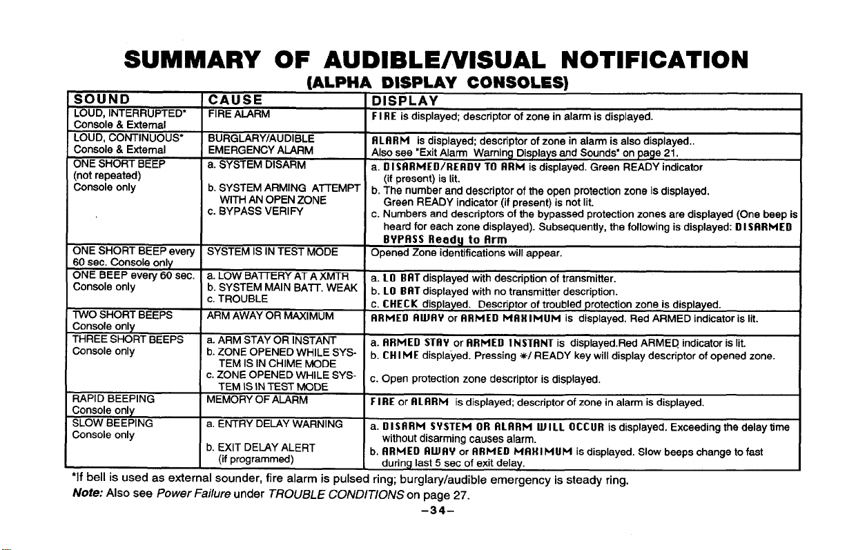
SUMMARY OF AUDIBLE/VISUAL NOTIFICATION
(A-HA DISPLAY CONSOLESI
SOUND CAUSE
LOUD, INTERRUPTED*
Console & External
LOUD, CONTINUOUS’
Console & External
ONE SHORT BEEP a. SYSTEM DISARM
(not repeated)
Console only
ONE SHORT BEEP every SYSTEM IS IN TEST MODE
60 sec. Console only
ONE BEEP every 60 sec.
Console only
TWO SHORT BEEPS
Console only
THREE SHORT BEEPS a. ARM STAY OR INSTANT
Console only b. ZONE OPENED WHILE SYS.
RAPID BEEPING MEMORY OF ALARM
Console only
SLOW BEEPING a. ENTRY DELAY WARNING
Console only
. .. . .. .
‘II Dell
IS used as external sounder, fire alarm is pulsed ring; burglary/audible emergency is steady ring.
Note: Also see Power Failure under TROUBLE CONDITIONS on page 27.
FIRE ALARM
BURGLARY/AUDIBLE
EMERGENCY AIJIRM
b. SYSTEM ARMING AITEMPT
WITH AN OPEN ZONE
c. BYPASS VERIFY
a. LOW BAITERY AT A XMTR
b. SYSTEM MAIN BATT. WEAK
c. TROUBLE
ARM AWAY OR MAXIMUM
TEM IS IN CHIME MODE
c. ZONE OPENED WHILE SYS-
TEM IS IN TEST MODE
b. EXIT DELAY ALERT
(if programmed)
.
DISPLAY
FIRE is displayed; descriptor of zone in alarm is displayed.
flLftRM is displayed; descriptor of zone in alarm is also displayed..
Also see “Exit Alarm Warning Displays and Sounds” on page 21.
a, OISflRMEE1/REtl LIY TO RRM is displayed. Green READY indicator
(if present) ie lit.
b. The number and descriptor of the open protection zone is displayed.
Green READY indicator (if present) is not lit.
c. Numbers and descriptors of the bypassed protection zones are displayed (One beep is
heard for each zone displayed). Subsequently, the following is displayed: 0 I SRRMELl
BYPRSS Ready
Opened Zone identifications will appear.
a. LO BFiTdisplayed with description of transmitter.
b. LO BfiT displayed with no transmitter description.
c. CHECK displayed. Descriptor of troubled protection zone is displayed.
FIRMEO FilLJR~or RRMED MRHIMUM is displayed. Red ARMED indicator is lit.
a. FIRMED STftY or RRMED INSTRNT is displayed.Red ARMEQ indicator is lit.
b. CHIME displayed. Pressing W READY key will display descriptor of opened zone.
c. Open protection zone descriptor is displayed.
FIRE or flLF!RM is displayed; descriptor of zone in alarm is displayed.
a. DISFIRM SYSTEM OR RLRRM WILL OCCUR is displayed. Exceeding the delay time
without disarming causes alarm.
b. RRMED RUJR~ or RRMED MRHIMUM is displayed. Slow beeps change to fast
during last 5 sec of exit delay.
–34–
to Rrm

SUMMARY OF AUDIBLE/VISUAL NOTIFICATION
-.
~
SOUND
LOUD, INTERRUPTED*
Console & External
LOUD, CONTINUOUS”
Console & External
ONE SHORT BEEP
(not repeated)
Console only
ONE SHORT BEEP
(once every 60 seconds)
Console only
ONE BEEP every 60 sec.
Console only
TWO SHORT BEEPS
Console only
THREE SHORT BEEPS
Console only
RAPID BEEPING
Console only
SLOW BEEPING
Console only
‘If bell
isused as externalsounder,firealarm ispulsedring;burglary/audibleemergencyissteadyring.
Note: Also see Power Failure, and Other Displays under TROUBLE CONDITIONS on page 27.
CAUSE
FIRE AURM
BURGLARY/AUDIBLE
EMERGENCY ALARM
a. SYSTEM DISARM
b. SYSTEM ARMING AITEMPT
WITH AN OPEN ZONE
c. BYPASS VERIFY
SYSTEM IS IN TEST MODE
a. LOW BAITERY AT XfvfTR
b. SYST. MAIN BAIT. WEAK
c. TROUBLE
ARM AWAY OR MAXIMUM
a. ARM STAY OR INSTANT
b. ZONE OPENED WHILE SYS-
TEM IS IN CHIME MODE
c. ZONE OPENED WHILE SYS-
TEM IS IN TEST MODE
MEMORY OF ALARM
a. ENTRY DELAY WARNING
b. EXIT DELAY ALERT
(ifprogrammed)
DISPLAY
FIRE and flLflRM are displayed; protectionzone in alarm is displayed.
flL13RM is displayed; protection zone in alarm is also displayed.
Also see ‘Exit Alarm Warning Displays and Sounds” on page 21.
a. Only RERDY isdisplayed. Green READY indicator (if present) is lit.
b. NOT REFIDV isdisplayed, open protection zone number is displayed.
Green READY indicator (if present) is not lit.
c. The bypassed protection zone numbers are displayed. (One beep for each number
displayed.) BYP13SSdisplayed.
Opened Zone identificationswill appear.
a. BAT displayad with ID number of transmitter.
b. BAT displayed with no transmitter ID
c. CHECK displayed. Troubled protection zone is displayed,
fitlJFIVand (if MAXIMUM) INSTFINT are displayad.
a ST1l’f and (if INSTANT) 1NSTfiNT are displayed. Red ARMED indicatoris lit.
b. CHIME displayed. Pressing W READY key will display opened zone.
C, openprotectionzonenumber is displayed.
FIRE and/or llLft RM is displayed; zone in alarm is displayed,
a. No display during dela~ Exceeding the delay time withoutdisarming causes alarm.
b. fifllll~ or (if MAXIMUM) FIUIFIY INSTftNT is displayed. Slow beeps change to fast
during last 5 sec of exit delay,
-35-
——-—-

One or more sensing devices will have been assigned by the installer of your alarm system to each of the various
PROTECTION ZONES LIST
protection zones in your system (a/though not every zone
Entry/Exit door may have been assigned to zone 06, sensing devices on windows in the master bedroom to zone 10, and
so on.
Zone numbers 07, 95 and 96 represent Console Keypad “Panic” alarm functions assigned by the installer (see Page 22).
Zone numbers 08 and 09 are reserved for Duress and Tamper signal reporting to the central station.
This chart may be used to record the specific zone number assignments for your system. Your installer will assist you in
recording this information.
PROTECTION ZONE DESCRIPTIONS
Zone
Description
01 17
02 18
03 19
04 20
05 21
06 22
07 Key B (OC x & #) Panic 23
08
09 –Tamper–
10
11
12
13
14
15
16
–Duress– 25
Zone
24
26
27 44
28
29
30
31
32
33
Description Zone Description
number cm he used). For example, the sensing device on your
Zone Description
34 51
35
36
37 54
38
39
40
41 58
42 59
43
45 62
46 63
47
48
49 96 Key C (OC 3 &#) Panic
50
52
53
55
56
57
60
61
95 Key A (OC 1 & +$)
Panic
J
–36–
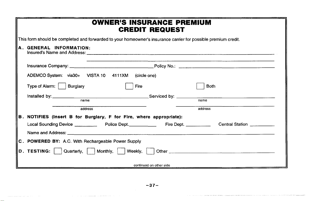
OWNER’S INSURANCE PREMIUM
CREDIT REQUEST
rhis form should be completed and forwarded to your homeowner’s insurance carrier for possible premium credit.
4.
GENERAL INFORMATION:
Insured’s Name and Address:
Insurance Company:
ADEMCO System: via30+
Type of Alarm:
Installed by:
NOTIFIES (Insert B for Burglary, F for
3.
Local Sounding Device
Name and Address:
.
POWERED BY: A.C. With Rechargeable Power Supply
w.
t).
TESTING:
❑ Burglary
❑ Quarterly, ❑ Monthly, ❑ Weekly, n Other
VISTA 10 411 IXM (circle one)
nama
addrass
Police Dept.
Policy No.:
❑ Fire
Serviced by:
Fire, where appropriate):
Fire Dept.
continuedon otherwde
-37-
❑ Both
nama
address
Central Station

OWNER’S lNSURANCE PREMIUM
CREDIT REQUEST (cont.)
:.
SMOKE DETECTOR LOCATIONS:
❑ Furnace Fioom
❑ 13asf?rnent ❑ Li.ingl%.fn
‘ . BURGLARY DETECTING DEVICE LOCATIONS:
~ l=rol-ltDoor
❑ I.t F1..rWindow.s ❑ Allwinclows
❑ Kitchen ❑ B(?ciromrls m Atii.
❑ Dining Room
❑ BasemerltDoor
❑ Rear c)ool’
❑ Interior Locations
❑ All Accessible Openings, Including Sl@igMs, Air Conditioners and Vents
; . ADDITIONAL PERTINENT INFORMATION:
~ Hall
❑ All Exterior Door.
Signature”
Date:
–38–
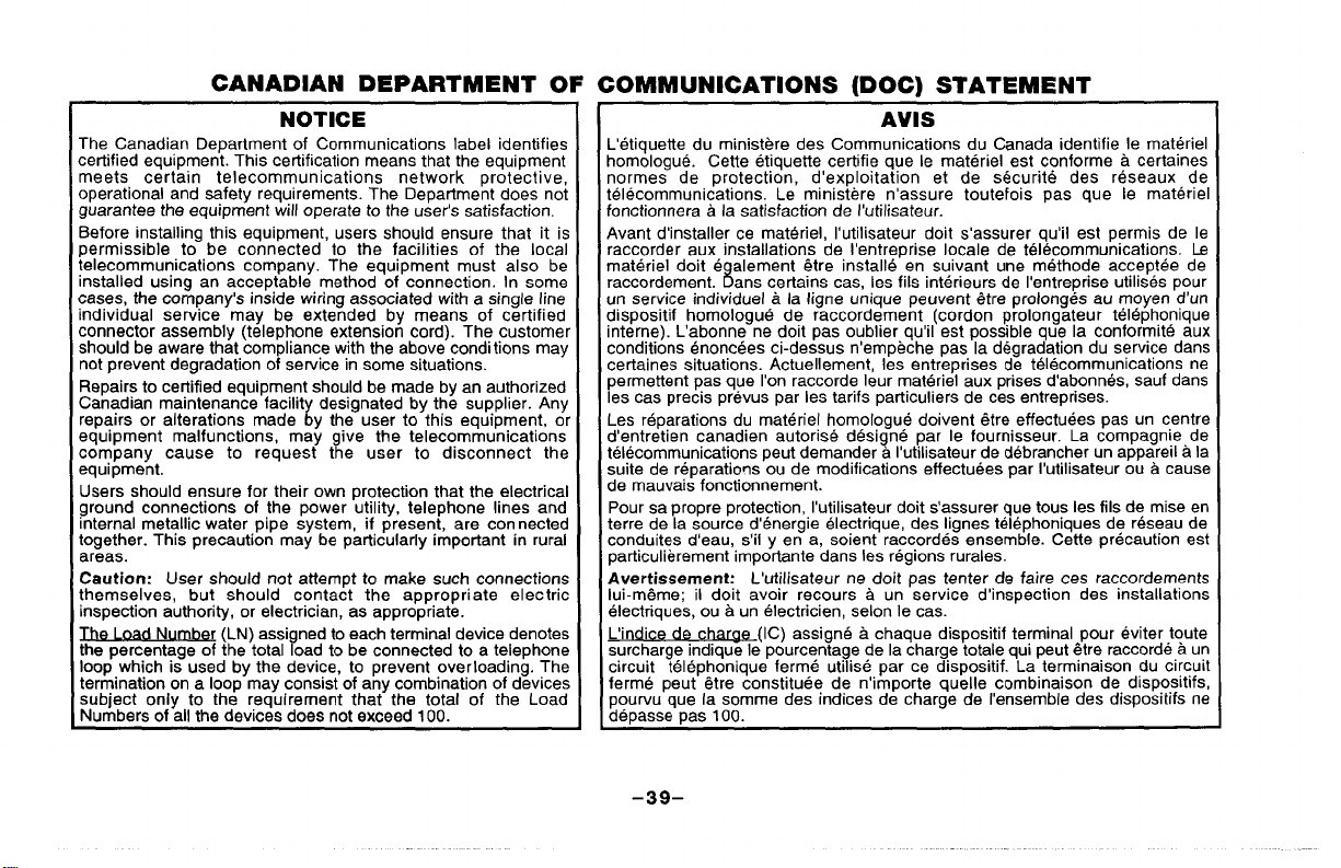
CANADIAN DEPARTMENT OF COMMUNICATIONS (DOC) STATEMENT
NOTICE
The Canadian Department of Communications label identifies
certified equipment. This cetilficafion means that the equipment
meets certain telecommunications network protective,
operational and safety requirements. The Department does not
guarantee the equipment will operate to the user’s satisfaction.
Before installing this equipment, users should ensure that it is
permissible to be connected to the facilities of the local
telecommunications company. The equipment must also be
installed using an acceptable method of connection. In some
cases, the company’s inside wiring associated with a single line
individual service may be extended by means of certified
connector assembly (telephone extension cord). The customel
should be aware that compliance withthe above conditions may
not prevent degradation of service in some situations.
Repairs to certified equipment should be made by an authorized
Canadian maintenance facilit designated by the supplier. Any
repairs or alterations made y the user to this equipment, 0[
equipment malfunctions, may give the telecommunications
company cause to request the user to disconnect the
equipment.
Users should ensure for their own protection that the electrical
ground connections of the power utility, telephone lines and
internal metallic water pipe system, if present, are con netted
together. This precaution may be particularly important in rural
areas.
Caution: User should not attempt to make such connections
themselves, but should contact the appropriate electric
inspection authority, or electrician, as appropriate.
The 1nad Numbe
the percentage of the total load to be connected to a telephone
loop which is used by the device, to prevent overloading. The
termination on a loop may consist of any combination of devices
subject only to the requirement that the total of the Load
Numbers of all the devices does not exceed 100.
r (LN) assigned to each terminal device denotes
i
AVIS
L’etiquefte du ministere des Communications du Canada identifie Ie materiel
homologue. Cefte etiquette certifie que Ie materiel est conforme a certaines
normes de protection, d’exploitation et de securite des reseaux de
telecommunications. Le ministere n’assure toutefois pas que Ie materiel
fonctionnera a la satisfaction de I’utilisateur.
Avant d’installer ce materiel, I’utilisateur doit s’assurer qu’il est permis de Ie
raccorder aux installations de I’entreprise locale de telecommunications. La
materiel doit e alement &tre installe en suivant une methode acceptee de
raccordement. ans certains cas, Ies fils interieurs de I’entreprise utilises pour
un service individual a la Iigne unique peuvent 6tre prolonges au moyen d’un
dispositif homologue de raccordement (cordon prolongateur telephonique
interne). L’abonne ne doit pas oublier qu’il est possible que la conformity aux
conditions enoncees ci-dessus n’empeche pas la degradation du service clans
cerfaines situations. Actuellement, Ies entreprises de telecommunications ne
permettent pas que I’on raccorde Ieur materiel aux prises d’abonnes, sauf clans
Ies cas precis prevus par Ies tarifs particuliers de ces entreprises.
Les reparations du materiel homologue doivent 6tre effectuees pas un centre
d’entretien canadien autorise designe par Ie fournisseur. La compagnie de
telecommunications peut demander a I’utilisateur de debrancher un appareil a la
suite de reparations ou de modifications affectuees par I’utilisateur ou a cause
de mauvais fonctionnement.
Pour sa propre protection, I’utilisateur doit s’assurer que tous Ies fils de mise en
terre de la source d’energie electrique, des Iignes telephoniques de reseau de
conduites d’eau, s’il y en a, soient raccordes ensemble. Cetfe precaution est
particulierement importance clansIes regions rurales.
Avertissement: L’utilisateur ne doit pas tenter de faire ces raccordements
lui-m~me; il doit avoir recours a un service d’inspection des installations
electriques, ou a un electrician, selon Ie cas.
L,i di
surcharge indique Ie pourcentage de la charge totaie qui peut ~tre raccorde a un
circuit telephonique ferme utilise par ce dispositif. La terminaison du circuit
ferme peut @tre constitute de n’importe quelle combinaison de dispositifs,
pourvu que la somme des indices de charge de I’ensemble des dispositifs ne
depasse pas 100.
de ch~
8
(IC) assigne a chaque dispositif terminal pour eviter toute
-39–

UL NOTICE: This is a “Grade A“ Residential System.
FEDERAL COMMUNICATIONS Commission (FCC) Part 15 STATEMENT
This eauirlment has been tested to FCC requirements and has been found acceptable for use. The FCC requires the following statement
for you} information:
This’’equipment generates and uses radio frequency energy and if not installed and used properly, that is, in strict accordance with the
manufacturer’s instructions, may cause interference to radio and television reception, It has been type tested and found to comply with
the limits for
reasonable protection against
occur in a particular installation. If this equipment does cause interference to radio or television reception, which can be determinedby
turningtheequipmentoffand
● If using an indoor antenna, have a quality outdoor antenna installed.
. Reorient the receiving antenna until interference is reduced or eliminated.
● Move the radio or television receiver away from the receiver/control.
. Move the antenna leads away from any wire runs to the receiver/controI.
● Plug the receiver/control into a different outlet so that it and the radio or television receiver are on different branch circuits.
If necessary, the user should consult the dealer or an experienced radio/television technician for additional suggestions. The user or
installer may find the following booklet prepared by the Federal Communications Commission helpful:
This booklet is available from the U.S. Government Printing Office, Washington, DC 20402.
The user shall not make any changes or modifications to the equipment unless authorized by the Installation Instructions or User’s
Manual. Unauthorized changes or modifications could void the user’s authority to operate the equipment.
a Class B computing device in accordance with the specifications in Part 15 of FCC Rules, which are desi ned to provide
such interference in a residential installation. However, there is no guarantee that inte erence willnot
on, the user is encouraged to try to correct the interference by one or more of the following measures:
“Interference Handbook
r?
In the event of telephone operational problems, disconnect the control by removing the plug from the RJ31 X wall jack. We recommend
IN THE EVENT OF TELEPHONE OPERATIONAL PROBLEMS
that your cetilfied installer demonstrate disconnecting the phones on installation of the system. Do not disconnect the phone
connection inside the control/communicator. Doing so will result in the loss of your phone lines. If the regular phone works correctly
after the control/communicator has been disconnected from the phone lines, the control/communicator has a problem and should be
returned for repair. If upon disconnection of the control/communicator, there is still a problem on the line, notify the telephone company
that they have a problem and request prompt repair service. The user may not under any circumstances (in or out of warranty) attempt
any service or repairs to the system. It must be returned to the factory or an authorized service agency for all repairs.
-40-

FEDERAL COMMUNICATIONS COMMISSION (FCC) Part 68 STATEMENT
This equipment complies with Part 68 of the FCC rules. On the front cover of this equipment is a label that contains, among other
information, the FCC registration number and ringer equivalence number (REN) for this equipment. If requested, this information must
be provided to the telephone company.
This equipment uses the following jacks:
The REN is used to determine the quantity of devices which maybe connected to the telephone line. Excessive RENs on the telephone
line may result in the devices not ringing in response to an incoming call. In most, but not all areas, the sum of the RENs should not
exceed five (5.0). To be certain of the number of devices that may be connected to the line, as determined by the total
thetelephonecompanyto determinethemaximum
If this equipment causes harm to the telephone network? the telephone company will notify you in advance that temporary discontinuance of service may be required. If advance notice is not practical, the telephone company will notify the customer as soon as
possible. Also, you will be advised of your right to file a complaint with the FCC if you believe necessary.
The telephone company may make changes in its facilities, equipment, operations, or procedures that could affect the operation of the
equipment. If this happens, the telephone company will provide advance notice in order for you to make the necessary modifications in
order to maintain uninterrupted service.
If trouble is experienced with this equipment, please contact the manufacturer for repair and warranty information. If the trouble is
causing harm to the telephone network, the telephone company may request you remove the equipment from the network until the
problem is resolved.
There are no user sewiceable components in this product, and all necessary repairs must be made by the manufacturer. Other repair
methods may invalidate the FCC registration on this product.
This equipment cannot be used on telephone company-provided coin service. Connection to Party Line Service is subject to state
tariffs.
This equipment
When programming or making test calls to an emergency number, briefly explain to the dispatcher the reason for the call. Perform such
activities in the off-veak hours: such as earlv mornina or late evenina.
is hearing-aid compatible.
An RJ31 X is used to connect this equipment to the telephone network.
RENs, contact
REN for the calling area.
-41-
WARNING!
THE LIMITATIONS OF THIS ALARM SYSTEM
While this system is an advanced design security system, it does not offer guaranteed protection against burglary or fire or other
emergency. Any alarm system, whether commercial or residential, is subject to compromise or failure to warn for a variety of reasons.
For examde:
●
Intruders may gain access through unprotected openings or have the technical sophistication to bypass an alarm sensor or
disconnect an alarm warning device.
●
Intrusion detectors (e.g. passive infrared detectors), smoke detectors, and many other sensing devices will not work without power.
Battery operated devices will not work without batteries, with dead batteries, or if the batteries are not put in properly. Devices
powered solely by AC will not work if their AC power supply is cut off for any reason, however briefly.
✎
Signals sent by wireless transmitters may be blocked or reflected by metal before they reach the alarm receiver. Even if the signal
path has been recently checked during a weekly test, blockage can occur if a metal object is moved into the path.
D
A user may not be able to reach a panic or emergency button quickly enough.
.
While smoke detectors have played a key role in reducing residential fire deaths in the United States, they may not activate or
provide early warning for a variety of reasons in as many as 35% of all fires, according to data published by the Federal Emergency
Management Agency. Some of the reasons smoke detectors used in conjunction with this System may not work are as follows.
Smoke detectors may have been improperly installed and positioned. Smoke detectors may not sense fires that start where smoke
cannot reach the detectors, such
not sense a fire on another level of a residence or building. A second floor detector, for example, may not sense a first floor or
basement fire. Moreover, smoke detectors have sensing limitations. No smoke detector can sense every kind of fire every time. In
general, detectors may not always warn about fires caused by carelessness and safety hazards like smoking in bed, violent
explosions, escaping gas, improper storage of flammable materials, overloaded electrical circuits, children playing with matches, or
arson. Depending upon the nature of the fire and/or the locations of the smoke detectors, the detector, even if it operates as
anticipated, may not provide sufficient warning to allow all occupants to escape in time to prevent injury or death.
●
Passive Infrared Motion Detectors can only detect intrusion within the designed ranges as diagramed in their installation maflUal.
Passive Infrared Detectors do not provide ~olumetric area protection, They
only be detected in unobstructed areas covered by those beams, They cannot detect motion or intrusion that takes place behind
walls, ceilings, floors, closed doors! glass partitions, glass doors, or windows. Mechanical tampering, masking, painting or spraying
of any material on the mirrors, windows or any part of the optical system can
Detectors sense changes in temperature; however, as the ambient temperature of protected area approaches the temperature range
of 90° to 105°F (32° to 40”C), the detection performance can decrease.
as in chimneys, in walls, or roofs, or on the other side of closed doors. Smoke detectors also may
do create-multiple beams of protection, and intrusion can
reduce their detection ability. Passive Infrared
(continued)
-42-

(continued) WARNING! THE LIMITATIONS OF THIS ALARM SYSTEM
l
Alarm warning devices such as sirens, bells or horns may not alert people or wake up sleepers if they are located on the other side of
closed or partly open doors. If warning devices sound on a different level of the residence from the bedrooms, then they are less
likely to waken or alert people inside the bedrooms. Even persons who are awake may not hear the warning if the alarm is muffled
from a stereo! radio, air conditioner or other appliance, or by passing traffic. Finally, alarm warning devices, however loud, may not
warn hearing-Impaired people or waken deep sleepers.
l
Telephone lines needed to transmit alarm signals from a premises to a central monitoring station may be out of service or temporarily
out of service. Telephone lines are also subject to compromise by sophisticated intruders.
l
Even if the system responds to the emergency as intended, however, occupants may have insufficient time to protect themselves
from the situation. In the case of a monitored alarm system, authorities may not respond appropriately.
l
This equipment, like other electrical devices, is subject to component failure. Even though this equipment is designed to last as long
as 10 years, the electronic components could fail at any time.
The most common cause of an alarm system not functioning when an intrusion or fire occurs is inadequate maintenance.
system
should be tested weekly to make sure all sensors and transmitters are working properly.
This alarm
Wireless transmitters (used with some systems) are designed to provide long battery life under normal operating conditions. Longevity
of batteries may be as much as 4 to 7 years, depending on the environment, usage, and the specific wireless device being used.
External factors such as humidity, high or low temperatures, as well as large swings in temperature, may all reduce the actual battery
life in a given installation. This wireless system, however, can identify a true low battery situation, thus allowing time to arrange a
change of battery to maintain protection for that given point within the system.
Installing an alarm system may make one eligible for lower insurance rates, but an alarm system is not a substitute for insurance.
Homeowners, property owners and renters should continue to act prudently in protecting themselves and continue to insure their lives
and property.
We continue to develop new and improved protection devices. Users of alarm systems owe it to themselves and their loved ones to
learn about these developments.
-----m-m-_- -------- - -- - --
SERVICING INFORMATION
Your local authorized service representative is the person best qualified to service your alarm system. Arranging a
regular program with that person is advisable. Your local service representative is:
NAME:
ADDRESS:
PHONE:
-43-

ADEMCO ONE YEAR LIMITED WARRANTY
Alarm Device Manufacturing Company, a Division of Pittway Corporation, and its divisions, subsidiaries and affiliates (“Seller”), 165
Eileen Way, Syosset, New York 11791, warrants its security equipment (the “product”) to be free from defects in materials and
workmanshtp for one year from date of original purchase, under normal use and service. Seller’s obligation is limited to repairing or
replacing, at its option, free of charge for parts, labor, or transportation, any product proven to be defective in materials or
workmanship under normal use and service. Seller shall have no obligation under this warranty or otherwise if the product is altered or
improperly repaired or serviced by anyone other than the Seller. In case of defect, contact the security professional who installed and
maintains your security equipment or the Seller for product repair.
This one ear Limited Warranty is in lieu of all other express warranties obligations or liabilities. THERE ARE
WARRANKES WHICH EXTEND BEYOND THE FACE HEREOF ANY IMPLIED WARRANTIES OBLIGATIONS OR LIABILITIES MADE
BY SELLER IN’CONNECTION WITH THIS PRODUCT, INCLUDING ANY IMPLIED WARRANTY’OF MERCHANTABILITY, OR FITNESS
FOR A PARTICULAR PURPOSE OR OTHERWISE, ARE LIMITED IN DURATION TO A PERIOD OF ONE YEAR FROM
ORIGINAL PURCHASE. ANY ACTION FOR BREACH OF ANY WARRANTY, INCLUDING BUT NOT LIMITED TO ANY IMPLIED
WARRANTY OF MERCHANTABILITY, MUST BE BROUGHT WITHIN 12 MONTHS FROM DATE OF ORIGINAL PURCHASE. IN NO CASE
SHALL SELLER BE LIABLE TO ANYONE FOR ANY CONSEQUENTIAL OR INCIDENTAL DAMAGES FOR BREACH OF THIS OR ANY
OTHER WARRANTY, EXPRESS OR IMPLIED, OR UPON ANY OTHER BASIS OF LIABILITY WHATSOEVER, EVEN IF THE LOSS OR
DAMAGE IS CAUSED BY THE SELLER’S OWN NEGLIGENCE OR FAULT. Some states do not allow limitation on how long an implied
warranty lasts or the exclusion or limitation of incidental or consequential damages, so the above limitation or exclusion may not apply
to you.
Seller does not represent that the product may not be compromised or circumvented; that the product will prevent any personal injury or
property loss by burglary, robbery, fire or otherwise; or that the product will in all cases provide adequate warning or protection. Buyer
understands that a properly installed and maintained alarm may only reduce the risk of a burglary, robbery, frre or other events
occurring without providing an alarm, but it is not insurance or a guarantee that such will not occur or that there will be no personal injury
or property loss as a result. CONSEQUENTLY, SELLER SHALL HAVE NO LIABILITY FOR ANY PERSONAL INJURY, PROPERTY
DAMAGE OR OTHER LOSS BASED ON A CLAIM THE PRODUCT FAILED TO GIVE WARNING. HOWEVER, IF SELLER IS
ABLE, WHETHER DIRECTLY OR INDIRECTLY, FOR ANY LOSS OR DAMAGE ARISING UNDER THIS LIMITED
OTHERWISE, REGARDLESS OF CAUSE OR ORIGIN, SELLER’S MAXIMUM LiABlLlTY SHALL NOT IN ANY CASE EXCEED THE
PURCHASE PRICE OF THE PRODUCT, WHICH SHALL BE THE COMPLETE AND EXCLUSIVE REMEDY AGAINST SELLER. This
warranty gives you specific legal rights, and you may also have other rights which vary from state to state. No increase or alteration,
written or verbal, to this warranty is authorized.
NO EXPREbS
THE DATE OF
HELD LI-
WARRANTY OR
N7229 7194
A Division of Pittway Corporation
165 Eileen Way, Syosset, New York 11791
Copyright 0 1994 PITfWAY CORPORATION
 Loading...