

Honeywell Viewguard DUAL AM FAI, Viewguard DUAL FAI Installation Instructions Manual
Viewguard Series DUAL
033440 / 033450
Viewguard DUAL AM FAI
033441 / 033451
Viewguard DUAL FAI
Fig. 2
P01715-10-007-00
24.10.2007
GB
E
F
NL
Installation Instructions
Instrucciones de instalación
Notice d'installation
Installatievoorschriften
GB
E
F
Page 2 Página 4 Page 6
NL
Kant 8
Fig. 1
Fig. 3 Fig. 4
Fig. 6
2,5m
5m
10m 15m0m
0°
10°
20°
30°
40°
10°
20°
30°
40°
0m
9m
9m
5m 10m 15m0m
0 (Fig. 5/1)°
A
C
B
D
b
A
B
D
C
a
a
DUAL AM FAI
DUAL FAI
Fig. 5
+/-0°
45°
45°
5/1 5/2 5/3 5/4
a)
b)
c)
2 Installation Instructions Viewguard DUAL / AM FAI
1. Introduction
2. Installation Guide line
3. Installation
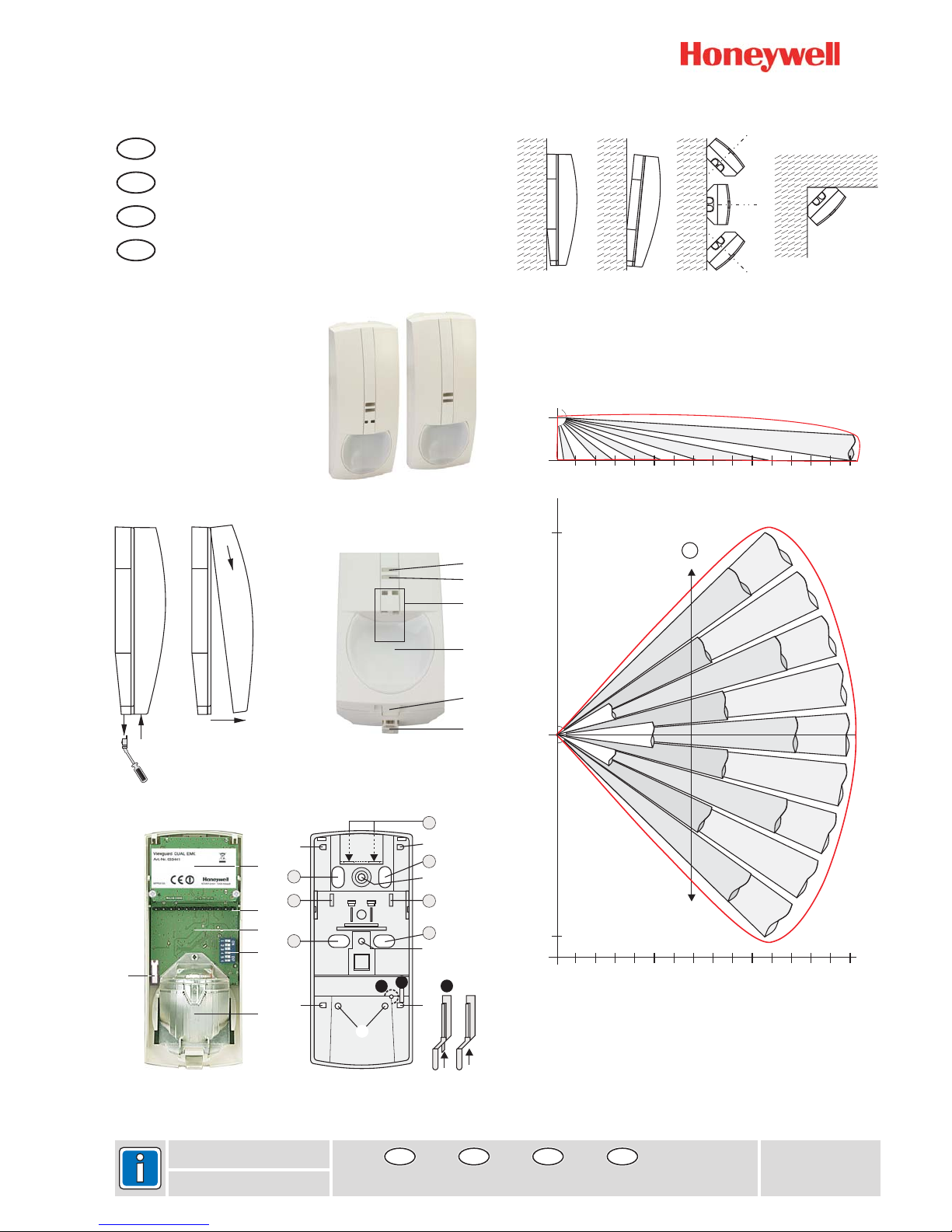
The Viewguard DUAL motion detector comprises two systems that operate fully
independently: Passive infrared detector plus Microwave detector. The functioning principle
of the detector is based on the intelligent linkage of a passive infrared sensor and
microwave. This type of linking renders the detectors particularly insensitive to air and
thermal turbulences. (Microwave module see Fig. ).
They are delivered with the following main features:
Volumetric mirror optic
, see Fig. , (only 033440/450)
FAI (First Alarm Indication):
Selectable range and sensitivity
Memory function
Selectable range and sensitivity
Self-test (only 033440 )
Monitoring of operating voltage
Tamper and back tamper
Maximum sensitivity is achieved when mounted crosswise to the horizontal detection
zones of the PIR sensors. Therefore, select a mounting site that runs crosswise to the
expected direction of motion. (See Fig. ).
Minimum distance to ceiling: 2 cm
* Mounting above radiators
* Mounting near air discharge openings (e.g. air conditioning systems)
* Direct sunlight
* Mounting near to fluorescent lamps
* Mounting near to light bulbs
(see Fig. 1)
If necessary, break the seal with a small screwdriver or similar object and pull downward
. Press the notch (at the bottom in the middle, see Fig. ) slightly inward and
press off the front of the housing . Lift off the housing front .
• 0° Vertical see Fig. 5/1 Fig.
• Vertical at a 3° downward angle see 5/2 Fig.
• Horizontal at a 45° angle to the left or right see 5/3 Fig.
• Corner mounting see 5/4 Fig.
The detector can be mounted by using the optional swivel bracket (033390 or 033588, see
"Accessories").
(See 4)
For surface mounted wiring
For flush mounted wiring
For use with adjusting hinge
For strain relief with cable strap
3-
(see Fig. 3- , Fig. 6)
2-
Microwave sensor inactive in the "disarmed" state.
When multiple detector on a single zone, Indicate the first detector in alarm
/450
6-A
2-
4Fig. 4Fig. 4Fig. 4-
Fig.
(see Fig. 4)
Required for installation according to DIN CLC/TS 50131-2-4 grade 3.
The backtamper can be used if installed as illustrated in Fig. 5/1, 5/2, 5/3a, 5/3b and 5/4.
Tappet for backtamper. Remove the pin at the tappet, if the backtamper is
being used (see illustration)
Protective cover for back-tamper (on the rear). Remove, when mounting as
per Fig. 5/3a or 5/4
-
-
-
-
-
-
-
-
-
Avoid:
Open housing
Mounting options Screw on position
Cabling, strain relief
A
B, C
C
D
Anti-masking up to 30 cm from the detector
-
Backtamper
a
b
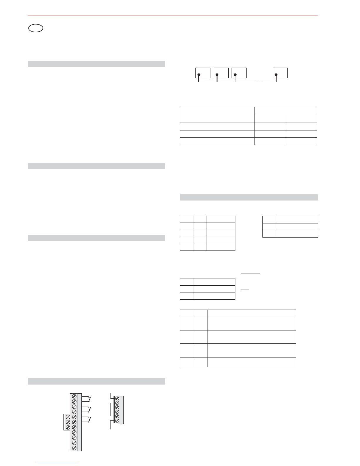
4.2 Easy Logic operating mode without FAI function
The control signals "Walk test", "disarmed" and "FAI" are not connected. In this operating
mode no alarm indication, no FAI function and no memory is available.
The DIP-switches S4, S5 and S6 must be in position "ON".
The Microwave sensor is always active.
Detector 1FDetector 2 Detector 3
Detector 20
F
F
F
Function of inputs:
(Pull-up resistors in the detector)
Function
a) armed
b) disarmed
c) walk test, clear alarm indication
High
Low
Inputs
walk test "T" arm/disarm "U"
High
High
Low
Low
4.1 Viewguard operating mode with FAI function
(FAI = irst larm ndication)
The FAI connections "F" of all detectors are connected to one another. A connection to the
control panel is not required. The LED flashes on the detector that triggers first, the LED
light on the subsequently triggered detectors (see 6. "LED indication").
FA I
FAI logic:
Close housing
Apply operating voltage
Walk test in Easy Logic mode
See Fig. 1 in reverse order. Ensure that the housing is closed correctly and locked into
position. Do not insert the seal to lock the housing until installation is completed
After applying the operating voltage, the detector automatically performs an initialisation.
Both LEDs flash (see 6.). . After max.
60 seconds the detector is ready for operation. After this period, do not change anything in
the close vicinity (up to 50 cm) that may influence the reflected light.
The detector is automatically in for approx. after initialising is
completed. Conduct the walk test within this time period. LED indication see 6.
The detector is operationally ready after the 10 minutes have expired.
Do not enter the Anti-Mask range during initialisation
walk test mode 10 minutes
5. Setting
DIP-switches: see Fig. 3-
S3 Sensitivity
ON normal
OFF high
S1 S2 Range
OFF OFF 8 m
ON OFF 11 m
OFF ON 13 m
ON ON 15 m
S4 S6 Operating mode ()Anti-Mask only 033440/
ON ON Easy Logic mode only (see 4.2)
ON OFF Viewguard mode with FAI
OFF OFF Viewguard mode with FAI
OFF ON
450
Anti-Mask always active
Anti-Mask always active
Anti-Mask inactive in "armed" state
N.A.
S5 Fault/Cover
ON do not save
OFF save
Memory:
Do not save:
Save:
Fault/cover signal is automatically cleared after
elimination of the fault/cover.
Not possible in Easy Logic mode!
Fault/cover signal remains saved in the detector
until it is cleared via control panel.
4. Connection diagram
Installation Instructions
Viewguard Series DUAL
GB
Fault Tamper Alarm T U F
+
Fault
Alarm
Tamper
Walk test
0V
+12VDC
Spare terminals for
end of line resistors
arm/disarm
FAI
Fault Tamper Alarm
If thecontrolpanel hasno fault input,
the "Alarm" and "Fault" outputs can
be connectedin series.
PIR and MW operate automatically
with the same range.

3
Installation Instructions Viewguard DUAL / AM FAI
7. Technical specification
Operating voltage Vnom 12 V DC
Operating voltge range 8.0 V to 15 V DC
Current consumption at Vnom=12 V DC 6.6 mA
Range (programmable): 8 / 11 / 13 / 15 m
PIR and MW together
PIR sensor temperature-compensated
PIR sensitivity (programmable): normal / high
(only 033440/450) up to 30 cm
Frequency microwave:
- 033440 / 033441 9.35 GHz (X band)
- 033450 / 033451 10.587 GHz (X band)
Installation position vertical, optics at bottom
Alarm contact:
- Contact rating 15 V DC / 0.1 A
- Internal resistance 25
- Contact position open in the event of alarm
Fault contact:
- Contact rating 15 V DC / 0.1 A
- Internal resistance 25
- Contact position open in the event of fault
Tamper contact:
- Contact rating 15 V DC / 0.1 A
- Internal resistance 10
- Contact position open in the event of tamper
Protection category as per EN 60529 IP 30
Environmental class as per VdS II
Operating temperature range -10 °C to +55 °C
Storage temperature range -25 °C to +70 °C
DimensionsWxHxD 64x158x48mm
Colour White
(similar to RAL 9010)
Anti-Mask function
£W
£W
£W
8. Accessories
033390 Adjustable joint
033588 Ball-and-socket set for wall and corner mounting
033391 Seal
Swivel range: Horizontal
Vertical +4° up to -8°
(PU = 20 piece)
±20°
033440 / 033450 Viewguard DUAL AM FAI DIN CLC/TS 50131-2-4 grade 3
033441 / 033451 Viewguard DUAL FAI DIN CLC/TS 50131-2-4 grade 2
The detectors Viewguard DUAL AM FAI, Item no. 033440 / 033450 and Viewguard DUAL
FAI, Item no. 033441 / 033451 when used as intended, comply with the basic requirements of Article 3 of the R&TTE
The EUconformity declarationcan be downloadedat
"www.honeywell.com/security/de"under Service-/ Download.
The devicesmay onlybe sold andoperated inthe following countries:
Germany, Austria, Switzerland, Liechtenstein, Poland, Slovakia, Czech Republic,
Luxembourg,Turkey,Greece, Latvia,Lithuania, Hungary, Belgiumand Netherlands.
France, Spain,Italy,Portugal andUnited Kingdom.
9. EU conformity
033440 /033441:
033450 /033451:
6. LED indication
on
flashing
blanked
1)
No LED indication in Easy Logic mode
2)
See table in Chapter 4.1 "Function of inputs", function c).
Operating Mode Red Yellow What Indication reset
Start up When power on After 30 sec.
Walk test Motion detected
Covering detected
Failed self test
After disarming First alarm Clear signal from control panel
with preceding
alarm Subsequent alarm
Normal operation
Automatically without motion
When covering is removed
When fault is eliminated
Clear signal from control panel
1)
2)
2)
Subject to change without notice
LED yellow: see Fig. 2LED red: see Fig. 2-
4 Instrucciones de instalación Viewguard DUAL / AM FAI
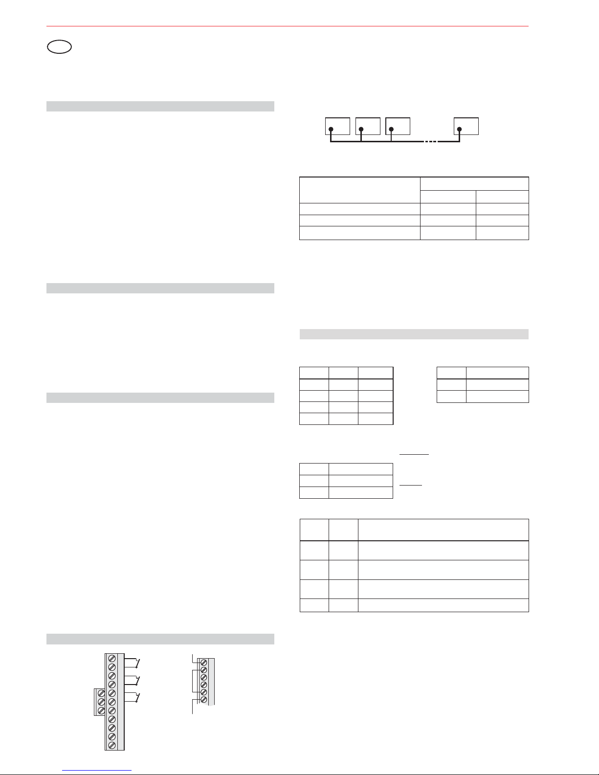
4.2 Modo de funcionamiento Easy Logic sin función FAI
Las señales de control "Test de paseo", "Desarmado" y "FAI" no están conectadas. En este
modo de funcionamiento no hay disponibles indicaciones de alarma, ni función FAI, ni
memoria.
Los interruptoresDIP S4,S5 yS6 hande estaren posición”ON”.
El sensorde microondassiempre está activo.
4.1 Modo de funcionamiento de Viewguard con función FAI
(FAI= irst larm ndication -indicación deprimera alarma)FA I
Lógica FAI:
Las salidas"F" detodos los detectoresdeben estar conectadas entresí. No es necesariauna
conexión con el panel de control. El LED parpadea en el detector que se activa primero, y
permanece fijo en los detectores activados posteriormente (véase el punto 6. "Indicación
LED").
Instrucciones de instalación
Viewguard Serie DUAL
5. Ajuste
Interruptores DIP:véase lailustración 3-
Detector 1FDetector 2 Detector 3
Detector 20
F
F
F
Función para entradas:
(Resistencias pull-up en el detector)
Función
a) Armado
b) Desarmado
c) , indicación alarma claraTest de paseo
Alto
Bajo
Entradas
Test de paseo"T"
Alto
Alto
Bajo
Bajo
No guardar:
Guardar:
La señal de fallo/enmascaramiento se borra
automáti-camente después de la eliminación del
fallo/enmascaramiento.
La señal de fallo/enmascaramiento permanece
guardada en el detector hasta que se borra mediante
el panelde control.
¡No posibleen modoEasy Logic!
Memoria:
S5 Fallo/enmascaramiento
ACT no guardar
DESACT guardar
S3 Sensibilidad
ACT normal
DESACT Alto
S1 S2 Alcance
DESACT DESACT 8 m
ACT DESACT 11 m
DESACT ACT 13 m
ACT ACT 15 m
Cerrar carcasa
Aplicar tensión de trabajo
Testde paseo enmodo Easy Logic
Véase lailust. 1en orden inverso.Asegúrese de quela carcasaestá cerradacorrectamente y
bloqueada en posición. No introduzca el sello para bloquear la carcasa hasta que no haya
finalizado lainstalación
Después de aplicar la tensión de trabajo, el detector realiza automáticamente una
inicialización.Ambos LEDs parpadean(véase 6.).
. Despuésde untiempo
máximo de 60 segundos, el detector está listo para funcionar. Después de este periodo no
cambie nadaen lasproximidades (hasta 50cm) quepueda influir sobrela luzreflejada.
El detector está en modo de test de paseo durante unos 10 minutos una vez finalizada la
inicialización. Realice el test de paseo dentro de este intervalo de tiempo. Indicación LED,
véase elpunto 6.
No introduzcael modoanti-enmascaramiento durantela inicialización
4. Diagrama de conexiones
E
Fault Tamper Alarm
Si el panel de control no tiene
ninguna entradas de fallo, las
salidas "Alarma" y "Fallo" pueden
conectarse en serie.
Fallo
Alarma
Tamper
Test de paseo
0V
+12VDC
Terminales de
repuesto para
resistencias de
final de línea
Armar/desarmar
FAI
Fault Tamper Alarm T U F
+
1. Introducción
2. Instrucciones de montaje
3. Instalación
El detector de movimiento DUAL Viewguard comprende dos sistemas que funcionan de
forma totalmente independiente: Detector pasivo de infrarrojos más detector de
microondas. El principio de funcionamiento del detector se basa en la conexión inteligente
de un sensor de infrarrojos pasivo y microondas. Este tipo de conexión hace que los
detectores sean especialmente insensibles a las turbulencias de aire y térmicas. (Módulo
de microondas, véase la ilust. 3-
.
Dispone de las siguientes características principales:
Óptica deespejo enabanico (véase lailustración. 3- , ilustración.6)
, véasela ilust.2- , (sólo 033440/450)
El sensorde microondaspuede desactivarse enel estado“desarmado”.
FAI(indicación de primeraalarma):
Cuando existen múltiples detectores en una zona única, indica el primer detector en
alarma
Alcance ysensibilidad seleccionables
Función dememoria
Alcance ysensibilidad seleccionables
Supervisión dela tensiónde funcionamiento
Autotest (sólo033440/450)
Tamper decarcasa ypared
La sensibilidad máximase alcanza cuandose monta de formacruzada respecto alas zonas
de detecciónhorizontales de lossensores PIR. Portanto, seleccione unlugar demontaje que
atraviese ladirección esperadade movimiento. (Véasela ilust.6-A).
Distancia mínimarespecto altecho: 2 cm
* Montaje porencima deradiadores
* Montaje cercade salidasde aire(p.ej., sistemasde aireacondicionado)
* Luz solardirecta
* Montaje cercade lámparasfluorescentes
* Montaje cercade bombillas
(véase la ilust. 1)
En caso necesario,rompa el sello conun pequeño destornillador uobjeto similar y tirehacia
abajo .Apriete la muesca(en el fondoen la parte central, véasela ilust.2- ) ligeramente
hacia adentro extraiga la parte frontal de la carcasa . Levante la parte frontal de la
carcasa .
• 0° vertical Ilust. 5/1 Ilust. 4-
• Vertical en un ángulo descendente de 3° Ilust. 5/2 Ilust. 4-
• Horizontal en unángulo de 45° hacia laderecha o la izquierda Ilust. 5/3 Ilust. 4-
• Montaje en esquina Ilust. 5/4 Ilust. 4El detectorpuede montarse utilizandola rótula demontaje opcional (033390ó 033588, véase
”Accesorios”).
(véase lailust. 4)
Para un cableado montado en superficie
Para un cableado montado empotrado
Para la utilización con charnela de ajuste
Para descarga de presión con brida en el cable
(véase la ilust. 4)
Necesario parala instalaciónconforme a laCLC/TS 50131-2-4Grado 3.
El tamperde paredutilizarse si seinstala comose indica enla ilust.5/1, 5/2, 5/3a,5/3b y5/4.
Empujador para tamper trasero. Quite la clavija en el empujador si se está
usando eltamper trasero(véase la ilustración)
Cubierta protectora para tamper trasero (en la parte posterior). Quitar, cuando
se montasegún lailust. 5/3a o5/4
-
-
-
-
-
-
-
-
-
-
Evite:
Abrir carcasa
Opciones de montaje Tornillo en posición
Cableado
A
B, C
C
D
Tamper de pared
a
b
Anti-enmascaramiento hastaa 30cm del detector
PIR y MW funcionan automáticamente
con el mismo alcance.
Armar/desarmar "U"
S4 S6 Modo de funcionamiento
(a )
DESACT ACT No permitido
nti-enmascaramiento sólo 033440/450
enmascaramiento
enmascaramiento
enmascaramiento
ACT ACT Modo Easy Logic sólo (véase 4.2)
ACT DESACT Modo Viewguard con FAI
DESACT DESACT ModoViewguard con FAI
Anti- siempre activo
Anti- siempre activo
Anti- inactivo en estado “armado”
 Loading...