

69-0422—03
V8200A,C,H,M and
VR8200A,C,H,M Continuous Pilot
Combination Gas Controls
INSTALLATION INSTRUCTIONS
APPLICATION
These continuous pilot combination gas controls are
used in gas-fired appliances up to 200 cfh capacity of
natural gas. They include safety shutoff, a manual valve,
one or two automatic operators, a pressure regulator and
a pilot filter. Body pattern is straight-through with 1/2 in.
inlet and 1/2 in. outlet. An ECO connector (part no.
393200-1) with two 1/4 in. quick connect terminals is
available.
See Table 1 for model differences and Table 2 for
temperature ranges and regulator types.
Additional 90° angle and straight flanges are available for
3/8, 1/2, and 3/4 in. pipe. See Table 3 for flange part
numbers. TRADELINE
with attached O-ring, four mounting screws, and a 9/64
in. hex wrench.
Model
V8200 24 V/60 Hz One OFF-PILOT-ON 0.30
VR8200 24 V/60 Hz Two OFF-PILOT-ON 0.5
Table 2. Model Number Suffix Letter Designation. Table 3. Flange Part Numbers.
Model No.
Suffix
Letter
A 0° to 175° F (-18° to 79° C) Standard
C 0° to 175° F (-18° to 79° C) Step-opening
H 0° to 175° F (-18° to 79° C) Slow-opening
M -40° to 175° F (-40° to 79° C) Standard
®
flange kits include one flange
Table 1. Continuous Pilot Combination Gas Control Models.
Vol tag e
Frequency
Ambient
Tem pera tu re
Range
Number of
Automatic Operators
Regulator
Typ e
Controls are factory-set for natural (and manufactured) or
LP gas. Do not attempt to use a control set for natural
(manufactured) gas on LP gas, or a control set for LP on
natural (manufactured) gas.
Controls with standard or slow opening regulators can be
converted from one gas to the other with a conversion kit
(order separately). Order Part No. 393691 to convert
from natural (manufactured) to LP gas; order Part No.
394588 to convert from LP to natural (manufactured)
gas. Controls with step opening regulators cannot be
converted.
CSA Certificate: 112395
Australian Gas Association Certificate: 4752
Gas Control
Knob Positions
Inlet/Outlet
Pipe Size
3/8 in. NPT Straight NA 393690-11
1/2 in. NPT Straight 393690-6 NA
3/4 in. NPT Straight 393690-4 NA
a
Elbow (angle) flanges cannot provide right hand inlet
when the ECO connector is used.
NOTE: Flange Kits include one flange with attached
O-ring and four mounting screws. TRADELINE
kits include 9/64 inch hex wrench, as noted.
Flange
Elbow
Elbow
Elbow
Typ e
a
a
a
Current
Draw
Part No.
Less
Hex
Wrench
393690-2 NA
393690-3 393690-13
393690-5 393690-15
With
Hex
Wrench
V8200A,C,H,M AND VR8200A,C,H,M CONTINUOUS PILOT COMBINATION GAS CONTROLS
WARNING
CAUTION
WARNING
INSTALLATION
When Installing This Product...
1. Read these instructions carefully. Failure to follow
them could damage the product or cause a
hazardous condition.
2. Check the ratings given in the instructions and on
the product to make sure the product is suitable for
your application.
3. Installer must be a trained, experienced service
technician.
4. After installation is complete, check out product
operation as provided in these instructions.
Fire or Explosion Hazard can cause property
damage, severe-injury or death.
Follow these warnings exactly:
1. Disconnect power supply before wiring to
prevent electrical shock or equipment damage.
2. To avoid dangerous accumulation of fuel gas,
turn off gas supply at the appliance service
valve before starting installation, and perform
Gas Leak Test after completion of installation.
3. Do not attempt to use a control set for natural
(manufactured) gas on LP gas, or a control set
for LP on natural (manufactured) gas.
4. Do not bend pilot tubing at control or pilot after
compression nut has been tightened, or gas
leakage at the connection may result.
5. Always install sediment trap in gas supply line
to prevent contamination of gas control.
6. Do not force the gas control knob. Use only
your hand to push down the reset button or turn
the gas control knob. Never use any tools. If the
knob or reset button will not operate by hand,
the control should be replaced by a qualified
service technician. Force or attempted repair
may result in fire or explosion.
Never apply a jumper across or short the valve
coil terminals. This may burn out the heat
anticipator in the thermostat.
IMPORTANT
These gas controls are shipped with protective
seals over inlet and outlet tappings. Do not
remove seals until ready to connect piping.
Follow the appliance manufacturer’s instructions if
available; otherwise, use the instructions provided below
as a guide.
Convert between Natural and LP Gas
Fire or Explosion Hazard can cause property
damage, severe-injury or death.
Do not attempt to use a control set for natural
(manufactured) gas on LP gas, or a control set
for LP on natural (manufactured) gas.
To convert a control from natural gas to LP gas, or from
LP gas to natural gas, contact your Honeywell
representative.
®
Install Adapters to Control
If adapters are to be installed on the gas control, mount
them as follows:
Flanges:
1. Choose the appropriate flanges for your application.
NOTE: A right angle inlet flange cannot be used with
ECO connected.
2. Remove seal over control inlet or outlet.
3. Check to ensure that the O-ring is fitted in the
groove of flange. If the O-ring is not attached or is
missing, do not use the flange.
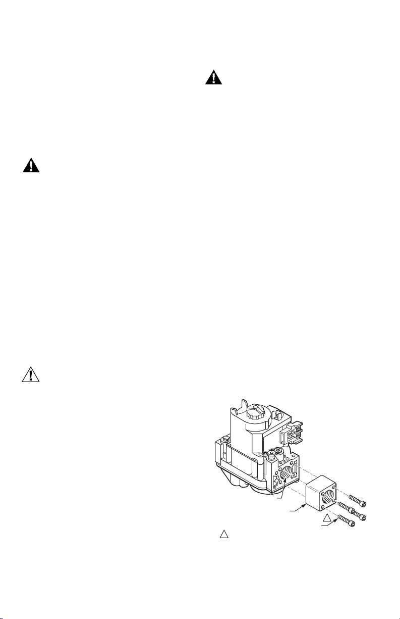
4. With O-ring facing valve, line up the screw holes on
the control with the holes in the flange. Insert and
tighten the screws provided with the flange (See
Fig. 1). Tighten the screws to 25 in.-lbs
(2.8 N·m) of torque to provide a gas-tight seal.
Bushings:
1. Remove seal over control inlet and outlet.
2. Apply moderate amount of good quality pipe
compound to bushing, leaving two end threads
bare. On LP installation, use compound resistant to
LP gas. Do NOT use Teflon™ tape.
3. Insert bushing in control and thread pipe carefully
into bushing until tight.
69-0422—03 2
GAS CONTROL OUTLET
FLANGE
1
DO NOT OVERTIGHTEN SCREWS.
TIGHTEN TO 25 INCH-POUNDS.
Fig. 1. Fasten Flange to Valve with 25 in.- lbs
9/64 INCH HEX SCREWS (4)
(2.8 N·m) Torque.
1
M2913A
V8200A,C,H,M AND VR8200A,C,H,M CONTINUOUS PILOT COMBINATION GAS CONTROLS
Complete instructions below for piping, installing control,
and connecting pilot tubing, thermocouple, and wiring.
Make certain the gas leak test you perform on the control
after completing the installation includes leak testing the
adapters and screws. If you use a wrench on the valve
after flanges are installed, use the wrench only on the
flange, not the control.
Using Adapters to Solve Swing Radius Problems
In some field service applications, it is difficult or
impossible to thread the control onto the gas supply pipe
because of space limitations. This problem can be
resolved in many instances through the use of an adapter.
The adapter is installed on the end of the supply pipe in
place of the gas control, following the same precautions
and instructions that are used for installing the gas
control. After the adapter is installed, the gas control is
attached to the adapter as outlined above. Note that use
of an adapter increases the overall length of the gas
control.
Location
Do not locate the combination gas control where adverse
environments such as steam cleaning, high humidity or
dipping water, corrosive chemicals, dust or grease
accumulation, or excessive heat are prevalent. To ensure
proper operation, follow these guidelines:
• Locate in a well ventilated area.
• Mount high enough above the cabinet bottom to avoid
exposure to flooding or splashing water.
• Ensure that the ambient temperature does not exceed
the ambient temperature ratings for each component.
• Cover if appliance is cleaned with water, steam, or
chemicals or to avoid dust and grease accumulation.
• Avoid locating where exposure to corrosive chemical
fumes or dipping water is likely.
Mount the combination gas manifold. If this is a
replacement application, mount the control in same
location as old control.
DROP
1
3 IN.
(76 MM)
MINIMUM
DROP
PIPED
GAS
SUPPLY
2
TUBING
GAS
SUPPLY
2
GAS
CONTROL
GAS
CONTROL
2
HORIZONTAL
3 IN.
(76 MM)
MINIMUM
HORIZONTAL
RISER
ALL BENDS IN METALLIC TUBING SHOULD BE SMOOTH.
1
2
CAUTION: SHUT OFF THE MAIN GAS SUPPLY BEFORE REMOVING
END CAP TO PREVENT GAS FROM FILLING THE WORK AREA. TEST
FOR GAS LEAKAGE WHEN INSTALLATION IS COMPLETE.
RISER
PIPED
GAS
SUPPLY
3 IN.
(76 MM)
MINIMUM
GAS
CONTROL
M3077A
Install Piping to Control
All piping must comply with local codes and ordinances or
with the Natural Fuel Gas Codes (ANSI Z223.1 NFPA No.
54), whichever applies. Tubing installation must comply
with approved standards and practices.
1. Use new, properly reamed pipe free from chips. If
tubing is used, make sure the ends are square,
deburred and clean. All tubing bends must be
smooth and without deformation.
2. Run pipe or tubing to the control. If tubing is used,
obtain a tube-to-pipe coupling to connect the tubing
to the control.
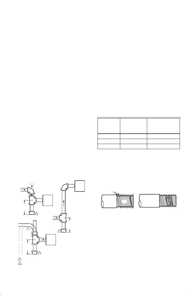
3. Install sediment trap in the supply line to the gas
control (See Fig. 2).
Install Control
1. This control can be mounted 0-90 degrees, in any
direction, from the upright position of the gas control
knob, including vertically.
2. Mount the control so gas flow is in the direction of
the arrow on the bottom of the control.
3. Thread pipe the amount shown in Table 4 for
insertion into control. DO NOT THREAD PIPE TOO
FAR. Valve distortion or malfunction may result if
the pipe is inserted too deeply.
Table 4. NPT Pipe Thread Length (in.).
Maximum Depth
Pipe
Size
Thread Pipe
this Amount
3/8 9/16 3/8
1/2 3/4 1/2
3/4 13/16 3/4
4. Apply a moderate amount of good quality pipe
compound (DO NOT use Teflon tape) to pipe only,
leaving two end threads bare. On LP installations,
use compound resistant to LP gas (See Fig. 3).
5. Remove seals over control inlet and outlet, if
necessary.
6. Connect pipe to control inlet and outlet. Use wrench
on the square ends of the control. If a flange is
used, place wrench on flange rather than control
(Refer to Fig. 4 and 5).
TWO IMPERFECT
THREADS
THREAD PIPE THE AMOUNT
SHOWN IN TABLE FOR
INSERTION INTO GAS CONTROL
GAS CONTROL
PIPE
APPLY A MODERATE AMOUNT OF
PIPE COMPOUND TO PIPE ONLY
(LEAVE TWO END THREADS BARE).
Fig. 3. Use of Moderate Amount of Pipe Compound.
Pipe can be
Inserted into
Control
M3075B
Fig. 2. Sediment Trap Installation.
3 69-0422—03
 Loading...