

Page 1
Honeywell
V400 AND V800
COMBINATION GAS CONTROLS
APPLICATION
V400 and V800 are used on gas fired standing pilot
appliances with 30 mV thermocouple. These gas controls
include a manual gas valve, safety shutoff, single millivoltage automatic operator, and pressure regulator, pilot gas
filter and flow adjustment, pressure tapping, and thermocouple connector.
V400 is used on 120V systems. V800 is used on 24V
systems. Refer to Table 1 for more specifications. Refer to
Table 2 for available gas capacities.
V800 gas controls are available with 1/4 x 1/4 inch or 3/
16 x 1/4 inch energy cut-off (ECO) quick-connects. With the
connector, an ECO high limit can be connected into the
power circuit. When the temperature at the ECO exceeds
the high limit, a switch opens and de-energizes the power
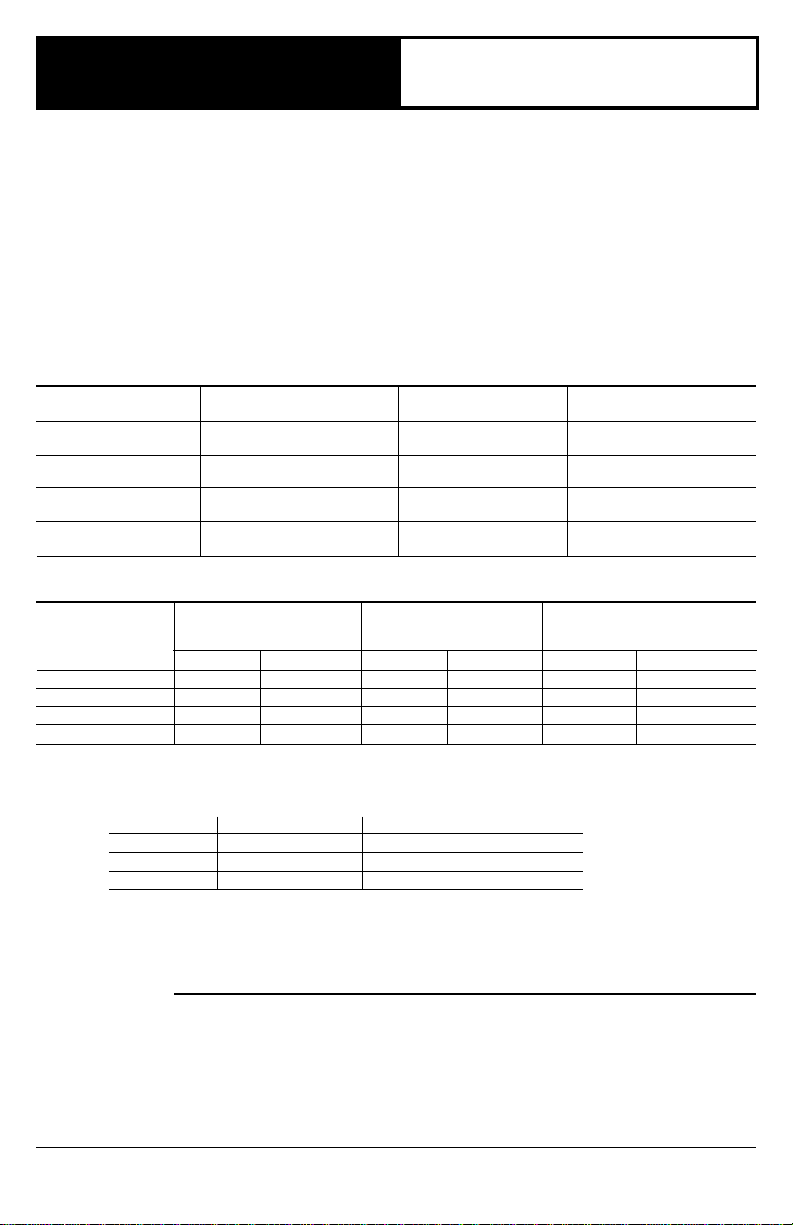
TABLE 1—MODEL SPECIFICATIONS.
MODEL NUMBER AMBIENT PRESSURE PRESSURE
SUFFIX LETTER TEMPERATURE RANGE REGULATOR TYPE REGULATOR MODEL
A32° F to 175° F Standard-Opening V5306A
C32° F to 175° F Step-Opening V5307A
M-40° F to 175° F Standard-Opening V5306B
P-40° F to 175° F Step-Opening V5307B
PIPE SIZE CAPACITY
(INLET x 1 INCH WCPD CAPACITY CAPACITY
OUTLET) ft
1/2" x 3/8" 110 3.1 110 3.1 11 0.3
1/2" x 1/2" 225 6.4 225 6.4 23 0.7
1/2" x 3/4" 250 7.1 290 8.2 23 0.7
3/4" x 3/4" 335 9.5 425 12.0 34 1.0
a
Capacity is based on 1000 Btu/ft3, 0.64 specific gravity natural gas at 1 inch wc pressure drop [37.3 MJ/m3, 0.64 specific
gravity natural gas at 0.25 kPa pressure drop]. Use conversion factors to convert to other gases.
[0° C to 79° C]
[0° C to 79° C]
[-40° C to 79° C]
[-40° C to 79° C]
TABLE 2—GAS CONTROL CAPACITIES.
GAS CONTROL MAXIMUM MINIMUM
3
/hr m3/hr ft3/hr m3/hr ft3/hr m3/hr
a
AT REGULATION REGULATION
unit and shuts off main burner and pilot gas flow. To restart
system, pilot flame must be relit and gas control must be
reset manually.
Power for the gas control and the control system is
provided by a 30 mV thermocouple. We recommend the
Q340 Thermocouple.
Replacement parts:
1. Energy cut off (ECO) connector: 392451-1
2. Pressure Regulators:
Standard opening pressure regulator: V5306A,B.
Step opening pressure regulator: V5307A,B.
3. Valve Operators:
Line Voltage Operator: V404B.
Low Voltage Operator: V804B.
TYPE OF GAS SPECIFIC GRAVITY MULTIPLY LISTED CAPACITY BY:
Manufactured 0.60 0.516
Mixed 0.70 0.765
Propane 1.53 1.62
INSTALLATION
WHEN INSTALLING THIS PRODUCT…
1. Read these instructions carefully. Failure to follow
them could damage the product or cause a hazardous
condition.
2. Check the ratings given in these instructions and on
the product to ensure the product is suitable for your
application.
J.A. Form Number 95-6996—10
Rev. 6-91 ©Honeywell Inc. 1991
3. Ensure installer is a trained, experienced service
technician.
4. After completing installation, use these instructions to
check product operation.
Page 2
WARNING
FIRE OR EXPLOSION HAZARD
CAN CAUSE PROPERTY DAMAGE, SEVERE INJURY, OR DEATH
Follow these warnings exactly:
1. Disconnect power supply before wiring to prevent
electrical shock or equipment damage.
2. To avoid dangerous accumulation of fuel gas, turn
off gas supply at appliance service valve before
starting installation and perform Gas Leak Test
following installation.
3. Do not bend pilot gas tubing at control or at pilot
burner after compression fitting is tightened. Gas
leakage at the connection may result.
4. Always install sediment trap in gas supply line to
prevent contamination of gas control.
5. Do not force gas control knob. Use only your hand
to turn gas control knob. If the knob will not operate
by hand, the control should be replaced by a
qualified service technician. Force or attempted
repair may result in fire or explosion.
Never apply a jumper across (or short) gas control
coil terminals. This may burn out thermostat heat
anticipator.
These gas controls are shipped with protective seals
over inlet and outlet tappings. Do not remove seals
until ready to connect piping.
Follow the appliance manufacturer’s instructions if available; otherwise, use the instructions provided below as a
guide.
CHOOSE LOCATION
Do not locate the combination gas control where it may
be affected by steam cleaning, high humidity, dripping
water, corrosive chemicals, dust or grease accumulation,
or excessive heat. To ensure proper operation, follow these
guidelines.
• Locate in a well ventilated area.
• Mount high enough above the cabinet bottom to
avoid exposure to flooding or splashing water.
• Ensure the ambient temperature does not exceed the
ambient temperature ratings for each component.
• Cover gas control if appliance is cleaned with water,
steam, or chemicals or to avoid dust and grease
accumulation.
• Avoid locating where exposure to corrosive chemical
fumes or dripping water are likely.
Mount combination gas control in the appliance vestibule on the gas manifold. In replacement applications,
mount gas control in the same location as the old control.
INSTALL PIPING TO CONTROL
All piping must comply with local codes and ordinances
or with National Fuel Gas Code (ANSI Z223.1 NFPA No.
54), whichever applies. Tubing installation must comply
with approved standards and practices.
1. Use new, properly reamed pipe free from chips. If
tubing is used, make sure ends are square, deburred, and
clean. All tubing bends must be smooth and without deformation.
2. Run pipe or tubing to the control. If tubing is used,
obtain a tube-to-pipe coupling to connect tubing to the
CAUTION
IMPORTANT
control.
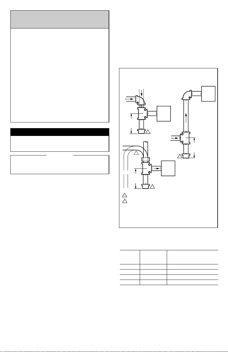
3. Install sediment trap in gas supply line. Refer to Fig. 1.
INSTALL CONTROL
1. This control can be mounted 0-90 degrees, in any
direction, from the upright position of the gas control knob,
including vertically.
2. Mount the control so gas flow is in direction of arrow
on bottom of control.
3. Thread pipe the amount shown in Table 3 for insertion
into control. DO NOT THREAD PIPE TOO FAR. Valve
distortion or malfunction may result if pipe is inserted too
deeply.
DROP
3 IN.
PIPED
GAS
SUPPLY
GAS
CONTROL
2
DROP
TUBING
1
GAS
SUPPLY
2
GAS
CONTROL
2
HORIZONTAL
3 IN.
(76 MM)
MINIMUM
HORIZONTAL
RISER
(76 MM)
MINIMUM
ALL BENDS IN METALLIC TUBING SHOULD BE SMOOTH.
1
CAUTION: SHUT OFF THE MAIN GAS SUPPLY BEFORE REMOVING
2
END CAP TO PREVENT GAS FROM FILLING THE WORK AREA. TEST
FOR GAS LEAKAGE WHEN INSTALLATION IS COMPLETE.
RISER
PIPED
GAS
SUPPLY
3 IN.
(76 MM)
MINIMUM
GAS
CONTROL
M3077
Fig. 1—Install sediment trap.
TABLE 3—NPT PIPE THREAD LENGTH (IN.).
PIPE THREAD CAN BE INSERTED
SIZE LENGTH INTO CONTROL
OVERALL MAXIMUM DEPTH PIPE
3/8 9/16 3/8
1/2 3/4 1/2
3/4 13/16 3/4
19/16 1
4. Apply moderate amount of good quality pipe compound to adapter, leaving two end threads bare. Refer to
Fig. 2. (On LP gas installations, use compound resistant to
LP gas.) Do not use Teflon tape.
5. Remove seals over control inlet and outlet, if necessary.
6. Connect pipe to control inlet and outlet. To tighten inlet
and outlet connections, use wrench on projecting wrench
boss. Refer to Figs. 3 and 4.
2
Page 3
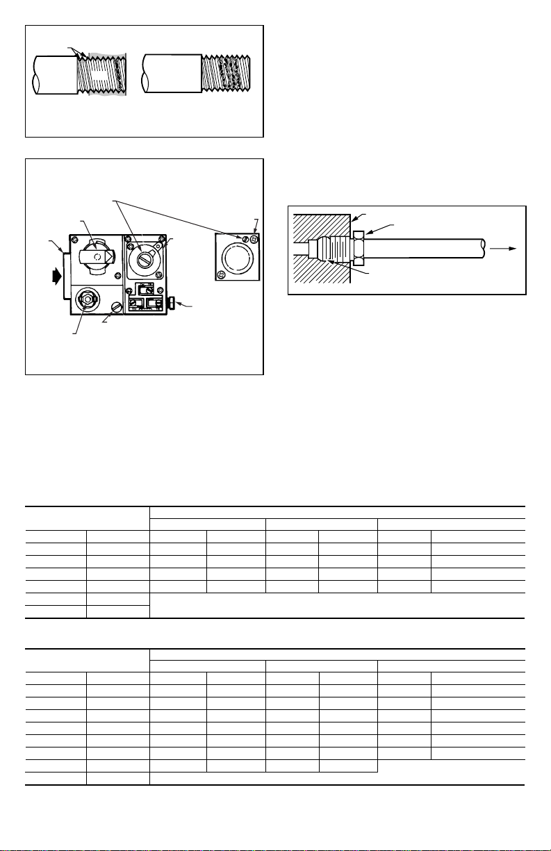
3. Unscrew brass compression fitting from pilot gas
TWO IMPERFECT
THREADS
THREAD PIPE THE AMOUNT
SHOWN IN TABLE FOR
INSERTION INTO GAS CONTROL
GAS CONTROL
PIPE
APPLY A MODERATE AMOUNT OF
PIPE COMPOUND TO PIPE ONLY
(LEAVE TWO END THREADS BARE).
M3075B
Fig. 2—Use moderate amount of pipe compound.
PRESSURE REGULATOR
ADJUSTMENT
(BENEATH COVER SCREW)
MANUAL GAS
CONTROL KNOB
WRENCH
BOSS
PILOTSTAT
POWER UNIT
GAS
INLET
OFF
INLET
PILOT
STANDARD
PRESSURE
ON
PILOT FLOW ADJ. SCREW
(BENEATH COVER SCREW)
REGULATOR
("A" MODEL)
STEP OPENING
REGULATOR ("C" MODEL)
INSTALL
LONG
SCREW IN
OUTSIDE
CORNER
PILOT GAS OUTLET.
PRESSURE TAPPING
DIRECTLY BENEATH
M17845
Fig. 3—Top view of standard capacity gas control.
CONNECT PILOT GAS TUBING
1. Cut tubing to desired length and bend as necessary
for routing to pilot burner. Do not make sharp bends or
deform tubing. Do not bend tubing at control after compression nut has been tightened, as this may result in gas
leakage at connection.
2. Square off and remove burrs from end of tubing.
outlet. Refer to Fig. 4. Slip fitting over tubing and slide out
of way.
NOTE: When replacing a control, cut off old compression
fitting and replace with new compression fitting provided
on new combination gas control. Never use old compression fitting as it may not provide a gas-tight seal.
Refer to Fig. 4.
4. Push tubing into pilot gas tapping on outlet end of the
control until it bottoms. While holding tubing all the way in,
slide fitting into place and engage threads. Turn until finger
tight. Then tighten one more turn with wrench. Do not
overtighten.
5. Connect other end of tubing to pilot burner according
to pilot burner manufacturer’s instructions.
GAS CONTROL
TIGHTEN NUT ONE TURN
BEYOND FINGER TIGHT.
FITTING BREAKS OFF AND CLINCHES
TUBING AS NUT IS TIGHTENED.
TO PILOT
BURNER
M3076A
Fig. 4—Always use new compression fitting.
CONNECT THERMOCOUPLE
The thermocouple connection to the power unit or ECO
connector (Fig. 3) is an electrical connection and must be
clean and dry. Never use pipe compound. Tighten only
1/4 turn beyond finger tight to give good electrical
continuity.
CONNECT ECO (Standard-Capacity models only)
If the ECO is provided, the leadwires must be equipped
with insulated 1/4 in. female quick-connect terminals.
Leadwire lengths must not exceed the lengths shown in
Tables 4 and 5. Connect high limit or ECO leadwires to the
two terminals on the thermocouple.
If ECO is not provided, connect a Q313B Thermopile
Generator in place of the thermocouple to act as the highlimit for the system.
TABLE 4—MAXIMUM LENGTH OF SUPPLEMENTARY LIMIT LEADWIRES WHEN USING Q340A THERMOCOUPLE.
THERMOCOUPLE MAXIMUM LEADWIRE LENGTH X 2 (wires)
LENGTH AWG NO. 14 AWG NO. 16 AWG NO. 18
in. m in. m in. m in. m
18 0.5 35 0.9 22 0.6 13 0.3
24 0.6 29 0.7 18 0.5 11 0.3
30 0.8 23 0.6 15 0.4 9 0.2
36 0.9 17 0.4 11 0.3 6 0.2
48 1.2 DO NOT USE.
60 1.5
TABLE 5—MAXIMUM LENGTH OF SUPPLEMENTARY LIMIT LEADWIRE WHEN USING Q309A THERMOCOUPLE.
THERMOCOUPLE MAXIMUM LEADWIRE LENGTH X 2 (wires)
LENGTH AWG NO. 14 AWG NO. 16 AWG NO. 18
in. m in. m in. m in. m
12 0.3 47 1.2 30 0.8 18 0.5
18 0.5 41 1.0 26 0.7 16 0.4
24 0.6 35 0.9 22 0.6 14 0.4
30 0.8 29 0.8 18 0.5 11 0.3
36 0.9 23 0.6 15 0.4 9 0.2
40 1.0 19 0.5 12 0.3 7 0.2
48 1.2 11 0.3 7 0.2
60 1.5 DO NOT USE.
3 95-6996—10
Page 4

WIRING
Follow appliance manufacturer’s wiring instructions, if
available, or use general instructions provided below.
All wiring must comply with applicable electrical codes
and ordinances or with the National Electrical Code (ANSI/
NFPA 70), whichever applies.
Disconnect power supply before making wiring connections to prevent electrical shock.
Wiring V400 models
1. Refer to Fig. 5 for typical wiring diagram.
2. Ensure power supply rating on each control matches
the available supply.
3. Install line voltage thermostat (or controller) and other
controls as required.
4. Use junction box, as shown, when connecting control
circuit to gas control operator.
5. Make conduit connection to operator as follows:
a. Slip conduit fittings over integral leadwires and
screw securely into hole in operator cover.
b. Cut flexible conduit to approximate length.
c. Slip conduit over leadwires and attach to fittings.
d. Route and connect both flexible conduits to junction box.
e. Connect integral wires to control circuit. Do not
splice except within a junction box.
STARTUP AND CHECKOUT
WARNING
FIRE OR EXPLOSION HAZARD
CAN CAUSE PROPERTY DAMAGE, SEVERE INJURY, OR DEATH
1. Do not force the gas control knob. Only use your
hand to push down and turn gas control knob.
Never use any tools.
2. If the gas control knob will not operate by hand, a
new control should be installed by a qualified
service technician.
GAS CONTROL KNOB SETTINGS
Gas control knob settings are as follows:
OFF prevents pilot and main burner gas flow.
PILOT permits pilot gas flow only. Gas control knob must
be held depressed or thermocouple must be heated sufficiently to hold the safety control valve open.
ON permits pilot or main burner gas flow under control
of thermostat and ignition module.
PERFORM GAS LEAK TEST
LINE VOLTAGE
THERMOSTAT
OR CONTROLLER
JUNCTION BOX
1
POWER SUPPLY. PROVIDE DISCONNECT MEANS AND
OVERLOAD PROTECTION AS REQUIRED.
2
LINE VOLTAGE ENCLOSURE NOT PART OF GAS CONTROL.
LINE VOLTAGE GAS CONTROLS MUST BE USED IN AN
OEM APPROVED ENCLOSURE.
2
LINE VOLTAGE
OPERATOR
LIMIT
CONTROLLER
L2
L1
(HOT)
M17846
Fig. 5—Typical V400 wiring diagram.
Wiring V800 models
1. Ensure the power supply rating on each control
matches the available supply.
2. Install transformer, low voltage thermostat, and other
controls as required.
3. Connect control circuit to operator terminals. Refer to
Fig. 6 for a typical wiring diagram.
4. Adjust thermostat heat anticipator to 0.2A rating
stamped on valve operator.
3
POWER
UNIT
24 VOLT
THERMOSTAT
POWER SUPPLY. PROVIDE DISCONNECT MEANS AND OVERLOAD
1
PROTECTION AS REQUIRED.
2
NEVER JUMPER THESE TERMINALS. THIS SHORTS OUT VALVE COIL
AND MAY BURN OUT HEAT ANTICIPATOR IN THERMOSTAT.
3
ORDER ECO LIMIT AND LEADWIRES SEPARATELY.
ECO LIMIT
ECO
CONNECTOR
CAUTION
–SEE
2
TRANSFORMER
THERMOCOUPLE
HIGH LIMIT
CONTROLLER
L1
(HOT)
L2
Fig. 6—Typical V800 wiring diagram.
M17848
WARNING
1
1
FIRE OR EXPLOSION HAZARD
CAN CAUSE PROPERTY DAMAGE, SEVERE IN-
JURY, OR DEATH
Check for gas leaks with soap and water solution any
time work is done on a gas control.
GAS LEAK TEST
1. Paint pipe connections upstream of gas control with
rich soap and water solution. Bubbles indicate gas leak.
2. If leak is detected, tighten pipe connections.
3. Stand clear while lighting main burner to prevent injury
caused from hidden leaks which could cause flashback in
the appliance vestibule. Light main burner.
4. With main burner in operation, paint pipe joints (including adapters) and control inlet and outlet with rich soap
and water solution.
5. If another leak is detected, tighten adapter screws,
joints, and pipe connections.
6. Replace part if leak can not be stopped.
LIGHT PILOT
1. Turn gas control knob clockwise to OFF. Wait
five minutes to dissipate any unburned gas. Sniff around the
appliance near the floor. Do not relight pilot flame if you
smell gas.
2. Turn gas control knob counterclockwise to
PILOT. Push down and hold the knob while lighting the pilot
flame.
3. Hold the gas control knob down about one minute,
then release.
• If pilot flame goes out, turn gas control knob
clockwise to OFF and repeat steps 1
through 3.
• If pilot flame remains lit, turn gas control knob
counterclockwise to ON.
ADJUST PILOT FLAME
The pilot flame should envelop 3/8 to 1/2 in. [10 to 13
mm] of the thermocouple tip. Refer to Fig. 7. To adjust pilot
flame:
1. Remove pilot adjustment cover screw. Refer to Fig. 3.
2. Turn inner adjustment screws clockwise to de-
4
Page 5

crease or counterclockwise to increase pilot flame.
3. Always replace cover screw after adjustment and
tighten firmly to ensure proper operation.
PROPER FLAME
ADJUSTMENT
3/8 TO 1/2 IN.
(10 TO 13 MM)
THERMOCOUPLE
M3086B
Fig. 7—Proper flame adjustment.
TURN ON MAIN BURNER
Follow appliance manufacturer instructions or adjust
thermostat to call for heat.
CHECK AND ADJUST GAS INPUT TO MAIN BURNER
CAUTION
1. Do not exceed input rating stamped on appliance
nameplate, or manufacturer’s recommended
burner orifice pressure for size orifice(s) used.
Make certain primary air supply to main burner is
properly adjusted for complete combustion. Follow appliance manufacturer instructions.
2. IF CHECKING GAS INPUT BY CLOCKING GAS
METER:
• Ensure that the only gas flow through the meter
is that of the appliance being tested.
• Ensure other appliances are turned off and
their pilot burners are extinguished (or deduct
their gas consumption from the meter reading).
• Convert flow rate to Btuh as described in the
Gas Controls Handbook (form number 70–
2602) and compare to Btuh input rating on
appliance nameplate.
3. IF CHECKING GAS INPUT WITH MANOMETER:
• Ensure gas control knob is in PILOT position
before removing outlet pressure tap plug to
connect manometer (pressure gauge).
• Turn gas control knob back to PILOT when
removing gauge and replacing plug.
• Shut off gas supply at the appliance service
valve or, for LP gas, at the gas tank before
removing outlet pressure tap plug and before
disconnecting manometer and replacing outlet
pressure tap plug.
• Perform Gas Leak Test at inlet pressure tap
plug.
V5306A,B Standard-Pressure Regulator
1. Check the manifold pressure listed on the appliance
nameplate. Gas control outlet pressure should match the
nameplate.
2. With main burner operating, check gas control flow
rate using the meter clocking method or pressure using a
manometer connected to the outlet pressure tap on the gas
control. Refer to Fig. 3.
3. If necessary, adjust pressure regulator to match appliance rating. Refer to Tables 5 and 6 for factory set nominal
outlet pressure and adjustment range.
a. Remove pressure regulator adjustment cap and
screw.
b. Using screwdriver, turn inner adjustment screw
clockwise to increase or counterclockwise
to decrease gas pressure to burner.
c. Always replace cap screw and tighten firmly to
ensure proper operation.
4. If desired outlet pressure or flow rate cannot be
achieved by adjusting the control, check the control inlet
pressure using a manometer at the inlet pressure tap. If inlet
pressure is in normal range (refer to Tables 6 and 7),
replace the control. Otherwise, take the necessary steps to
provide proper gas pressure on the control.
V5307A,B Step-Opening Pressure Regulator
1. Check the full rate manifold pressure listed on the
appliance nameplate. Gas control full rate outlet pressure
should match this rating.
2. With main burner operating, check the control flow
rate using the meter clocking method or pressure using a
manometer connected to outlet pressure tap on the control.
Refer to Fig. 3.
3. If necessary, adjust pressure regulator to match appliance rating. Refer to Tables 6 and 7 for factory set nominal
outlet pressure and adjustment range.
a. Remove pressure regulator adjustment cap screw.
b. Using a screwdriver, turn inner adjustment screw
clockwise to increase or counterclockwise
to decrease gas pressure to burner.
c. Always replace cap screw and tighten firmly to
ensure proper operation.
4. If desired outlet pressure or flow rate cannot be
achieved by adjusting the control, check the inlet pressure
using a manometer at inlet pressure tap or upstream of the
gas control. If inlet pressure is in the normal range (refer to
Tables 6 and 7), replace the existing control. Otherwise,
take the necessary steps to provide proper gas pressure to
the control.
5. Carefully check burner lightoff at step pressure. Make
sure burner lights smoothly and without flashback to orifice.
Make sure all ports remain lit. Cycle burner several times,
allowing at least 30 seconds between cycles for regulator to
resume step function. Repeat after allowing burner to cool.
Readjust full rate outlet pressure if necessary to improve
lightoff characteristics.
TABLE 6—PRESSURE REGULATOR SPECIFICATION PRESSURES IN IN. WC.
OUTLET PRESSURE
TYPE NOMINAL INLET FACTORY SETTING RANGE
NOMINAL SETTING
MODEL OF GAS PRESSURE RANGE Step Full Rate Step Full Rate
A,M NATURAL 5.0-7.0 — 3.5 — 3-5
LP 12.0-14.0 — 11.0 — 8-12
C,P NATURAL 5.0-7.0 0.9 3.5 None 3-5
LP 12.0-14.0 2.2 11.0 None 8-12
5 95-6996—10
Page 6

TABLE 7—PRESSURE REGULATOR SPECIFICATION PRESSURES IN kPa.
OUTLET PRESSURE
MODEL OF GAS PRESSURE RANGE Step Full Rate Step Full Rate
TYPE NOMINAL INLET FACTORY SETTING RANGE
A,M NATURAL 1.2-1.7 — 0.9 — 0.7-1.2
LP 2.9-3.9 — 2.7 — 2-3
C,P NATURAL 1.2-1.7 0.2 0.9 None 0.7-1.2
LP 2.9-3.9 0.5 2.7 None 2-3
NOMINAL SETTING
CHECK SAFETY SHUTDOWN PERFORMANCE
WARNING
FIRE OR EXPLOSION HAZARD
CAN CAUSE PROPERTY DAMAGE, SEVERE INJURY OR DEATH
Perform the safety shutdown test any time work is
done on a gas module.
1. Place gas control knob in PILOT position. Main burner
should go off and pilot should remain lit.
2. Extinguish pilot flame. Pilot gas flow should stop
within 2-1/2 minutes. Safety shutoff of pilot gas provides
complete shutdown since safety shutoff valve blocks flow of
gas to main burner and pilot.
3. Relight pilot burner and operate system through one
complete cycle to make sure all controls operate properly.
SERVICE
Do not apply jumper across (or short) valve coil
terminals, even temporarily. Doing so may burn out
heat anticipator in thermostat.
Allow 60 seconds after shutdown before reenergizing step-opening model to ensure lightoff at step
pressure.
IF PILOT WILL NOT LIGHT
1. Ensure the main gas supply valve is open and the pilot
gas supply line is purged of air.
2. Attempt to light pilot following procedure in “Light
Pilot”, page 4. If pilot still will not light:
a. Check pilot gas adjustment screw. If closed, read-
just pilot flame. Refer to page 4.
b. Perform gas leak test at compression fitting. If leak
is detected, replace old compression fitting or tighten new
one. Refer to page 3.
c. Ensure that pilot burner tubing or orifice is not
clogged. If clogged, replace combination gas control.
IF PILOT GOES OUT WHEN GAS CONTROL KNOB IS
RELEASED
1. Make sure the gas control knob is held in at least one
minute to allow the thermocouple time to heat.
2. Check pilot flame adjustment, refer to page 4.
3. Check the wiring between the thermocouple and the
valve operator in the gas control.
4. Ensure jumper between valve operator and power
unit is secure and connections are clean.
5. If pilot still goes out, measure the open and closed
thermocouple circuit output voltages. Compare to acceptable range charts in the thermocouple specifications or in
the Gas Controls Handbook. Replace the thermocouple if
voltages are outside the acceptable range.
CAUTION
IMPORTANT
6. Check power unit resistance. If above 11 ohms,
replace gas control.
IF MAIN BURNER WILL NOT COME ON WITH CALL
FOR HEAT
1. Make sure gas control knob is in the ON position.
2. Adjust thermostat several degrees above room tem-
perature.
3. Disconnect leadwires to lower left TH terminal and
lower right PP terminal to isolate valve operator coil from
balance of circuit. Measure resistance of coil. If coil is not 2
ohms ±10 percent, replace valve operator.
4. Measure the open and closed thermocouple output
voltages and compare to acceptable range charts in the
thermocouple specifications or in the Gas Controls Handbook. Replace the thermocouple if voltages are outside the
acceptable range.
IF BURNER IS OVERFIRING
Adjust pressure regulator to correct pressure. If regulator cannot be adjusted and supply pressure is in normal
range, replace complete gas control.
INSTRUCTIONS TO THE HOMEOWNER
WARNING
FIRE OR EXPLOSION HAZARD
CAN CAUSE PROPERTY DAMAGE, SEVERE IN-
JURY, OR DEATH
Follow these warnings exactly:
1. Pilot must be lit manually. Follow these instructions exactly.
2. Before lighting, smell around the appliance for
gas. Be sure to smell next to floor because LP gas
is heavier than air.
3. IF YOU SMELL GAS:
• Turn off gas supply at appliance service valve.
On LP gas systems, turn off gas supply at the
tank.
• Do not light any appliances in the house.
• Do not touch electrical switches or use the
phone.
• Leave the building and use a neighbor’s phone
to call your gas supplier.
• If you can not reach your gas supplier, call the
fire department.
4. Do not force the gas control knob. Use only your
hand to push down or turn the gas control knob.
Never use any tools. If the gas control knob will not
operate by hand, the gas control should be replaced by a qualified service technician. Force or
attempted repair may result in fire or explosion.
5. The gas control must be replaced in case of any
physical damage, tampering, bent terminals, missing or broken parts, stripped threads, or evidence
of exposure to heat.
6
Page 7

LIGHTING THE PILOT BURNER
STOP: READ THE WARNINGS ABOVE.
This appliance has a pilot burner which must be lit
manually. If the pilot flame has gone out, follow these
instructions exactly.
1. Set the thermostat to its lowest setting.
2. Disconnect all electric power to the appliance.
3. Remove gas control access panel.
4.Push in gas control knob slightly and turn
clockwise to OFF.
NOTE: Gas control knob can not be turned from PILOT to
OFF unless it is pushed in slightly. Do not force gas
control knob.
5. Wait five minutes to clear out any gas. If you then smell
gas, STOP! Follow “WARNING 3”. If you do not smell gas,
continue with next step.
6. Remove the pilot burner access panel located below
and behind the gas control.
7. Find the pilot burner by following the metal tube from
the gas control. The pilot is between the two burner tubes
behind the pilot burner access panel.
8. Turn gas control knob on gas control counterclockwise to PILOT.
9. Push in gas control knob all the way and hold in.
Immediately light the pilot flame with a match and continue
holding the gas control knob in for one minute after the pilot
flame is lit.
10.Release gas control knob and it will pop back up. Pilot
flame should remain lit. If pilot flame goes out, repeat steps
1 through 10.
• If gas control knob does not pop up when released,
stop and immediately and call your service technician
or gas supplier.
• If the pilot flame will not stay lit after several tries, turn
the gas control knob to OFF and call your service
technician or gas supplier.
11. Turn gas control knob counterclockwise to
ON.
12. Replace pilot burner access panel.
13. Replace gas control access panel.
14. Reconnect all electric power to the appliance.
15. Set thermostat to desired setting.
TURNING OFF THE APPLIANCE
VACATION SHUTDOWN—Set thermostat to desired room
temperature while you are away.
COMPLETE SHUTDOWN—Push in gas control knob
slightly and turn clockwise to OFF. Do not force.
Appliance will completely shut off. Follow lighting procedures above to resume normal operation.
7 95-6996—10
Page 8

U.S.A.: 1885 Douglas Drive N. Australia, Canada, Finland, France, Germany, Japan, Mexico, Netherlands,
Golden Valley, MN 55422-4386 Spain, Taiwan, United Kingdom, U.S.A.
CANADA: 740 Ellesmere Road
Scarborough, Ontario M1P 2V9 PRINTED IN U.S.A.
Honeywell Inc. International Sales Offices in all principal cities of the world. Manufacturing in
QUALITY IS KEY
 Loading...