

Honeywell V8043A1312/U, V8043A1313/U, V8043A1311/U, V8043E1412/U, V8043E1411/U Installation Instructions Manual
...
33-00402EF-01
V8043 Zone Valves
CAUTION
with Press Connection
INSTALLATION INSTRUCTIONS
Model Pipe Size Description
V8043A1311/U DN15 1/2" Zone Valve Pro Press with 18" lead wires
V8043A1312/U DN20 3/4" Zone Valve Pro Press with 18" lead wire
V8043A1313/U DN25 1" Zone Valve Pro Press with 18" lead wires
V8043E1411/U DN15 1/2" Zone Valve Pro Press with 18" lead wires and End Switch
V8043E1412/U DN20 3/4" Zone Valve Pro Press with 18" lead wires and End Switch
V8043E1413/U DN25 1" Zone Valve Pro Press with 18" lead wires and End Switch
V8043F1511/U DN15 1/2" Zone Valve Pro Press with Terminal Block Connections and End Switch
V8043F1512/U DN20 3/4" Zone Valve Pro Press with Terminal Block Connections and End Switch
V8043F1513/U DN25 1" Zone Valve Pro Press with Terminal Block Connections and End Switch
APPLICATION
These valves consist of an actuator motor and valve
assembly for controlling the flow of hot and/or cold
water. The V8043A provides two-position, straightthrough control of supply water. The valves are
designed for use with fan coil and other units
requiring quiet, compact water valves. The V8043E
and V8043F also control supply water for baseboard
radiators and convectors.
INSTALLATION
When Installing this Product...
1. Read these instructions carefully. Failure to
follow them could damage the product or cause
a hazardous condition.
2. Check the ratings given in the instructions and
on the product to make sure the product is
suitable for your application.
3. Installer must be a trained, experienced service
technician.
4. After installation is complete, check out product
operation as provided in these instructions.
1. Disconnect power supply before connecting
wiring to prevent electrical shock of
equipment damage.
2. Normally it is not necessary to remove the
powerhead from the valve body during
installation. If the valve must be disassembled,
be certain that it is reassembled with the water
flow in the direction of the arrow. Reversal of
the powerhead will result in damage to the
gear train.
3. On 24V systems, never jumper the valve coil
terminals even temporarily. This may burn
out the heat anticipator in the thermostat.
IMPORTANT
Use this valve in hydronic heating systems
which do not contain dissolved oxygen in the
system water. The dissolved oxygen, which is
found in systems that have a frequent source
of m akeu p wa ter, c ause s the rubb er pl ug i nsid e
the valve to deteriorate and eventually fail.
LOCATION
Install the valve in an area with adequate clearance to:
— move the manual opening lever on the side of
the powerhead;
— remove the powerhead cover;
— wire the powerhead;
— replace the powerhead motor.
The valve location should be in an area where the
temperature does not exceed the maximum valve
operating temperature as shown in Specifications.
V8043 ZONE VALVES WITH PRESS CONNECTION
M37333
3–7/16
(88)
X
7/8
(23)
2–11/32
(59)
3–3/32
(79)
5–1/4
(133)
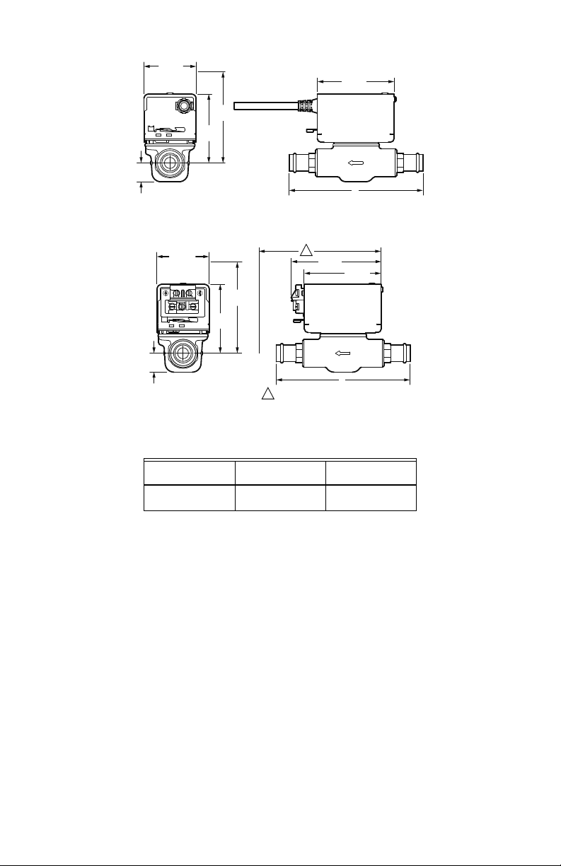
Fig. 1. Dimensions (V8043A, V8043E). Measurements in inches (mm). See Table 1.
2–11/32
(59)
END SWITCH
TH TR
TH TR
7/8
(23)
3–3/32
(79)
5–1/4
(133)
Fig. 2. Dimensions (V8043F). Measurements in inches (mm). See Table 1.
Table 1. X dimension. See Fig. 1 or Fig. 2.
1/2 in. Valves
DN15
6–13/32 in.
163 mm
SPECIFICATIONS
Static Pressure Rating:120 psi
Maximum Differential Pressure
and Capacity Ratings (C
1/2 in. valves at 20 psi: C
3/4 in. valves at 20 psi: C
1in. valves at 6.5psi: C
Temperature Rating:
Liquid: 4 to 93 °C (40 to 200 °F).
Ambient: 4 to 52 °C (40 to 125 °F).
Steam: Consult your local Honeywell representative.
Humidity Rating: 5-95% RH (non-condensing)
Atmosphere: non-corrosive, non-explosive
):
v
v
v
v
= 3
= 3
= 8.5
1
4–1/16
(103)
3–7/16
(88)
X
1
ALLOW ADEQUATE CLEARANCE TO
ACCESS WIRING TERMINALS.
3/4 in. Valves
DN20
6–25/32 in.
173 mm
Power Requirements and Timing:
All models: 24 V, 50/60 Hz (cycles) 6 W nominal,
15 seconds to open, and 4-5 seconds to close.
Order transformer separately.
Tran sform er:
All models: AT72 or AT20B (maximum of 4 valves per
AT72 or 2 valves per AT20B).
Order transformers separately.
Auxiliary Switch Ratings:
‘E’, ‘F’ Models: 4.4 Amps running at 120 Vac.
Recommended Wall Thermostats:
Heating Only - T86A, T822D:
(T822C for normally open [N.O.] valves).
Cooling Only, or Heating-Cooling - T87F with Q539.
Thermostat Heater Setting:
For heat anticipation: 0.32 Amps.
1in. Valves
DN25
6–7/8 in.
175 mm
M37334
33-00402EF—01 2
V8043 ZONE VALVES WITH PRESS CONNECTION
WARNING
M10162A
VERTICAL
PIPING
HORIZONTAL
PIPING
MOUNTING
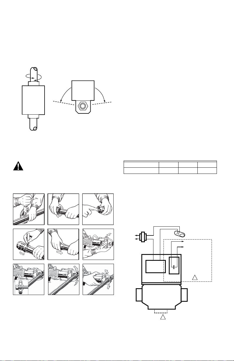
The valve can be mounted in any position on a vertical
line. If the valve is mounted horizontally; the
powerhead must be even with or above the center line
of the piping. Make sure that enough room is provided
above the powerhead to remove the cover for
servicing.
Fig. 3. Mounting positions.
Mount the valve directly in the tube or pipe. Make sure
that the flow through the valve is in the direction
indicated by the arrow stamped on the valve body.
Read and understand all instructions for
installing the press connection. Failure to
follow all instructions may result in extensive
property damage, serious injury or death.
123
3. Check seal for correct fit. Do not use oils or
lubricants.
4. Mark proper insertion depth as shown in Table 2.
Improper insertion depth may result in improper
seal.
5. While turning slightly, slide press fitting onto
tubing to the marked depth.
NOTE: End of tubing must contact stop.
6. Insert appropriate jaw into the pressing tool and
push in, holding pin until it locks in place.
7. Open the jaw and place at right angles on the
fitting. Visually check insertion depth using
mark on tubing.
8. Start the pressing process and hold the trigger
until the jaw has engaged the fitting.
9. After pressing, the jaw can be opened again.
10. Leak Testing with Smart Connect®:
Unpressed connections are located by
pressurizing the system with air or water. When
testing with water the proper pressure range is
15 psi to 85 psi maximum. Leak testing with air
can be dangerous at high pressures. When
testing with compressed air the proper pressure
range is ½ psi to 45 psi maximum. Following a
successful leak test, the system may be pressure
tested up to 200 psi with air, or up to 600 psi with
water, if required by local code requirements or
project specifications.
Table 2. Insertion depth.
Tube Size 1/2 in. 3/4 in. 1 in.
Insertion Depth 3/4in. 7/8in. 7/8in.
WIRING
Disconnect the power supply before connecting wiring
to prevent electrical shock or equipment damage.
All wiring must comply with local codes and
ordinances. Connections to the individual valves are
shown in Fig. 5-6.
45 6
78
Reproduced with permission from Viega LLC (2018).
1. Cut copper tubing at right angles using
2. Remove burr from inside and outside of tubing
Fig. 4. Mounting procedure.
displacement-type cutter or fine-toothed steel
saw.
to prevent cutting sealing element.
M37346
9
TO
LINE
YELLOW
LEADS
MOTOR
AUXILIARY
SWITCH
1 NOT APPLICABLE FOR V8043A.
THERMOSTAT
(TYPICALLY T87F)
TO CIRCULATOR
OR ANOTHER VALVE
RED LEADS
1
M37335
Fig. 5. Typical wiring for V8043A, V8043E.
3 33-00402EF—01
 Loading...