

Page 1
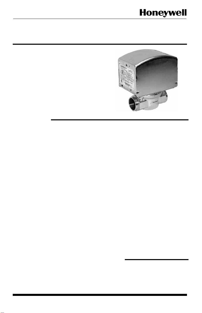
V8043A,E,F 5000 Series
APPLICATION
These valves consist of a motorized
actuator and valve assembly for controlling
the flow of hot water to a heat exchanger
such as a radiator, convector, finned
baseboard radiator, or infloor radiant coil
for space temperature control. The V8043
5000 series valves provide two-position,
straight through control of supply water at
up to 300 psi operating pressure.
Quick Fit actuator provides easy snap on and
off connection to the valve assembly.
SPECIFICATION
ZONE V ALVES
Patent Pending
Actuator Electrical Rating:
24Vac 60 Hz, 0.30 A Current Draw,
5 W, 7.2 VA maximum
Electrical Connection:
18” leads or screw terminal board
Auxiliary Switch Rating:
120V, 4.4A running, 26.4A Inrush (60 Hz);
50 VA Pilot duty at 24 V.
Fluid Temperature:
Standard models (class F motor):
200° F (93° C) Max.
Ambient Temperature:
125° F (52° C) Max.
Humidity Limits:
95% Relative Humidity, Non-condensing
Shipping and Storage Temperature:
-40° F to 150° F (-40° C to 65° C).
Atmosphere:
Non-corrosive, non explosive.
Maximum Soldering Temperature:
500° F (260° C). Rubber ball plug must be
moved away from the seat for soldering.
Maximum System Pressure Rating:
300 psi (2000 kPa), PN20.
Flow Characteristics:
Quick opening for on-off application.
Slow return for water hammer resist.
Maximum Close-off Rating (@ Flow
Capacity Rating) :
20 psi (@ 3.5 Cv)
8 psi (@ 8 Cv)
Actuator Materials:
Case:galvanized steel.
Cover : zinc plated steel.
Sector gear: Brass
Valve Material:
Body of forged brass; drive shaft stem of
stainless steel; ball plug of Buna-N rubber;
o-ring seals of EPDM rubber.
Service Medium:
Suitable for glycol/water mix up to 50:50
use in closed hydronic systems. Not for
use with oxygenated water, potable water
or steam.
Use this valve in hydronic systems which
do not contain dissolved oxygen in the
system water. The dissolved oxygen,
which is found in systems that have a
frequent source of make-up water, causes
the rubber plug inside the valve to
deteriorate and eventually fail.
Approvals:
CSA C/US Certified to Canadian Standards
Association and Underwriter's Laboratories
Standards.
MODELS
V8043 (Straight through, Normally Closed)
V8043A: Leadwires
V8043E: Leadwires and End Switch
V8043F: Terminal Board and End Switch
2004.09 Printed in Canada
1
Form No. 95C-10932
Page 2
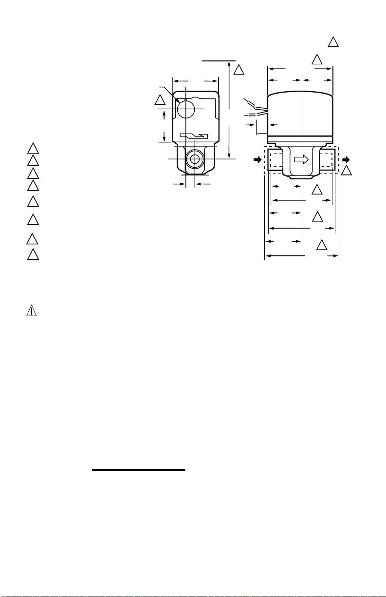
1
HEIGHT NEEDED TO REMOVE COVER.
2
DIMENSIONS FOR 1/2 IN. COPPER TUBING.
DIMENSIONS FOR 3/4 IN COPPER TUBING.
3
DIMENSIONS FOR 1 IN. COPPER TUBING.
4
4-7/8 IN. (124) MAX ON V8034F WITH TERMINAL
5
BOARD ENCLOSURE.
V4034B AND V8043B VAL VES THAT ARE
6
NORMALLY OPEN IN THE DE-ENERGIZED
POSITION HAVE NO MANUAL LEVER.
REFER TO MOUNTING INSTRUCTIONS.
7
OPENING FOR 1/2 IN. CONDUIT ON MANUAL
8
LEVER SIDE FOR V4043, V8043.
Fig. 1 - Mounting Dimensions in in. (mm in Brackets)
M10175.A4
V4043, V8043 SWEAT COPPER CONNECTION MODELS
3-1/2 (89)
1-3/4
(44)
A B
1-5/16
(33)
1-3/8
(35)
1-11/16
(43)
7/8 DIA.
(22)
8
1-1/2
(38)
15/32
(12)
AUTO
2-3/8
(60)
MAN OPEN
5-1/4
(133)
1
3/8
(10)
IN
1-3/4
(44)
2-5/8
(66)
2-3/4
(70)
3-3/8
(86)
6
5
OUT
7
2
3
4
CAUTION
1. Disconnect power supply before
connecting wiring to prevent electrical
shock or equipment damage.
2. Normally it is not necessary to remove
the actuator from the valve body during
installation. If the valve must be
disassembled, be certain that it is
reassembled with the water flow in the
direction of the arrow. Reversal of the
actuator results in damage to the gear
train.
3.
On 24V systems, never jumper the
valve coil terminals even tempor arily.
This can burn out the heat anticipator in
the thermostat.
INSTALLATION
When Installing this Product…
1. Read these instructions carefully. Failure
to follow them could damage the product
or cause a hazardous condition.
2. Check the ratings given in the
instructions and on the product to make
sure the product is suitable for your
application.
3. Installer must be a trained, experienced
service technician.
4. After installation is complete, check out
product operation as provided in these
instructions.
Location
Install the valve in an area with adequate
clearance to:
- Move the manual opening lever on the
side of the actuator
- Remove the actuator cover
- Wire the actuator
Replace the actuator motor
-
The valve location should be in an area
where the temperature does not exceed the
maximum valve operating ambient
temperature and fluid temperatuare.
Manual Lever
The V8043 normally closed valves can be
opened manually by moving the manual lever
slowly and firmly to the MAN. OPEN position
and pushing up to the stop. The stop permits
the valve to be locked in the open position.
The valve returns to automatic position when
it is energized.
2
Page 3
R
L1
(HOT)
L2
1
1
POWER SUPPLY. PROVIDE DISCONNECT MEANS AND
OVERLOAD PROTECTION AS REQUIRED.
END SWITCH
TO CIRCULATOR
OR ANOTHER
VALVE
TH
TR
24V
TRANSFORMER
THERMOSTAT
(TYPICALLY T87F)
TH TR
M5952
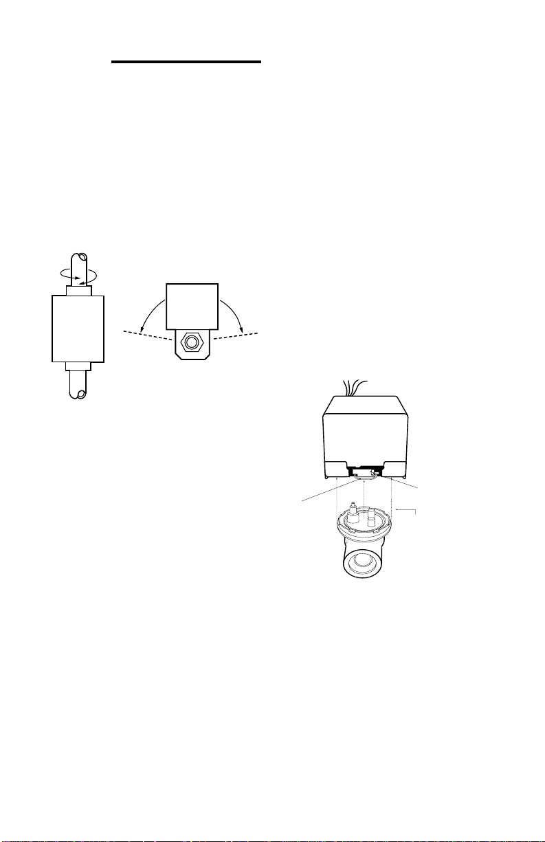
MOUNTING
The valve can be mounted in any position
on a vertical line. See Fig. 2. If the valve is
mounted horizontally; the actuator must be
even with or above the center line of the
piping. Make sure to leave enough room
above the actuator to remove the cover for
servicing.
thermostat or controller connected to the
valve so that the valve runs through its
cycle. Make sure the valve runs
smoothly and positively from closed to
open to closed again. (See Operation
and Checkout Sections.)
Mount the valve directly in the tube or pipe
after the coil.
Make sure that the flow
through the valve is in the direction
indicated by the arrow stamped on the
valve body.
HORIZONTIAL
PIPING
VERTICAL
PIPING
Fig. 2 - Mounting Positions
M10162
Sweat Copper Models
1. Use new, properly reamed pipe, free
from dents or corrosion.
2. Place the valve on the pipe. Set the
manual opening lever to MAN. OPEN
position before applying heat. This
protects the plug inside the valve by
removing it from the seat.
3. Sweat the joints, keeping the outer
surface free from solder. DO NOT use
silver solder because of the high
melting temperature required.
TO INSTALL A COMPLETE VALVE (V8043):
1. Disconnect power supply before
connecting wiring to prevent electrical
shock or equipment damage.
2. Install valve into pipe on the return side
of the coil. (See Mounting Section.)
3. Make wiring connections to valve. (Refer
to Wiring section for proper instructions.)
4. Inspect the valve installation to ensure
that all connections and adjustments
have been correctly made.
Adjust the
TO REMOVE THE ACTUATOR FROM THE
VALVE BODY (See Fig. 3)
NOTE!
It is not necessary to drain the hydronic
system if the valve body assembly remains in
the pipe line.
1. Switch power supply OFF. Disconnect
electrical leads carefully, noting the
position and colour of each lead.
2. Place the manual lever in the MAN.
OPEN position.
3. Remove actuator by fully depressing
spring release button and lift it straight
off of the body .
1. PLACE MANUAL
AUTO OPEN
2. DEPRESS
LOCKING
BUTTON
Fig. 3 - Removing Actuator from Valve Body
LEVER IN OPEN
POSITION
3. LIFT ACTUATOR
STRAIGHT UP
TO INSTALL REPLACEMENT ACTUATOR
ON THE VAL VE BODY
1.
Align the parallel flat surfaces in
double-D shaft of valve body with
notch in side of body (i.e. 90
flow.) See Fig. 4.
This makes actuator
to water
°
attachment easier.
2. Wiring connections may be made either
before or after actuator installed on
valve body.
3.
Place the manual lever on the
actuator in the MAN. OPEN position.
3
Page 4

4. Line up motor coupling to the parallel flat
R
L1
(HOT)
L2
1
1
POWER SUPPLY. PROVIDE DISCONNECT MEANS AND
OVERLOAD PROTECTION AS REQUIRED.
END SWITCH
TO CIRCULATOR
OR ANOTHER
VALVE
TH
TR
24V
TRANSFORMER
THERMOSTAT
(TYPICALLY T87F)
TH TR
M5952
surfaces in double-D shaft of body and fit
the actuator onto the valve body,
ensuring that the shaft seats correctly .
(See Fig. 5)
5. Snap actuator onto body by pressing
down.
6.The manual lever may be released
manually, but it is also automatically
released when the valve is operated
electrically.
Double-D
Shaft
Notch
Actuator
Coupling
Fig. 4 - Shaft Position
Parallel flat surfaces
align with Notch on
side of valve body
Notch Tab
TO (TYPICALLY T87F)
LINE
YELLOW
LEADS
MOTOR
AUXILIARY
SWITCH
Fig. 6 - Typical wiring for V8043E, V8044E.
THERMOSTAT
TO CIRCULATOR
OR ANOTHER VALVE
RED LEADS
M5953
Fig. 5 - Installing Actuator
WIRING
Disconnect the power supply before
connecting wiring to prevent electrical shock
or equipment damage.
All wiring must comply with local codes and
ordinances. Connections to the individual
valves are shown in Fig. 6 and 7. See Fig. 8
through 14 for typical hookups.
If replacing a Taco, Dole, Flair or White
Rodgers 3-wire valve with a 2-wire V8043E or
F, see Fig. 15 through 27. Check that the
pressure rating of the new valve is
appropriate for the application.
Notch
Fig. 7 - Typical wiring for V8043F.
T822 T822 T822
L1
(HOT)
L2
1
POWER SUPPLY. PROVIDE DISCONNECT MEANS AND OVERLOAD
1
PROTECTION AS REQUIRED.
2
CONNECT V8043A BLACK LEADWIRE TO THERMOSTAT.
2 2 2
V8043A V8043A V8043A
M10168
Fig. 8 - T822 Thermostat, V8043A valve hookup.
4
Page 5

T822 T822 T822
T822 T822 T822
L1
(HOT)
L2
1
POWER SUPPLY. PROVIDE DISCONNECT MEANS AND OVERLOAD
1
PROTECTION AS REQUIRED.
2
CONNECT V8043E YELLOW LEADWIRE TO THERMOSTAT.
CONNECT V8043E RED LEADWIRES TO L1 (HOT) LINE AND
3
PRIMARY CONTROL.
Fig. 9 - T822, V8043E zone hookup for gas or oil. No domestic hot
2 2 2
V8043E V8043E V8043E
3 3 3
L4006A
TO OIL PRIMARY
CONTROL OR TO
TRANSFORMER
AND LOW VOLTAGE
GAS VALVE
CIRCULATOR
water.
HIGH
LIMIT
M10169
L1
(HOT)
L2
1
POWER SUPPLY. PROVIDE DISCONNECT MEANS AND OVERLOAD
1
PROTECTION AS REQUIRED.
2
CONNECT V8043E YELLOW LEADWIRE TO THERMOSTAT.
CONNECT V8043E RED LEADWIRES TO AQUASTAT®.
3
Fig. 10 - T822, V8043E zone hookup for gas or oil with or ithout
domestic hot water. Without domestic hot water, use L8148J for
gas, and L8148A for oil. With domestic hot water, use L8124E for
gas, and L8124A or C for oil.
2 2 2
V8043E V8043E V8043E
3 3 3
T T
1
2 C1
CIRCULATOR
B1
TO BURNER
CONTROL
CIRCUIT
B2
C2
M10170
V4044, V8044
VALVE OPERATOR
1
MOTOR
AQUASTAT® CHANGEOVER CONTROL SWITCHES TO HEATING (RED)
1
AT FLUID TEMPERATURE OF 85°F (29°C) MAX TO COOLING (BLUE) AT
FLUID TEMPERATURE OF 60°F (18°C) MIN.
Fig. 11 - Wiring diagram for V4244 and V8244 with Aquastat®
changeover control.
RED
BLUE
YELLOW
HEATING
COOLING
THERMOSTAT
TO
POWER
M10171
ZONE 1
ZONE 2 ZONE 3
T87F
V8043F
END SWITCH
TH-TR
TH
TR
TV
C1
TO
CIRCULATOR
Fig. 12 - Typical 3-zone system. Use an AT87A Transformer
to power up to five more zone valves.
V8043F V8043F
END SWITCH END SWITCH
TH-TR
TH
TR
2
1
B1
B2
TO BURNER
CIRCUIT
L1
(HOT)
L2
T Z
L8124G
C2
5
T87F
TH-TR
TH
120 V
POWER
SUPPLY
T87F
ADD
JUMPER
TO EACH
VALVE
TR
M5954
Page 6

ZONE 1
ZONE V8043E
RED
RED
RED
RED
YELLOW
YELLOW
W775A PANEL
T87F
CONNECTIONS FOR V8043E
(LEADWIRE MODEL)
ZONE 3
END SWITCH
V8043F
TH-TR TH
ZONE 3
YELLOW
POWER
SUPPLY
YELLOW
B
B
R
W
BR
L1
(HOT)
L2
TO
CIRCULATOR
CONTROL
CIRCUIT
ZONE 1
END SWITCH
V8043F
TH-TR TH
ZONE 1
INTEGRAL
TRANSFORMER
W775A PANEL
T87F
ZONE 2
END SWITCH
V8043F
TH-TR TH
TR
B
B
R
W
BR
TR
ZONE 2
B
B
R
W
BR
T87F
Fig. 13 - Typical 4-zone system. Use an additional W775A to power up to four more zone valves.
ZONE 2
T87F T87F T87F T87F
ZONE 3
ZONE 4
T87F
ZONE 4
END SWITCH
V8043F
TH-TR TH
TR
B
B
R
W
BR
ZONE 5
ZONE 4
TR
B
B
R
W
BR
T87F
M5980
TO BURNER
AND / OR
CIRCULATOR
CIRCUIT
V8043F
END SWITCH
TH-TR
TH
TR
NOTE: IF CODE PERMITS, V8043E AND V8043F CAN BE USED INTERCHANGEABLY WHEN WIRED AS SHOWN.
V8043F
END SWITCH
TH-TR
TH
TR
AT87A
TRANSFORMER
V8043F
END SWITCH
TH-TR
L1
(HOT)
L2
1
TH
TR
Fig. 14 - Typical 5-zone system. Use an AT87A Transformer to power up to five more zone valves.
1
L1
(HOT)
L2
POWER SUPPLY. PROVIDE DISCONNECT MEANS
1
AND OVERLOAD PROTECTION AS REQUIRED.
THERMOSTAT
A
TO AUXILIARY
CIRCUITS
B
C
Fig. 15 - Existing Taco system. (Wires are identified with
letters to correspond with wires in Fig. 16 and 17.)
D
E
TACO VALVE
1
2
3
M5958
L1
(HOT)
L2
POWER SUPPLY. PROVIDE DISCONNECT MEANS
1
AND OVERLOAD PROTECTION AS REQUIRED.
Fig. 16 - Wiring Honeywell V8043E to Taco System (Wires are
identified with letters to correspond with wires in Fig. 15.)
6
V8043E V8043E
YELLOW
YELLOW
RED
RED
POWER SUPPLY. PROVIDE DISCONNECT MEANS AND
1
OVERLOAD PROTECTION AS REQUIRED.
1
C
A
THERMOSTAT
TO
AUXILIARY
CIRCUITS
B
D
E
YELLOW
YELLOW
RED
RED
M10164
V8043E
YELLOW
YELLOW
RED
RED
M10163
Page 7

L1
(HOT)
L2
V8043F
END SWITCH
1
C
TH-TR
TH
A
D
TO
AUXILIARY
E
CIRCUITS
L1
(HOT)
L2
1
TR
B
A
B
C
V8043F
END SWITCH
TH-TR
TH
F
TO TERMINALS
E
T, T ON
BURNER RELAY
TR
D
THERMOSTAT
V8043F
L1
(HOT)
L2
END SWITCH
1
C
TH-TR
A
TH
D
TO
AUXILIARY
E
CIRCUITS
TR
B
THERMOSTAT
1
POWER SUPPLY. PROVIDE DISCONNECT MEANS AND
OVERLOAD PROTECTION AS REQUIRED.
Fig. 17 - Wiring Honeywell V8043F to Taco System (two options).
(Wires are identified with letters to correspond with wires in Fig. 15.)
DOLE VALVE
B
A
C
THERMOSTAT
1
L1
(HOT)
L2
POWER SUPPLY. PROVIDE DISCONNECT MEANS
1
AND OVERLOAD PROTECTION AS REQUIRED.
3
D
1
M5960
2
4
E
F
TO TERMINALS
T, T ON
BURNER RELAY
M5977
Fig. 18 - Existing Dole System. (Wires are identified with letters to
correspond with wires in Fig. 19 and 20.)
V8043E
YELLOW
YELLOW
RED
RED
M5965
C
B
THERMOSTAT
A
E
F
1
L1
(HOT)
L2
TO TERMINALS
T, T ON
BURNER RELAY
POWER SUPPLY. PROVIDE DISCONNECT MEANS
1
AND OVERLOAD PROTECTION AS REQUIRED.
D
Fig. 19 - Wiring Honeywell V8043E to Dole System. (Wires are
identified with letters to correspond with wires in Fig. 18.)
THERMOSTAT
V8043F
END SWITCH
1
L1
(HOT)
L2
1
Fig.20 -. Wiring Honeywell V8043F to Dole System (two options).
(Wires are identified with letters to correspond with wires in Fig. 18.)
A
B
TH-TR
C
THERMOSTAT
POWER SUPPLY. PROVIDE DISCONNECT MEANS AND
OVERLOAD PROTECTION AS REQUIRED.
F
TO TERMINALS
E
T, T ON
BURNER RELAY
TH
TR
D
M5966
FLAIR VALVE
E
L1
(HOT)
L2
1
3
A
2
1
B
4
5
C
F
D
TO TERMINALS
T, T ON
BURNER RELAY
THERMOSTAT
1
POWER SUPPLY. PROVIDE DISCONNECT MEANS AND
OVERLOAD PROTECTION AS REQUIRED.
Fig. 21 - Existing Flair System. (Wires are identified with
letters to correspond with wires in Fig. 22 and 23.)
C
B
THERMOSTAT
A
D
E
F
1
L1
(HOT)
L2
TO TERMINALS
T, T ON
BURNER RELAY
POWER SUPPLY. PROVIDE DISCONNECT MEANS
1
AND OVERLOAD PROTECTION AS REQUIRED.
Fig. 22 - Wiring Honeywell V8043F to Flair System. (Wires are
identified with letters to correspond with wires in Fig. 21.)
M5978
V8043E
YELLOW
YELLOW
RED
RED
M5965
7
Page 8

V8043F
L1
(HOT)
L2
END SWITCH
1
A
B
TH-TR
C
F
TO TERMINALS
E
T, T ON
BURNER RELAY
TH
TR
D
THERMOSTAT
V8043F
L1
(HOT)
L2
END SWITCH
1
A
B
TH-TR
C
F
TO TERMINALS
E
T, T ON
BURNER RELAY
TH
TR
D
THERMOSTAT
1
POWER SUPPLY. PROVIDE DISCONNECT MEANS AND
OVERLOAD PROTECTION AS REQUIRED.
Fig. 23 - Wiring Honeywell V8043F to Flair System (two options).
(Wires are identified with lettersto correspond with wires in Fig. 21.)
WHITE-RODGERS
WATER VALVE
THERMOSTAT
5 6
4
1
POWER SUPPLY. PROVIDE DISCONNECT MEANS AND OVERLOAD
PROTECTION AS REQUIRED.
1311 OR 1321
VALVE
5
TO AUXILIARY
CIRCUIT
3 4 6
2
1
Fig. 24 - Existing White-Rodgers System.
1
L1
(HOT)
L2
5
6
3
TO
AUXILIARY
CIRCUIT
1
L1
(HOT)
L2
1
POWER SUPPLY. PROVIDE DISCONNECT MEANS AND
OVERLOAD PROTECTION AS REQUIRED.
2
IF TRANSFORMER SUPPLIES POWER TO AUXILIARY CIRCUIT,
WIRE AUXILIARY CIRCUIT AS SHOWN IN LOWER DIAGRAM.
3
TAPE UNUSED END AND TUCK INTO HOLE.
4
THERMOSTAT
TO 6 ON
THERMOSTAT
TO AUXILIARY
CIRCUIT
Fig. 25 - Wiring Honeywell V8243E to White-Rodgers System.
YELLOW
YELLOW
RED
RED
YELLOW
RED
RED
M5966
1
L1
(HOT)
L2
M5711
2
M5712
V8043F
END SWITCH
TH
TH-TR
6
5
4
3
1
2
L1
(HOT)
L2
TO AUXILIARY
CIRCUITS
THERMOSTAT
TO
AUXILIARY
CIRCUIT
END SWITCH
TH-TR
TH-TR
3
THERMOSTAT
TH
END SWITCH
5
TO AUXILIARY
2
CIRCUITS
L1
(HOT)
1
L2
1
POWER SUPPLY. PROVIDE DISCONNECT MEANS AND
OVERLOAD PROTECTION AS REQUIRED.
2
IF TRANSFORMER SUPPLIES POWER TO AUXILIARY CIRCUIT,
WIRE AUXILIARY CIRCUIT AS SHOWN IN LOWER DIAGRAM.
3
TAPE UNUSED END AND TUCK INTO HOLE.
Fig. 26 - Wiring Honeywell V8043F to White-Rodgers System
(one option).
2
L1
(HOT)
1
L2
TO
AUXILIARY
2
CIRCUIT
L1
(HOT)
1
L2
POWER SUPPLY. PROVIDE DISCONNECT MEANS AND
1
OVERLOAD PROTECTION AS REQUIRED.
IF TRANSFORMER SUPPLIES POWER TO AUXILIARY CIRCUIT,
2
WIRE AUXILIARY CIRCUIT AS SHOWN IN LOWER DIAGRAM.
TAPE UNUSED END AND TUCK INTO HOLE.
3
Fig. 27 - Wiring Honeywell V8043F to White-Rodgers System
(alternate option).
8
TR
TR
M5713
V8043F
TH TR
6
4
END SWITCH
M5714
Page 9

OPERATION
CAUTION
On 24V systems, never jumper the valve
coil terminals even temporarily. This can
burn out the heat anticipator in the
thermostat.
Automatic Operation
On a call for heat by the zone thermostat,
the valve opens and its auxiliary switch
contacts make, closing the circuit to the
system circulator. In a multizone system with
all the valve auxiliary switches wired in
parallel, any zone calling for heat can operate
the circulator. When the call for heat ends, the
valve closes by integral spring return. The
auxiliary switch contacts break the circulator
circuit.
Manual Operation
The motorized valve can be opened
manually by lifting the manual opening lever
over the stop and pushing slowly and firmly to
the MAN. OPEN position. The stop permits
the valve to be lock ed in the open position.
The valve returns to automatic position when
the valve is energized.
Normally Closed Models
With the manual opener set to AUTO and
the actuator energized, the valve is opened
as shown in Fig. 28A. When the actuator is
de-energized, a spring-return mechanism
drives the valve to the closed position as
shown in Fig. 28B. The valve can also be
opened with no electrical power by moving
the manual opening lever over the stop and
pushing slowly and firmly to the MAN. OPEN
position. The stop permits the valve to be
locked in the open position.
The valve returns to the automatic position
when the valve is energized.
Auxiliary switch is not energized when
the valve is manually opened.
NOTE: Flow direction arrow is stamped on
the valve body indicating flow
direction from Inlet Port A to Outlet
Port B.
B
AA
IN OUT
OPEN POSITION
A
Fig. 28 - V8043 operation for normally closed valve.
OUT
IN
CLOSED POSITION
B
M5951
CHECKOUT
1. Raise the setpoint on the zone
thermostat above the room
temperature to initiate a call for heat.
2. Observe all control devices—the valve
should open and the auxiliary switch
should make the circuit to the
circulator or other valve at the end of
the opening stroke.
3. Lower the setpoint on the zone
thermostat to below the room
temperature.
4. Observe the control devices. The valve
should close and the auxiliary
equipment should stop.
SERVICE
This valve should be serviced by a trained,
experienced service technician.
1. If the valve is leaking, drain the system
and check to see if the O-ring needs
replacing.
2. If the gear train is damaged, replace
the entire actuator assembly. See the
Installation section. If the motor is
burned out, replace the motor. See
Replacement Parts list in the
TRADELINE® Catalog.
NOTE: Honeywell zone valves are designed
and tested for silent operation in
properly designed and installed
systems; how ever , water noises can
occur as a result of excessive water
velocity or piping noises can occur in
high temperature (higher than 212° F
(100° C) systems with insufficient water
pressure. Valves are designed for
normal cycling operations. Product life
will be shortened if energized
continuously.
B
9
Page 10

Automation & Control
Honeywell
1985 Douglas Drive North
Golden Valley
MN 55422-3992
In Canada
Honeywell Limited/Limitée
35 Dynamic Drive
Toronto, Ontario
M1V 4Z9
10
 Loading...