

Page 1
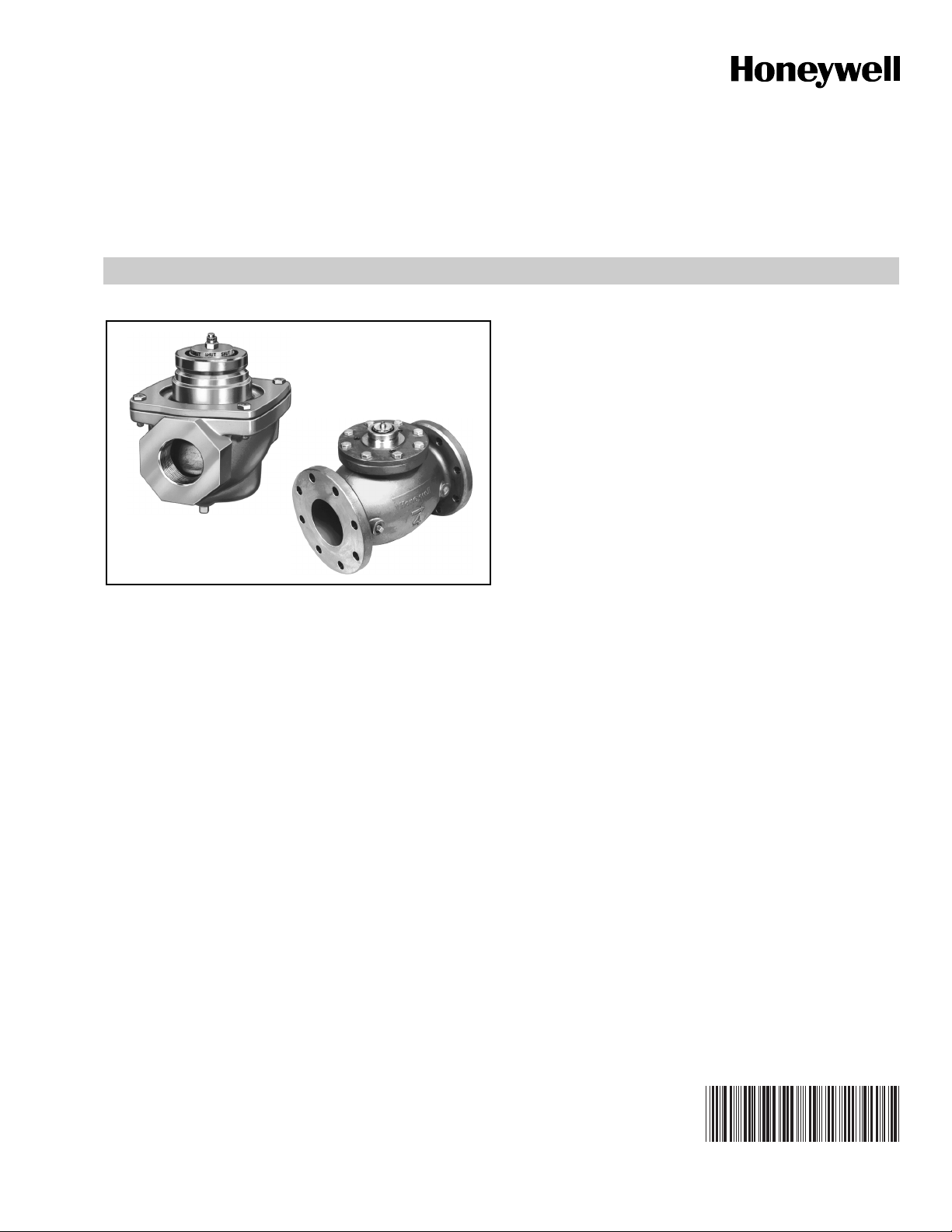
V5055A-F
Industrial Gas Valves
APPLICATION
The V5055 Gas Valves are used with the V4055, V4062,
and V9055 Fluid Power Actuators to control gas flow to
commercial and industrial burners.
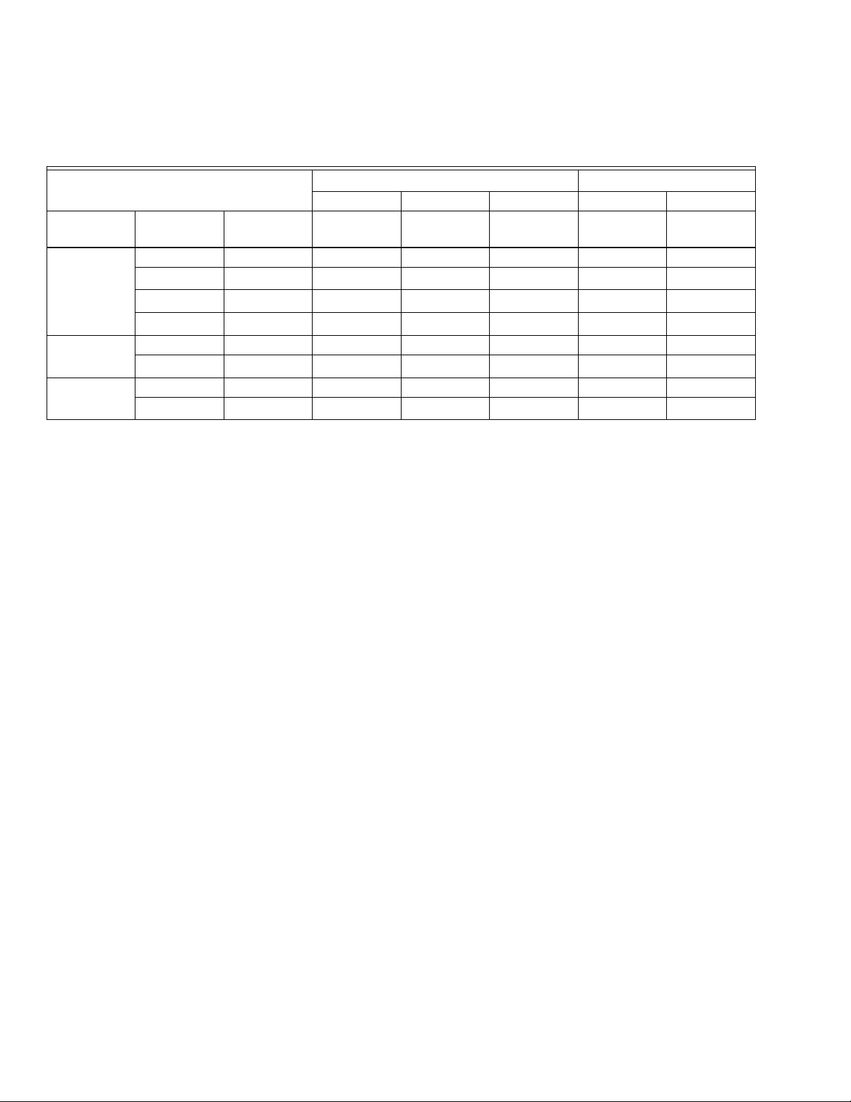
While it is possible to combine any V5055 gas valve with any
V4055, V4062, V9055 fluid actuator, a limited range of
combinations apply to the applications most often used. See
Table 1.
PRODUCT DATA
FEATURES
• Used with natural or liquefied petroleum (LP) gases.
• V5055 normally closed valves are rated for final shutoff
service (safety shutoff).
• V5055A,C,D,E Valves are for On-Off service.
• V5055B Valve has a characterized guide and in
combination with the V4055, V4062, and V9055 Fluid
Power Actuators, provides slow-opening, hi-lo-off,
and modulating functions respectively.
• V5055C,E,F Valves have a double seal and are used
with V4055D,E Actuators to provide proof-of-closure
switch and valve seal overtravel interlock.
• V5055D,E,F Valves are for high pressure applications
(see Table 2).
• Seven valve sizes from 3/4 to 3 inches have NPT
threaded connections. Models are available with
BSP-PL threads. V5055A,B,C Valves are available
in a 4 inch size and have flange connections.
• Most models have 1/4 inch upstream and downstream
tap and plug. BSP-PL thread models have 1/4 inch
upstream tap and plug.
• Valve body rating of 75 psi (5.2 bar).
• Yellow SHUT indicator attached to the valve stem
provides an indication of the valve closed position.
• Unpainted, die-cast aluminum body.
Contents
Application ........................................................................ 1
Features ........................................................................... 1
Specifications ................................................................... 2
Ordering Information ........................................................ 2
Gas Valve Sizing .............................................................. 5
To Size Two Identical Valves Piped In Series ................... 5
Installation ........................................................................ 7
Operation and Checkout .................................................. 8
Service Information .......................................................... 10
60-2307-16
Page 2
V5055A-F INDUSTRIAL GAS VALVES
SPECIFICATIONS
Table 1. Usual Combinations of Fluid Power Actuators and V5055 Industrial Gas Valves.
Fluid Power Actuators/
Industrial Gas Valves
V5055A V5055B V5055C V5055D V5055E
Pressure
Type Model
V4055
On-Off
V4062
Hi-Lo-Off
V9055
Modulating
a
Refer to Table 2 or actual pressure ratings of the various combinations of valves and actuators.
b
Valve guide has notches to determine valve flow characteristics guide; provides a more linear relationship between stem travel
A Low • • •
B High
c
D
c
E
, F
Low • •
High
A Low •
c
D
Low • •
A Low •
c
D
Low
Rating
a
On-Off
d
•
Low pressure
Characterized
Guide
•
a
b
d
VSOI
d
•
e
•
c
High Pressure
On-Off VSOI
d
•
and gas flow.
c
Valve seal overtravel interlock. Valve has two seals, and actuator has a proof-of-closure switch.
d
These combinations have higher pressure ratings; see Table 2.
e
Verify flow curve requirements to application requirements.
a
c
d
•
e
•
ORDERING INFORMATION
When purchasing replacement and modernization products from your TRADELINE® wholesaler or distributor, refer to the
TRADELINE® Catalog or price sheets for complete ordering number.
If you have additional questions, need further information, or would like to comment on our products or services, please write or
phone:
1. Your local Honeywell Automation and Control Products Sales Office (check white pages of your phone directory).
2. Honeywell Customer Care
1885 Douglas Drive North
Minneapolis, Minnesota 55422-4386
In Canada—Honeywell Limited/Honeywell Limitée, 35 Dynamic Drive, Toronto, Ontario M1V 4Z9.
International Sales and Service Offices in all principal cities of the world. Manufacturing in Australia, Canada, Finland, France,
Germany, Japan, Mexico, Netherlands, Spain, Taiwan, United Kingdom, U.S.A.
60-2307—16 2
Page 3

V5055A-F INDUSTRIAL GAS VALVES
Table 2. V5055 Models.
Model
Standard Pressure Valves
V5055A,B,C
High Pressure Valves
V5055D,E,F
d
Standard Pressure Actuators
V4055A,D, V4062 V9055
Pipe Size
(in. NPT)
a
MOPD
psi mbar psi mbar psi bar psi bar psi bar psi bar
MOP
b
MCOP
c
3/4 to 2 5 340 15 1000 15 1 15 1 15 1 15 1
2 to 3 13 880
3/4 to 2 5 340 40 2700 75 5 25 1.6 62 4 75 5
2 to 3 13 880 45 3 15 1 21 1.4 45 3
High Pressure Actuators
V4055B,E, V4062B
a
MOPD
MOP
b
MCOP
V5055A,B,C 4 3 207 7 483 15 1 5 340 mbar 12 827 mbar 15 1
a
Maximum operating pressure differential. Once open, the valve and actuator operate correctly against this pressure at 85% of
rated voltage.
b
Maximum opening pressure. Actuator opens valve against this pressure at 85% of rated voltage.
c
Maximum close-off pressure. Maximum allowable pressure drop across fully closed valve prevents seal leakage (independent of
75 psi valve body rating).
d
V5055F available in 1 in., 1-1/2 in., and 2-in. sizes only.
c
Models: See Table 3.
Table 3. Industrial Gas Valve Models.
Model Number Features
V5055A Industrial Gas Valve for On-Off service.
V5055B Industrial Gas Valve with characterized
guide for slow opening, HI-LO-OFF, or
modulating service.
V5055C Same as V5055A but incorporates a double
seal. Used with the V4055D Actuator to a
provide proof-of-closure switch and a valve
seal overtravel interlock.
V5055D Same as V5055A but for high pressure
applications.
V5055E Same as V5055C but for high pressure
applications.
V5055F Same as V5055E but meets the intent of
EN161 leakage requirements.
Type of Gas: Natural or liquefied petroleum (LP) only.
Pipe Size: 3/4, 1, 1-1/4, 1-1/2, 2, 2-1/2, 3, and 4 in.
(only V5055A,B,C available in 4 in. size).
Pipe Threads: NPT or BSP-PL Threads (equivalent to ISO
R7 and DIN 2999). Available on inlet and outlet of 3/4 to 3 inch
valves. Four inch valves have flange connections.
Pressure Ratings: See Table 2.
Valve Body Rating: 75 psi (5.2 bar).
Valve Capacities: At 1 in. (2.5 mbar) pressure drop; based on
gas with specific gravity of 0.64.
Upstream Tapping and Plug: 1 /4 in. NPT or BSP-PL
is standard.
Downstream Tapping and Plug:
1/4 in. NPT on most domestic models.
1/8 in. NPT on V5055C1182.
Ambient Operating Temperature Rating:
-40°F to 150°F (-40°C to 66°C); -40°F to 125°F
(-40°C to 52°C) when used with V9055.
Table 4. Valve Rated Capacity.
CSA Rated Capacity
Valve Size (in.)
3/4 665 18.8
1 960 27.2
1-1/4 1406 39.8
1-1/2 1717 48.6
2 3620 102.5
2-1/2 4250 120.3
3 5230 148.1
4 (V5055A) 10200 288.8
4 (V5055B,C) 9180 259.9
cf/h cu m/hr
Material: Die-cast aluminum.
Mounting: Mounts directly in the gas supply line.
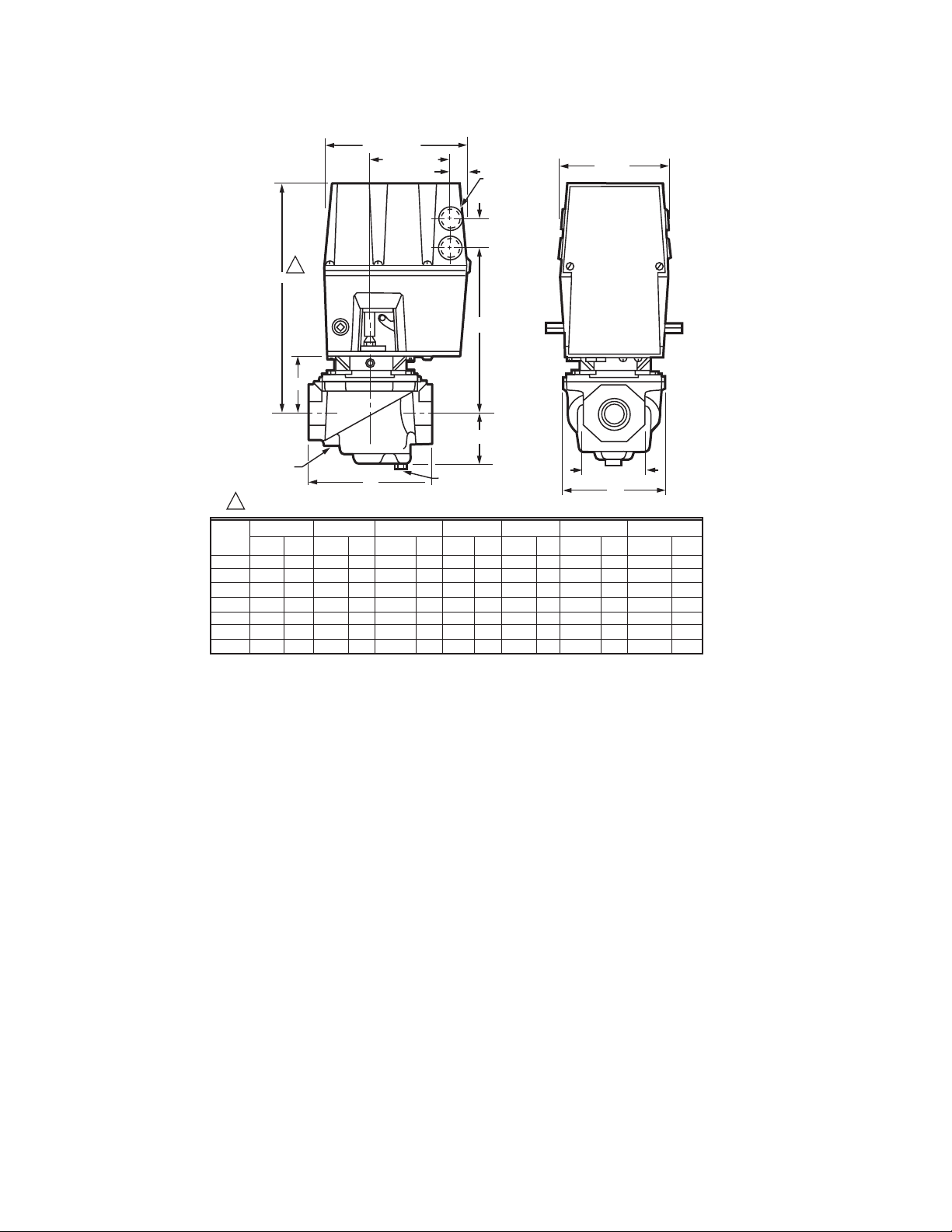
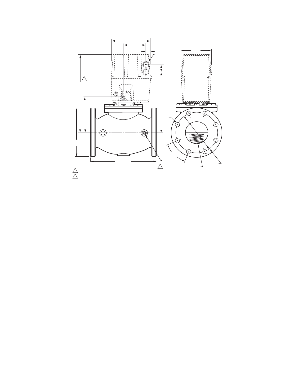
Dimensions: See Fig. 2 and 3.
Weight:
3/4, 1, 1-1/4, 1-1/2, in. valve: 4 lb. (1.8 kg).
2 in. valve: 8 lb. (3.6 kg).
2-1/2, 3 in. valve: 11 lb. (5.0 kg).
4 in. valve: 28 lb. (12.7 kg).
3 60-2307—16
Page 4
V5055A-F INDUSTRIAL GAS VALVES
1234567891234567891234567891
1
100.0
9
(250)
8
7
6
5
4
3
100.0
9
8
7
6
5
4
3
2
10.0
1
(25)
9
8
7
6
5
4
3
[1 in. wc = 2.5 mbar]
2
PRESSURE DROP, INCHES WC
11.0
(2.5)
.9
.8
.7
.6
.5
.4
.3
.2
3/4 INCH
1 INCH
1 INCH
1 1/4 INCH
1 1/2 INCH
2 INCH
2 1/2 INCH
3 INCH
4 INCH V5055B, C
4 INCH V5055A
1.0
1.0
.9
.8
.7
.6
.5
.4
.3
.2
2
9
8
7
6
5
4
3
2
.1
100
(2.8)
CAPACITY, IN CUBIC FEET PER HOUR (cf/h) FOR GAS WITH SPECIFIC GRAVITY OF 0.64 [1 cf/h = 0.0283 cu m/hr]
1000
(28)
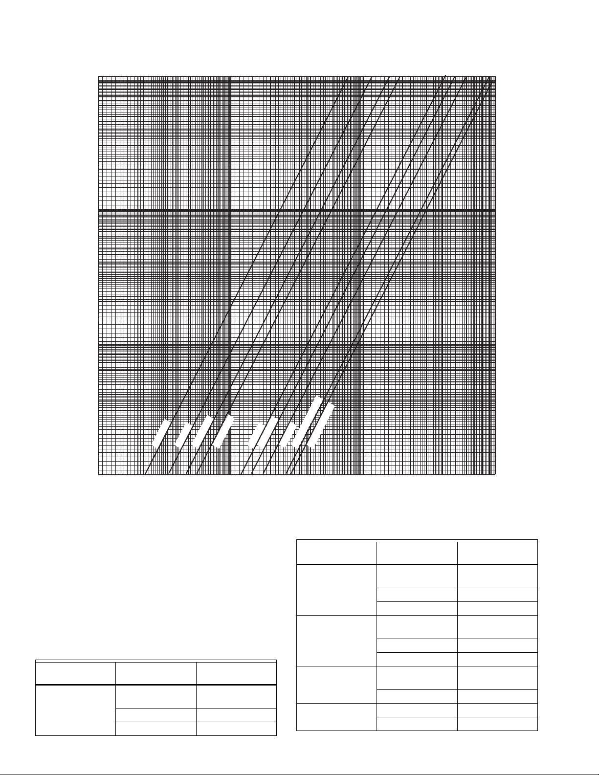
Fig. 1. Flow curves for V5055 Valves.
Replacement Parts:
Replacement Seal Assembly: Includes valve seal, bonnet seal,
and tube of lubricant.
133393A: for 3/4, 1, 1-1/4, and 1-1/2 in. valves
133392A: for 2, 2-1/2, and 3 in. valves.
137253A: for 4 in. valves.
Replacement Bonnet Assembly: Includes complete bonnet
assembly, plus the required replacement seal assembly.
See Table 5.
Table 5. Replacement Bonnet Assemblies.
Replacement
Valve Model Valve Size (in.)
V5055A
(On-Off)
3/4, 1, 1-1/4,
1-1/2
Bonnet Assembly
133398AA
2, 2-1/2, 3 133417AA
4 136911AA
60-2307—16 4
10,000
(283)
100,000
(2830)
M9542A
.1
Table 5. Replacement Bonnet Assemblies. (Continued)
Replacement
Valve Model Valve Size (in.)
V5055B
(Characterized
guide)
3/4, 1, 1-1/4,
1-1/2
2, 2-1/2, 3 133417BA
Bonnet Assembly
133398BA
4 136911BA
V5055C
(Valve-closed
indicator)
3/4, 1, 1-1/4,
1-1/2
2, 2-1/2, 3 133417CA
133398CA
4 136911CA
V5055D
(High pressure
On-Off)
V5055E (Valve
Closed Indicator)
3/4, 1, 1-1/4,
136308AA
1-1/2
2, 2-1/2, 3 136307AA
3/4, 1, 1-1/4, 1-1/2 136308BA
2, 2-1/2, 3 136307BA
Page 5
V5055A-F INDUSTRIAL GAS VALVES
Approvals:
The following combinations of V5055 Valves (3/4 through 4 in.)
and V4055, V4062 and V9055 Fluid Power Actuators are
approved by these agencies:
Underwriters Laboratories Inc. Listed: (File No. MH1639,
Guide No. YIOZ):
V4055A,B,D,E/V5055A,B,C,D,E,F
V4062/V5055A,B,C,E,F
V9055/V5055A,B,C,E,F
Swiss Re (Formerly GeGap/IRI) Acceptable:
V4055A,B,D,E/V5055A,B,C,D,E,F
V4062/V5055A,B,C,E,F
V9055/V5055A,B,C,E,F
Factory Mutual Approved (Report No. ID9AZ.AF).
CSA File No. 158158-1205788:
V4055A/V5055A,B V4055E/V5055E
V4055B/V5055D V4062/V5055B,C
V4055D/V5055C V9055/V5055B,C
NOTE: CSA does not certify models equipped with
BSP threads.
British Gas Corporation and Dutch Gas Institute Approved:
V4055 or V4062 with V5055A1145, A1152, A1160,
A1178, B1168, B1184, B1192, B1200, B1218.
Australian Gas Association Approved:
V5055B1267, B1275, and B1291.
DIN-DVGW Approved (Germany):
V5055A1145, A1152, A1160, A1178, B1168, B1184, B1192,
B1200, and B1218.
3. Find the capacity in cf/h. If the capacity is listed in
Btu/h, convert to cfh by the following formula:
Capacity in cf/h = :Btu/h (from burner nameplate)
Btu/cu ft (from gas utility)
4. For gases with specific gravities other than 0.64, multiply
the burner cfh by the proper conversion factor. See Table
6.
Table 6. Gas Conversion Factors.
Type of Gas sp gr (average) Multiply cf/h by:
Manufactured 0.60 0.968
Mixed 0.70 1.046
Propane 1.53 1.546
Butane 1.98 1.759
5. Use the corrected burner capacity in cf/h when
determining the gas valve size in Fig. 1.
6. Determine the maximum pressure drop across the valve
and draw a horizontal line at this pressure in Fig. 1.
7. Draw a vertical line in Fig. 1 at the capacity (cf/h)
previously determined. Use the corrected capacity for
a gas with a specific gravity other than 0.64.
8. Use the valve size at the intersection of the horizontal
and vertical lines. If the intersection is between valve
sizes, use the next higher size to the right.
GAS VALVE SIZING
1. Check the burner nameplate for (a) the type of gas used,
and (b) the gas flow capacity. The capacity will
be listed in Btu/h (Btus per hour) or in cf/h (cubic foot per
hour).
2. Call the gas utility for information on (a) the specific gravity (sp gr) and (b) Btu per cubic foot (Btu/cu ft) for type of
gas used.
TO SIZE TWO IDENTICAL VALVES PIPED IN SERIES
1. Find the cf/h for the type of gas used.
2. Consider both valves as one unit. Determine the total
maximum pressure drop across the unit.
3. Find the pressure drop across the first valve by
assuming it to be 45 percent of the total pressure drop.
4. Find the valve size from Fig. 1.
5. The second valve will be the same size as the first valve.
5 60-2307—16
Page 6
V5055A-F INDUSTRIAL GAS VALVES
A
6-3/4 (172)
3-23/32 (95)
27/32 (21)
1
KNOCKOUT
FOR1/2 INCH
CONDUIT (4)
1-9/32
(33)
5 (127)
C
B
1/4 INCH NPT
DOWNSTREAM
TAP AND PLUG
D
1
ALLOW 2 IN. (51 mm) CLEARANCE FOR ACTUATOR REMOVAL.
VALV E
SIZE
INCH
3/4
1
1-1/4
1-1/2
2
2-1/2
3
DIM A
IN. MM
11-1/8
11-1/8
11-1/8
11-1/8
11-1/4
11-3/4
11-3/4
283
283
283
283
286
299
299
DIM B
IN. MM
2-3/4
2-3/4
2-3/4
2-3/4
2-7/8
3-3/8
3-3/8
70
70
70
70
73
86
86
DIM C
IN. MM
8-3/16
8-3/16
8-3/16
8-3/16
8-5/16
8-13/16
8-13/16
208
208
208
208
211
224
224
E
1/4 INCH NPT UPSTREAM
TAP AND PLUG
DIM D
IN. MM
5-3/4
5-3/4
5-3/4
5-3/4
8-3/8
9-1/4
9-1/4
146
146
146
146
213
235
235
DIM E
IN. MM
2-1/4
2-1/4
2-1/4
2-1/4
2-3/4
2-3/4
2-3/4
57
57
57
57
70
70
70
DIM F
IN. MM
4-7/8
4-7/8
4-7/8
4-7/8
7-19/32
7-19/32
7-19/32
OCTAGON
F
124
124
124
124
193
193
193
OCTAGON
IN. MM
2-13/16
2-13/16
2-13/16
2-13/16
3-1/2
4-1/2
4-1/2
71
71
71
71
89
114
114
M27268
Fig. 2. Approximate dimensions of the 3/4 through 3 in. V5055 Valves, with valve actuator, in in. (mm).
60-2307—16 6
Page 7
V5055A-F INDUSTRIAL GAS VALVES
(171.5)
6-3/4
3-23/32
(94.5)
(21.4)
27/32
1
14-5/32
(360)
5-25/32
(147)
9-5/32
(233)
12-1/2 (318)
1
ALLOW 2 IN. (51 mm) CLEARANCE ABOVE V4055 SO IT MAY BE REMOVED FROM VALVE.
2
DIMENSIONS ON DIN-APPROVED VALVES: 1/4 - 19 BSP.PL UPSTREAM PLUG (2),
.71 IN (18 mm) DIAMETER BOLT HOLE (16), 7.087 IN (180 mm) DIAMETER BOLT CIRCLE.
KNOCKOUT
FOR1/2 INCH
CONDUIT (4)
1-9/32
(33)
11-7/32
(285)
3/4 (19)
DIAMETER
(16)
1/4 - 18 NPT
UPSTREAM
PLUG (2)
2
45 (16)
5 (127)
4 (102)
DIAMETER
7-1/2 (191)
DIAMETER
M9584
Fig. 3. Approximate dimensions of the 4 in. V5055 Valves, with valve actuator, in in. (mm).
INSTALLATION
IMPORTANT:
The V5055 Valve is designed to provide control
of gaseous fuel (natural and LP gas) flow in
applications in which there is minimal exposure to
water. V5055 Valves used in maritime, beverage,
food processing, outdoor and other installations in
which occasional exposure to water is experienced
may be subject to valve stem and spring corrosion.
The presence of corrosion decreases the operating
life of the valve. V5055 Valves used in such
installations should be inspected at least annually and
should have the valve bonnets replaced if corrosion is
noted.
A V4055 Valve Actuator with a NEMA 4 rating is also
recommended for such installations. The water-tight
design of the NEMA 4 rated V4055 Actuator prevents
water from entering the V4055 valve stem and spring
chamber through the actuator. Under certain
conditions, some water may be retained by the
external upper portion of the valve body. The retained
water is effectively excluded from the valve stem and
spring chamber by a functional seal that is
incorporated into the NEMA 4 rated actuator.
When Installing This Product…
1. Read these instructions carefully. Failure to follow
them could damage the product or cause a hazardous
condition.
2. Check the ratings given in the instructions and on the
product to make sure the product is suitable for your
application.
3. Installer must be a trained, experienced, flame
safeguard control technician.
4. After installation is complete, check out product
operations as provided in these instructions.
7 60-2307—16
Page 8
V5055A-F INDUSTRIAL GAS VALVES
WARNING
Electrical Shock Hazard and Explosion Hazard.
Can cause serious injury, death or property
damage.
1. Turn off gas supply before starting installation.
2. Disconnect power supply for valve actuator before
beginning installation to prevent electrical shock and
equipment damage.
3. Be sure the valve is installed so the arrow on
the valve points in the direction of gas flow.
(Gas pressure helps to close the valve.)
Location
Install the valve in the gas supply line downstream from the
pressure regulator. The valve and actuator may be mounted in
any position that allows sufficient clearance for installation and
for repair or replacement.
1. The valve position indicators should be easily visible with
the valve and actuator in the final position.
2. The final position of the valve and actuator must allow for
damper linkage, if used.
IMPORTANT:
Allow room for turning the valve body (actuator not
attached) onto the gas piping. Swing dimensions,
measured from the center of the pipe are:
3/4 through 1-1/2 in. valves: 4 in. (101.6 mm).
2 through 3 in. valves: 5 in. (127.0 mm).
4 in. valves: 7 in. (177.8 mm).
Mounting (Figs. 4 through 6)
WARNING
Explosion Hazard.
Can cause serious injury, death or property
damage.
If flow is not in the direction of the arrow on the valve
body, the valve may not shut off.
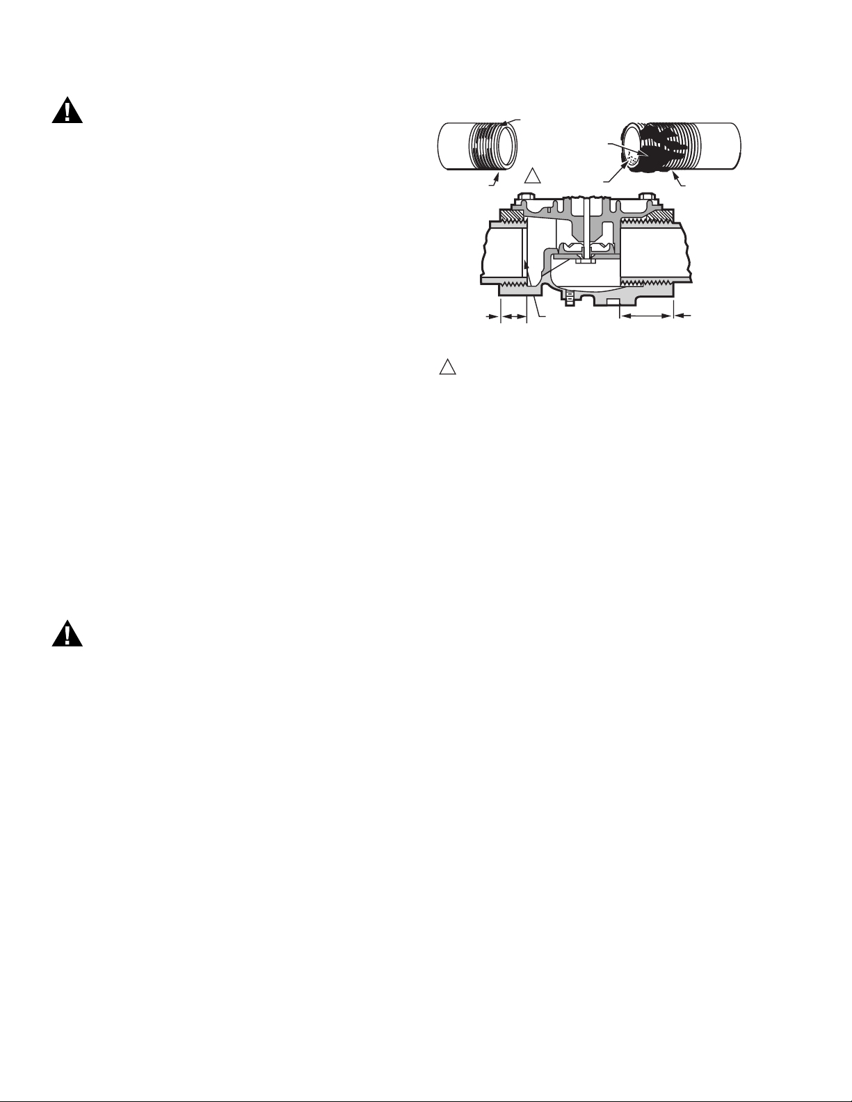
1. Use new, properly reamed, pipe, free from chips.
2. Do not thread pipe too far (Fig. 4). Valve distortion or
malfunction may result from excess pipe in the valve.
TWO CLEAN
THREADS,
MODERATE
AMOUNT
OF DOPE
CORRECT:
NORMAL
FULL
THREAD
CORRECT:
NORMAL
FULL
THREAD
11USE PIPE DOPE RESISTANT TO ACTION OF LP GAS.
EXCESS DOPE MAY BLOCK
DISK OFF
VALVE
SEAT
LOOSE
CHIPS
REAM PIPE,
BLOW OUT
CHIPS (TO AVOID
LODGING ON SEAT)
INCORRECT:
TOO LONG,
DISTORTS
VALVE SEAT
INCORRECT:
TOO LONG,
DISTORTS
VALVE SEAT
M9571
Fig. 4. Preparing the pipes.
3. Remove the protective caps from the ends of the valve.
Do not attach the valve actuator until the valve body
installation is complete.
4. Apply good quality pipe dope resistant to action of
LP gas, putting a moderate amount on the male threads
only. Use dope sparingly; if pipe dope lodges on the
valve seat, it will prevent proper closure.
5. Install valve with the gas flow in the direction indicated by
the arrow on the casting.
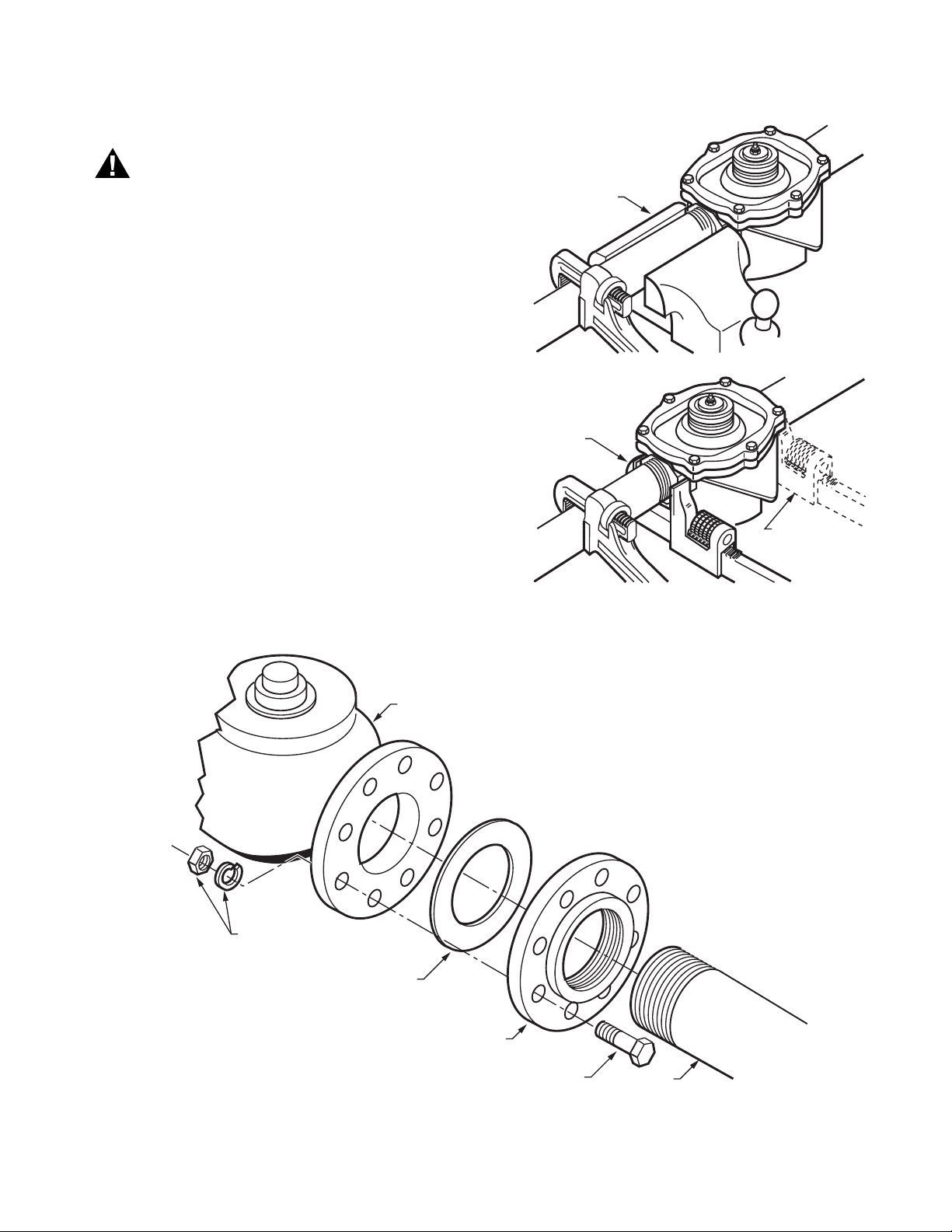
6. Apply a parallel jaw wrench only to the flat next to the
pipe being inserted (Fig. 5). A wrench applied to the
valve body itself, or to the end farthest from the pipe
being inserted, may distort the casting, causing a
malfunction. Do not use the valve for a lever.
7. Be sure the gas flow is in the same direction as the arrow
on the bottom of the valve body.
8. Use two threaded companion flanges, two gaskets
(included with valve), and 16 bolts (with washers and
nuts) for mounting a 4 in.-V5055 Valve. Mount a
threaded flange and gasket on each end of the valve as
shown in Fig. 6. Then screw the pipes into the threaded
flanges. Apply dope sparingly, and use wrenches and
vises properly as shown in Fig. 4 and 5.
9. Make sure the power supply is disconnected from
the valve actuator. Then mount the actuator on the valve
body and complete the electrical and linkage
connections following the instructions packed with the
actuator.
60-2307—16 8
OPERATION AND CHECKOUT
Operation
A V5055 Industrial Gas Valve is operated by a V4055, V4062,
or V9055 Fluid Power Gas Valve Actuator. The valve opens
when the actuator is energized, and closes when power is
removed. When closed, the valve seals off against the
rated close-off pressure with no power applied. For further
information, refer to the Instructions for the actuator.
Page 9
Checkout
V5055A-F INDUSTRIAL GAS VALVES
WARNING
Explosion Hazard.
Can cause serious injury, death or property
damage.
Do not allow fuel to accumulate in the combustion
chamber. If fuel is allowed to enter the chamber
for longer than a few seconds without igniting, an
explosive mixture could result.
CORRECT:
VISE GRIPS END
NEXT TO PIPE
BEING INSERTED
CORRECT:
WRENCH CORRECTLY
APPLIED NEXT
TO PIPE BEING
INSERTED
INCORRECT:
WRENCH HERE
STRAINS
VALVE BODY
Fig. 5. Installing a 3/4 through 3 in. V5055 Valve.
M9580
NUT AND WASHER
(NOT INCLUDED)
GASKET
(2 INCLUDED WITH VALVE)
4 IN. VALVE
THREADED COMPANION
FLANGE (2 - NOT INCLUDED)
5/8 X 3 IN. [76] BOLT
(16 - NOT INCLUDED)
Fig. 6. Installing a 4 in. V5055 Valve.
4 IN. PIPE
M9581
9 60-2307—16
Page 10
V5055A-F INDUSTRIAL GAS VALVES
CAUTION
Equipment Damage Hazard.
Operation without proper checkout can damage the
equipment.
1. Do not put the system into service until you have
satisfactorily completed the following Valve Leak
Test, all applicable tests described in the Checkout
section of the Instructions for the flame safeguard
control, and any other tests required by the burner
manufacturer.
2. All tests must be performed by a trained,
experienced flame safeguard control technician.
3. Close all manual fuel shutoff valves as soon as
trouble occurs.
After the installation is complete, cycle the valve several times
with the manual fuel shutoff cock closed. Make sure the valve
and actuator function properly. Also perform the Valve Leak
Test that follows before putting the valve into service.
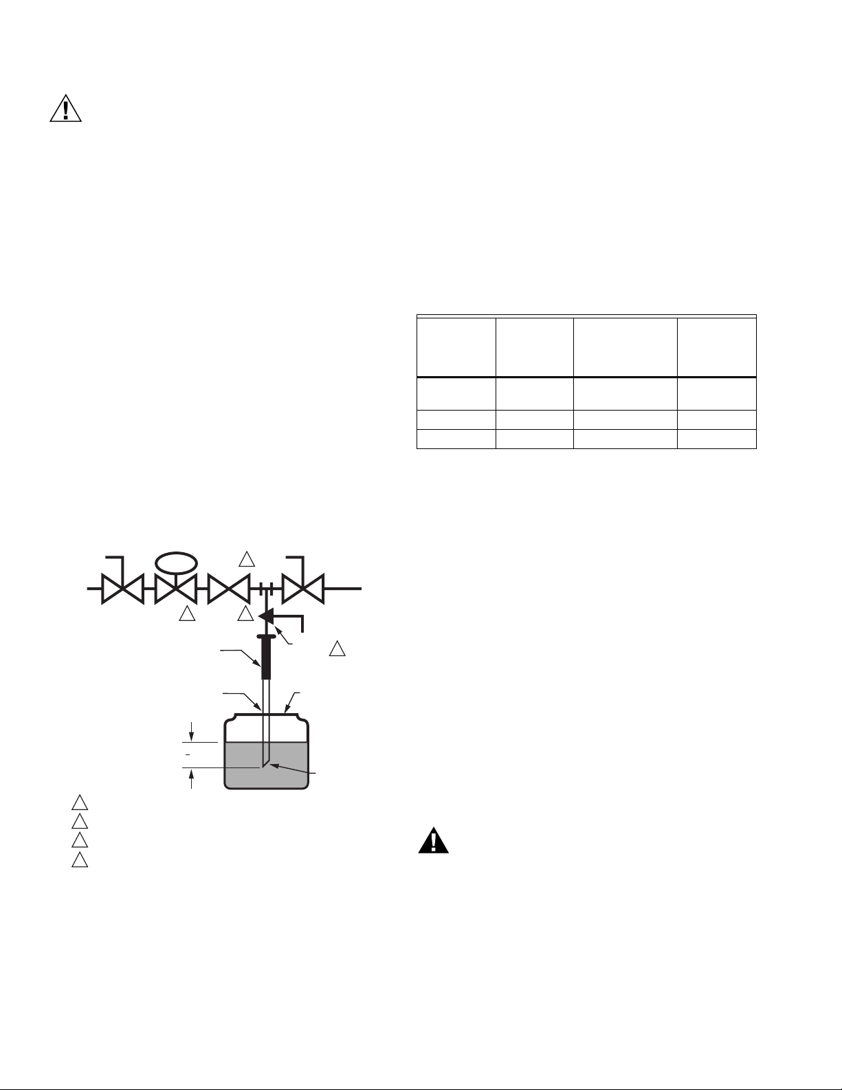
Valve Leak Test (Fig. 7)
This is a test for checking the closure tightness of a gas
safety shutoff valve. It should be performed by qualified
personnel during the initial startup of a burner system, or
whenever the valve or valve bonnet is replaced (see
Service Information section). It is recommended that this
test also be included in the scheduled inspection and
maintenance procedures. For a periodic inspection test,
follow steps 1, 3, 4, 5, 8, 9, 10, 12, 13, 16, and 17.
6. Open the upstream manual gas cock (A).
7. Run the safety shutoff valve (C) to its fully open position
(through the safety system); then immediately
de-energize the system to close the valve.
8. Immerse a 1/4 in. tube vertically 1/2 in. (12.7 mm) into
a jar of water.
9. Slowly open the test petcock (F).
10. When the rate of bubbles coming through the water
stabilizes, count the number of bubbles appearing during
a ten-second period. Each bubble appearing during a
ten-second period represents a flow rate of
approximately 0.001 cfh.
To meet U.S. requirements, leakage must not exceed the
values listed in Table 5.
Table 7. Allowable Leakage for V5055 Valves.
V5055 Pipe
Size (in.)
3/4, 1, 1-1/4,
Allowable
leakage
a,b
(cc/hr)
Maximum
Number of
bubbles per 10
sec.
573 14 6.7
Minimum
Number of
Seconds for
10 bubbles
1-1/2
2, 2-1/2, 3 940 24 4.1
4 1254 33 3.03
a
Based on natural gas at standard conditions, test pressures
provided by ANSI Z21.21, Section 2.4.2 and a maximum of
235 cc/hr (air) per inch of seal-off diameter. Seal-off diameter
is not to be confused with pipe size.
b
V5055F leakage rate is 1 bubble in 7.6 seconds.
DABC E
LEAK
4
TEST
TAP
GAS
SUPPLY
UPSTREAM
MANUAL
GAS COCK
CAN ALSO BE A PERMANENT PETCOCK.
1
PRV = PRESSURE REGULATING VALVE.
2
3
SSOV = SAFETY SHUTOFF VALVE.
USE ONLY ONE OF THE DOWNSTREAM TAPS ON THE SS0V.
4
PRV
SSOV
2 3
1/4 IN. (6 MM)
FLEXIBLE
TUBING
1/4 IN. (6 MM)
ALUMINUM OR
COPPER PILOT
TUBING
1
(13 MM)
2
DOWNSTREAM
MANUAL
GAS COCK
BURNER
F
MANUAL
TEST
PETCOCK
JAR OR GLASS
WITH WATER
CUT AT
45 DEGREE
ANGLE
1
M9547F
Fig. 7. Valve leak test.
1. De-energize the control system to assure that there is no
power to the safety shutoff valve (C) shown in Fig. 7.
2. Close the upstream manual gas cock (A).
3. Make sure the manual test petcock (F) is closed in the
leak test tap assembly (D).
4. Remove the leak test tap plug and connect the test
apparatus to the Leak Tap (D).
5. Close the downstream manual gas cock (E).
NOTE: For international leak test requirements, contact the
office of the appropriate approval agency.
After the test:
11. Close the upstream manual gas cock (A).
12. Close the test petcock (F), remove the test apparatus,
and replace the leak test tap plug (D).
13. Open the upstream manual gas cock (A) and energize
the safety shutoff valve (C).
14. Test with soap bubbles to assure that there is no leak
at the test tap (D).
15. De-energize the safety shutoff valve (C).
16. Open the downstream manual gas cock (E).
17. Restore the system to normal operation. If two safety
shutoff valves are utilized, each V5055 valve is to be
checked for tightness of closure.
SERVICE INFORMATION
WARNING
Explosion and Electrical Shock Hazard.
Can cause serious injury, death or property
damage.
1. Before servicing, turn off the gas supply and
disconnect all electrical power to the valve actuator.
2. Only qualified service technicians should attempt
to service or repair flame safeguard controls and
burner systems.
3. Do not disassemble the valve bonnet assembly;
the valve seat is not replaceable.
4. Failure to properly position and seat the seals in the
valve body may result in a hazardous gas leak.
60-2307—16 10
Page 11

V5055A-F INDUSTRIAL GAS VALVES
Scheduled Inspection and Maintenance
Setup and follow a schedule for periodic inspection and
maintenance, including the burner, all other controls, and the
valve(s) and actuator(s) for leaking oil. It is recommended that
the Valve Leak Test in the Checkout section be included in this
schedule. Refer to the Instructions for the primary safety
control for more information.
Valve Checkout for Oil Leakage from Actuator
1. Turn off the gas supply at the manual shutoff valve
located upstream from the valve(s) being serviced.
2. Shut off all electrical power to the valve actuator(s).
3. Mark and disconnect the wires from the actuator termi-
nals. Remove conduit and disengage the damper linkage assembly (if applicable).
4. Loosen the two set screws from the valve to lift off the
actuator.
5. If the actuator is to be replaced and it did not leak
hydraulic fluid, skip to Step 11.
NOTE: It is good practice to inspect the inside of the
valve whenever the actuator is replaced. To do
so, remove the bonnet assembly, inspect the
valve and bonnet. If all is well, proceed to Step 7.
6. If the actuator leaked hydraulic fluid onto the valve (the
fluid is red), it must be cleaned off from the valve and
bonnet assembly.
a. Wipe off the outer valve body.
b. Remove the valve bonnet bolts and lift off the bonnet.
10. After positioning the bonnet assembly, replace the
screws removed earlier.
NOTE: When replacing the bonnet assembly on the 4”
valve, it must be drawn evenly into the valve
body. Finger tighten the 8 screws. Draw the
bonnet assembly into the valve by tightening, in
order, screws 1, 5, 7, 3 (two turns each).
Repeat until the assembly is seated. Tighten
the remaining screws.
11. Remount the actuator on the bonnet assembly. Tighten
the two set screws (50-60 inch pounds).
12. Replace the damper crank arm assembly.
13. Re-attach the wires removed from the actuator terminals
and turn on the electrical power.
14. With the gas still off, cycle the actuator to check for
proper mechanical operation.
CAUTION
Be sure to perform a bonnet seal and seat leak
check after installation.
Be sure to read and follow all instructions that come
with the actuators, valves, seal and bonnet kits.
Valve Bonnet Replacement
The entire valve bonnet may be replaced without removing the
valve body from the gas line. Do not disassemble the valve
bonnet assembly; the valve seat is not replaceable.
NOTE: V5055/V5097C and E Valves have additional
internal springs that will push the bonnet up as
the bolts are loosened.
c. Inspect the inside of the valve.
IMPORTANT
If fluid is present on the inside surfaces of the valve
body or bonnet surfaces, the bonnet assembly or
entire valve must be replaced. For part numbers, refer
to “Replacement Parts:” on page 4.
d. If the inside surfaces are clear of hydraulic fluid,
clean the bonnet assembly and be sure to remove all
hydraulic fluid from the inside and outside of the
actuator mounting curb. This is the “cup-like” area
around the valve stem. Avoid using a cleaning solution as it may damage the rubber seals used in the
valve.
7. If the valve bonnet assembly is in good condition and is
not replaced, replace the bonnet seal. Do not reuse the
old bonnet seal. See “Replacement Parts:” on page 4 for
the seal number.
8. Coat seals with grease provided and position in valve
body/bonnet assembly.
9. Carefully seat the bonnet assembly on the valve body.
Be sure the seals are in their proper position. On those
valves with a spring below the disc, be sure the spring is
centered in the indentation on the inside of the valve
body.
For part numbers, refer to Replacement Parts in the
Specifications section. Complete instructions for replacing the
bonnet assembly are included with the replacement part.
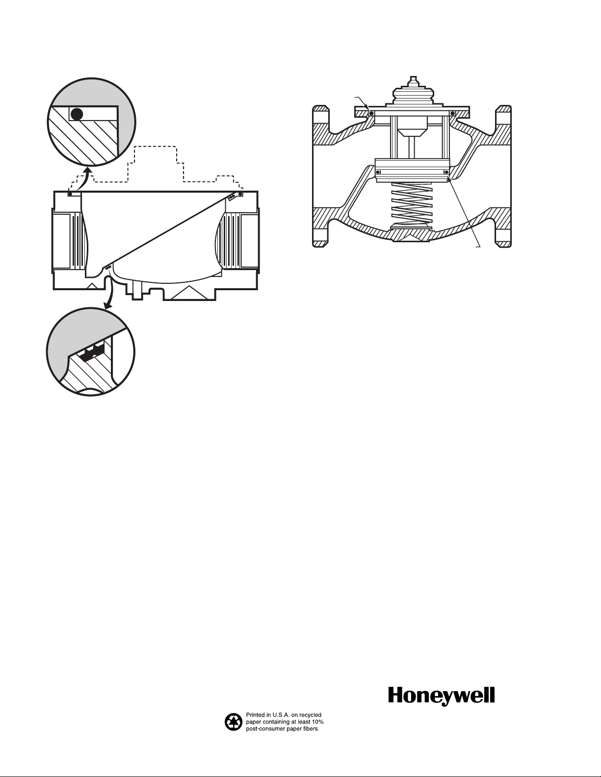
Replacement of Seals (Fig. 8 or 9)
When removing the bonnet to inspect and clean the valve,
install new seals (see Replacement Parts in Specifications
section). Coat the new seals with the grease provided, and
position them in the valve body as shown in Fig. 8 or 9.
Failure to properly position and seat the seals in the valve body
may result in a hazardous gas leak.
After the new bonnet assembly is installed, or the bonnet is
removed for any reason, check for gas leakage around the
bonnet seal. Turn on the gas at the manual valve. Paint the
seal area with a rich soap and water solution. Bubbles indicate
a gas leak. If a leak is detected, check to see that the bonnet
screws are tight. If necessary, turn off the gas again and
remove the bonnet to be sure the seals are properly seated.
Table 8. Gas Valve Replacement Seals.
Replacement Seal
Assy # Valve Size (in in.)
133393A 3/4, 1, 1-1/4, 1-1/2
133392A 2, 2-1/2, 3
137253A 4
11 60-2307—16
Page 12
V5055A-F INDUSTRIAL GAS VALVES
BONNET SEAL
LARGE SEAL
VALVE SEAL
Fig. 8. Proper positions of valve and bonnet
seals in 3/4 through 3 in. valves.
M9578
SMALL SEAL
Fig. 9. Proper positions of valve and
bonnet seals in 4 in. valves.
M9579
Automation and Control Solutions
Honeywell International Inc. Honeywell Limited-Honeywell Limitée
1985 Douglas Drive North 35 Dynamic Drive
Golden Valley, MN 55422 Toronto, Ontario M1V 4Z9
customer.honeywell.com
® U.S. Registered Trademark
© 2008 Honeywell International Inc.
60-2307—16 M.S. Rev. 02-08
 Loading...