

Page 1
Kombi-DP Diaphragm Unit
RETROFIT AUTOMATIC DP CONTROLLER
Design
The diaphragm unit consists of:
• Diaphragm housing with connections for impulse tube and
valve
• Spindle and tappet
• Supply valve adapter to install impulse tube to supply
mains valve (suitable for V5000 Kombi-3-plus RED and
V5100 Stop Valve-3)
• 4 x 1 mm impulse tube with compression fittings, length
800 mm
• 4 mm Allan key to change the pre-setting
Materials
• Diaphragm housing, spindle and diaphragm spring made
of stainless steel
• Connection for impulse tube and valve, supply valve
adapter, compression fittings and tappet made of brass
• Diaphragm and soft seals made of EPDM
• Impulse tube made of copper
V5012C
PRODUCT DATA
Application
The V5012C Kombi-DP diaphragm unit is installed onto a
V5010 Kombi-3-plus BLUE or V5032 Kombi-2-plus return
mains balancing valve and connected to a V5000 Kombi-3plus RED or V5100 Stop Valve-3 supply mains valve with the
supplied impulse tube.
It is used in systems with variable volume flows, for example
two-pipe heating systems or district heating exchangers, and
supports a hydronic balance by keeping the differential
pressure over consumers at a constant pre-set level even
under changing flow conditions.
The V5012C Kombi-DP diaphragm unit can be fitted to the
Kombi-Valves at any time, even when the system is under
pressure and in operation – operation of the system does not
have to be interrupted to install the V5012C Kombi-DP.
Features
• Retrofittable without interrupting operation of the
system
• Rugged design
• Two pre-setting ranges available: 0.1...0.3 bar or
0.3...0.6 bar differential pressure
• Suitable for V5010 Kombi-3-plus BLUE DN10...DN40
and V5032 Kombi-2-plus DN15...DN40
Specifications
Medium Water or glycol-water mixture,
quality to VDI 2035
pH-value 8...9.5
Operating temperature 2...130°C (36...266°F)
Operating pressure max. 10 bar (145 psi)
Differential pressure max. 2.0 bar (29 psi)
Differential pressure
pre-setting range
Factory setting V5012C0103: 0.1 bar (1.45 psi)
k
vs (cv)-values see flow diagram and remarks
V5012C0103:
0.1…0.3 bar (1.45…4.35 psi)
V5012C0306:
0.3…0.6 bar (4.35...8.70 psi)
V5012C0306: 0.3 bar (4.35 psi)
on page 5
Honeywell • All rights reserved EN0H-0281GE25 R0805
Page 2
V5012C KOMBI-DP
Function
The V5012C Kombi-DP diaphragm unit is installed onto a
V5010 Kombi-3-plus or V5032 Kombi-2-plus return mains
balancing valve and connected to a supply mains valve with
the supplied 4 x 1mm copper impulse tube and compression
fittings. Suitable supply valves are the V5000 Kombi-3-plus
RED or the V5100 Stop Valve-3 which are both compatible
with the supply valve adapter of the V5012C Kombi-DP kit.
The pressure of the supply pipeline is led to the Kombi-DP via
the impulse tube and acts onto the top of the diaphragm, the
pressure of the return pipeline is led to the Kombi-DP through
the return valve and acts onto the bottom of the diaphragm.
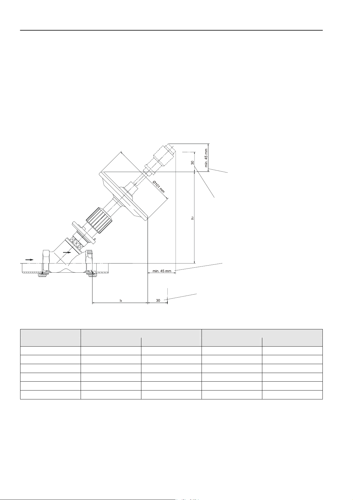
Dimensions
When the supply pressure increases, the diaphragm inside
the Kombi-DP is pushed down against the return pressure.
The diaphragm acts onto the insert of the connected return
valve and the flow is throttled.
When the supply pressure decreases, the diaphragm inside
the Kombi-DP is pushed open by the return pressure. The
diaphragm moves up, releasing the insert of the return valve
and the flow increases.
The desired differential pressure can be preset from 0.1...0.3
or from 0.3...0.6 bar, depending on the type used.
Additional space
required for optional
VA2503B001
Installation space
required
Additional space
required for optional
VA2503B001
Installation space
required
Fig. 1. V5012C Kombi-DP diaphragm unit with V5010 Kombi-3-plus BLUE or V5032 Kombi-2-plus
Table 1. Dimensions
Valve size V5012C0103 V5012C0306
DN h7 l5 h7 l5
10
15
20
25
32
40
135 95 145 102
135 95 146 103
150 100 161 111
150 90 161 101
185 105 196 116
185 100 196 111
NOTE: The V5012C is not supplied with valve.
All dimensions in mm.
EN0H-0281GE25 R0805 2 Honeywell • All rights reserved
Page 3

V5012C KOMBI-DP
Ordering Information
Table 2. OS-Nos. (OS=Ordering System)
Order text Pre-setting range OS-No.
V5012C Kombi-DP diaphragm unit 0.1…0.3 bar (1.45…4.35 psi) V5012C0103
0.3…0.6 bar (4.35...8.70 psi) V5012C0306
Box contents
• Diaphragm unit
• Supply valve adapter
• 4 mm Allan key
• Copper impulse tube 4 x 1 mm, length 800 mm
• Suitable compression fittings
• Installation and operating instructions
Accessories
Spring to reduce differential pressure pre-setting by 0,05 bar (0,73 psi)
for V5012C0103 only VA2502A002
External pre-setting device for installation between Kombi-Diaphragm
Unit and impulse tube
Angle adapter
for V5012C0103 only (not
with VA2504A001)
for all V5012 Kombi-DP VA2504A001
VA2503B001
Shutoff fitting R 1/4”
for all V5012 Kombi-DP VS5501A008
Service Parts
Spindle assembly
for all V5012C Kombi-DP
Compression fitting for 4 x 1 mm copper impulse tube
for all V5012 Kombi-DP VS5500A004
VS2500KDP1
Compression fitting for 6 x 1 mm copper impulse tube
for all V5012 Kombi-DP VS5500A008
Application Examples
Fig. 2. V5012C Kombi-DP in a two-pipe heating system
Honeywell • All rights reserved 3 EN0H-0281GE25 R0805
Fig. 3. V5012C Kombi-DP in a cooling system
Page 4

V5012C KOMBI-DP
Control Characteristics
NOTE: Below control characteristics refer to the combination of a V5012C Kombi-DP with a V5010 Kombi-3-plus BLUE or
V5032 Kombi-2-plus balancing valve.
Fig. 4. Control characteristic of V5012C0103, set at 0.1 bar Dp (factory setting)
EN0H-0281GE25 R0805 4 Honeywell • All rights reserved
Page 5

V5012C KOMBI-DP
Table 3. k
DN
kvs-value
cv-value
Liter/h Qmin
Qnom
Qmax
10 15 20 25 32 40
1.50 1.50 3.50 3.50 5.50 5.50
1.76 1.76 4.10 4.10 6.44 6.44
20 20 40 40 80 80
500 500 1,000 1,000 2,000 2,000
750 750 1,500 1,500 2,500 2,500
NOTE: The pump pressure must be set at least 0.1 bar above the pre-setting value, e.g. Dp 0.3 Î P
bar. The total pressure drop across supply and return valve, taking the V5012C Kombi-DP pre-setting into account, can
be calculated with Honeywell’s Valve Sizing Software at www.honeywell-valvesizing.com.
The V5012C0103 is factory set to 0.1 bar. The pre-setting can be increased to max. 0.3 bar. In that case the control
curve as displayed in Fig. 4 moves in parallel to the pre-setting value.
The V5012C0306 is factory set to 0.3 bar. The pre-setting can be increased to max. 0.6 bar. The control curve as
displayed in Fig. 4 moves in parallel to the pre-setting value.
In some special cases, e.g. heating systems with unrestrichted TRVs, the flow can additionally be throttled by reducing
the pre-setting value of the balancing valve.
Table 4. Effect of different valve pre-settings on k
Pre-setting of Balancing Valve
DN 1.5 1.4 1.2 1.0 0.8 0.6 0.4
10
15
20
25
32
40
1.50 1.45 1.35 1.25 1.15 0.95 0.70
1.50 1.45 1.35 1.25 1.15 0.95 0.70
3.50 3.40 3.30 3.10 2.80 2.45 1.80
3.50 3.40 3.30 3.10 2.80 2.45 1.80
— — — 5.50 5.20 4.45 —
— — — 5.50 5.20 4.45 —
NOTE: The V5010 Kombi-3-plus BLUE or V5032 Kombi-2-plus balancing valve has to be pre-set to 1.5 (sizes DN10...DN25)
or to 1.0 (sizes DN32...DN40) when used with the V5012C Kombi-DP diaphragm unit. Lower pre-settings can be used
to further throttle down the flow, see Table 4 on page 5.
vs-values and flow rates
0 0,4 bar; Dp 0,6 Î P0 0,7
vs-value
Honeywell • All rights reserved 5 EN0H-0281GE25 R0805
Page 6
V5012C KOMBI-DP
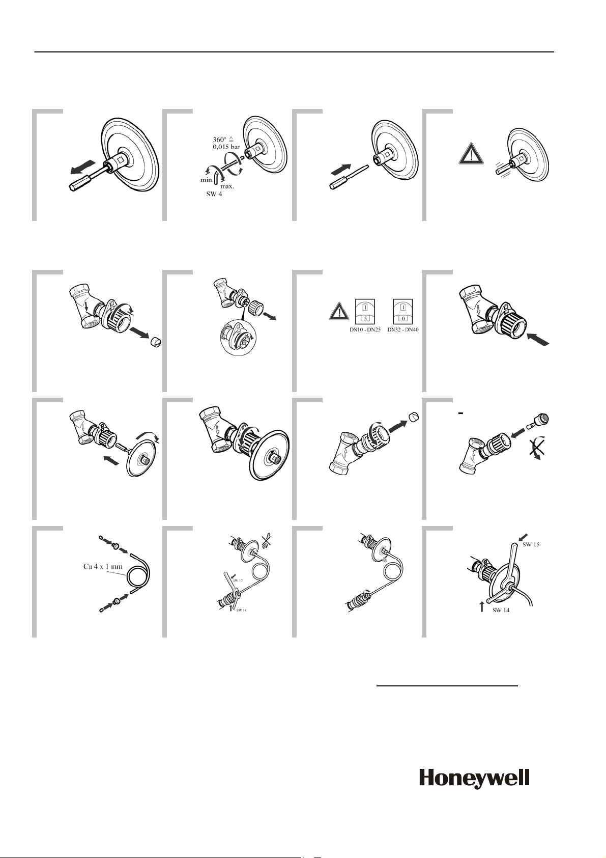
Installation and Setup
Changing the pre-setting
1
2 3 4
Note: Factory setting is 0.1 bar for V5012C0103 and 0.3 bar for V5012C0306.
Installation
1
Return valve:
V5010 Kombi-3-plus BLUE
or V5032 Kombi-2-plus
5
2 3 4
See 3
6
7 8
Spindle stays loose after first
removal
Supply valve:
V5000 Kombi-3-plus RED
or V5100 Stop Valve-3
9 10 11 12
Supplied with unit
Vent over diaphragm
connection
For more information on Honeywell Balancing and Pipeline Valves see www.honeywell-valvesizing.com
ACS Control Products
Honeywell GmbH
Möhnestraße 55
59755 Arnsberg, Germany
Phone: +49 (2932) 9880
Fax: +49 (2932) 988324
www.honeywell.com
EN0H-0281GE25 R0805
August 2005
© 2005 Honeywell International Inc.
Subject to change • All rights reserved
Manufactured for and on behalf of the Environmental and Combustion
Controls Division of Honeywell Technologies Sàrl, Ecublens,
Roude du Bois 37, Switzerland or by its Authorized Representative.
Insert but do not screw in
.
 Loading...