

Honeywell V5004TF Installation Instructions Manual
V5004TF
Installation instructions Einbauanleitung
Keep instructions for later use!
Anleitung zum späteren Gebrauch
aufbewahren!
32336560-001
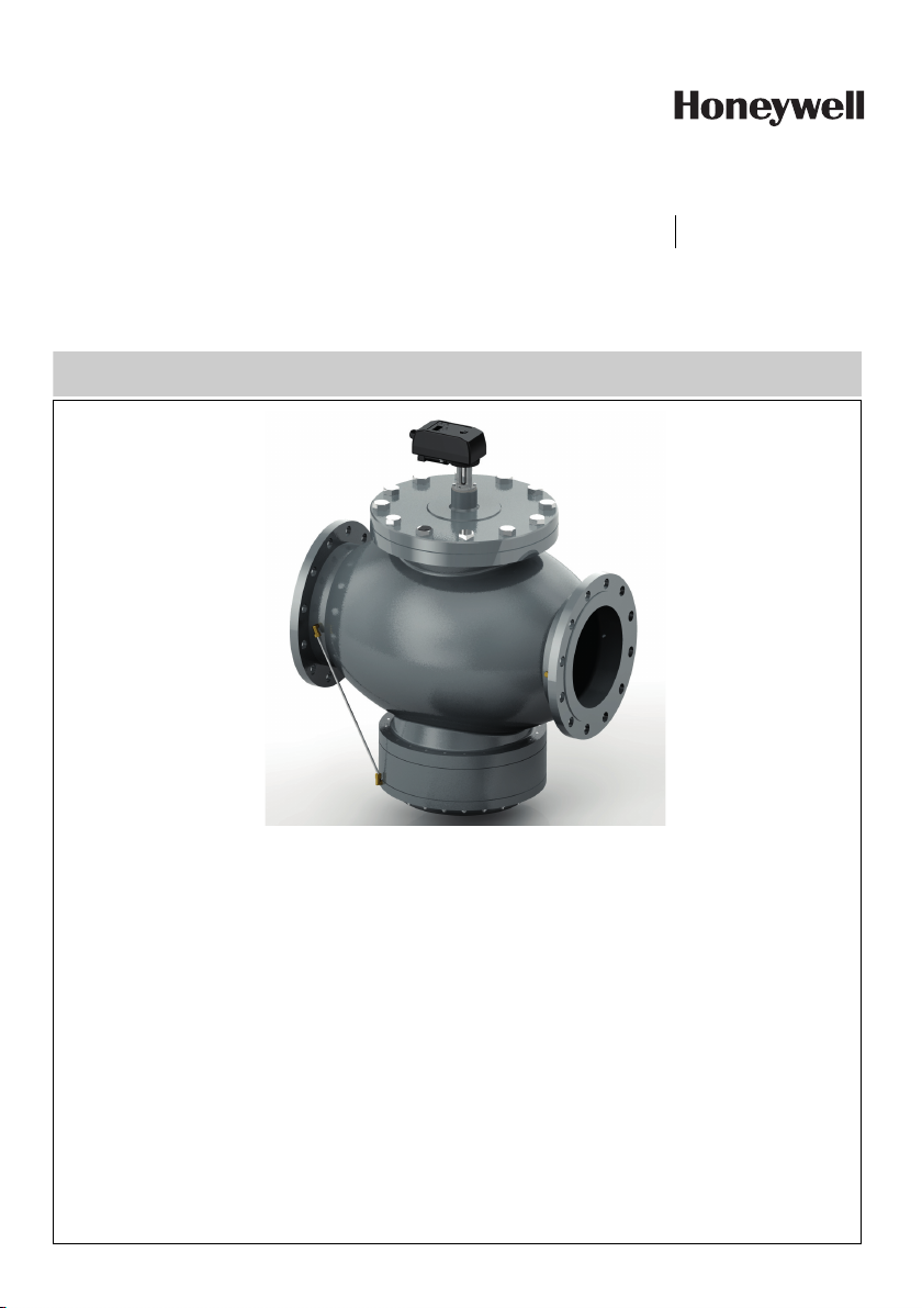
Kombi-QM Pressure Independent Balancing and Control Valve
Kombi-QM Druckunabhängiges Strangregulier- und Regelventil

GB
1 Actuator's features. . . . . . . . . . . . . . . . . . . 3
2 Installation Instructions . . . . . . . . . . . . . . . 3
3 External Interface . . . . . . . . . . . . . . . . . . . 6
4 Control Method . . . . . . . . . . . . . . . . . . . . . 7
5 Initial Setting . . . . . . . . . . . . . . . . . . . . . . . 7
6 Ratio of Value of Flow According to Flow
Curve . . . . . . . . . . . . . . . . . . . . . . . . . . . . . 9
7 Manual Override Operation . . . . . . . . . . . 10
8 General . . . . . . . . . . . . . . . . . . . . . . . . . . 10
D
1 Funktionsmerkmale des Stellantriebs . . . 11
2 Einbauanleitung. . . . . . . . . . . . . . . . . . . . 11
3 Externe Schnittstelle . . . . . . . . . . . . . . . . 14
4 Regelmethode . . . . . . . . . . . . . . . . . . . . .15
5 Anfangs-Einstellung. . . . . . . . . . . . . . . . . 15
6 Verhältnis des Volumenstromwerts gemäß
Volumenstromkennlinie . . . . . . . . . . . . . .18
7 Handbetätigung . . . . . . . . . . . . . . . . . . . .18
8 Allgemeines . . . . . . . . . . . . . . . . . . . . . . . 18
MU0H-2327GE23 R0618 2 Honeywell GmbH

GB
1 Actuator's features
• Proportional control
• analogue (voltage and current), PWM, 3 points and ON/
OFF
• Position detecting
• 4-digit display
• 3 buttons to set parameters
• Position control method to set actuator
OS-No. Flow [I/h] ∆ [kPa]
at 30%
flow
V5004TF1050 2000 - 20000 21 25 31 40 600
V5004TF1065 3000 - 30000 26 29 30 30 600
V5004TF1080 3000 - 30000 23 25 30 30 600
V5004TF1100 5500 - 55000 16 20 24 30 600
V5004TF1125 9000 - 90000 21 25 31 35 600
V5004TF1150 15000 - 150000 31 35 41 50 600
V5004TF1200LF 20000 - 200000 31 35 36 40 400
V5004TF1200HF 30000 - 300000 32 37 38 40 400
V5004TF1250LF 30000 - 300000 30 30 33 40 400
V5004TF1250HF 50000 - 500000 38 49 58 65 400
2. To set the flow on the V5004TF use the digital display
and three buttons on the Smart actuator.
When it is switched on, the Zero Detection function
automatically starts: the display shows “Go 0“. Wait
while the actuator is running and the end stroke is
found: finally the display will change to “0”.
To enter the settings browser, press the button MODE.
Press UP and DOWN buttons to select the setting.
Press MODE to show different options and browse
using UP and DOWN buttons. Once the option is found,
press MODE to confirm as the selection.
2 Installation Instructions
1. Mount the valve with the arrow in the direction of the
flow
CAUTION!
Mounting it in the wrong direction may damage the
system and the valve itself.
If flow reversal is possible, a non-return valve should be
mounted.
Minimum differential pressure above which the valve begins
to exercise its regulating effect:
Startup Pressure
∆[kPa]
at 50%
flow
SET1 Input indication selection with internal
SET2 Control signal selection
SET3 Min. flow rate setting
SET4 Max. flow rate setting
SET5 Setting display mode during operation
SET6 Rotation angle compensation
SET7 Flow rate offset compensation
SET8 Power failure mode
SET9 Flow rate unit selection
SET10 Control curve selection
SET11 Max. voltage control signal
SET12 Min. voltage control signal
SET13 Actuator rotation speed
SET14 Feedback signal selection
∆[kPa]
at 80% flow
control signal
∆[kPa]
at 100%
flow
∆[kPa]
MU0H-2327GE23 R0618 3 Honeywell GmbH

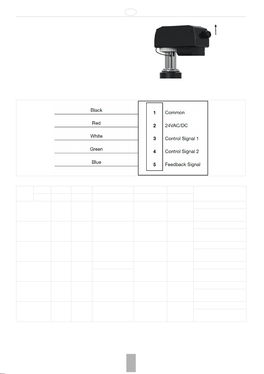
1 Display
1
3
2
4
5
2 Button UP
3 Button MODE
4 Button DOWN
5 Manual override
GB
Provided the differential pressure is higher than the start up
pressure, the valve keeps flow constant at the set value.
3. Operating Control
To ensure that the valve is working in its operating differential
pressure range.
Measure the differential pressure across the valve as shown
in the picture below.
2.1 M5004
2.1.1Application
Electromotive actuators M5004 - 24V are used with many
kind of control systems used for HVAC applications, including
ON/OFF, floating, proportional managed by thermostat or
BMS handling analogue signals or PWM digital, of HVAC
2.1.2Dimensions
Overview
4. Maintenance and Cleaning
Use a damp cloth to clean the actuator.
Do not use any detergent or chemical product that may
seriously damage or compromise the function of the valve.
installations where V5004TF PICV balancing valves are
used; in order to properly set the presetting, see the specific
section devoted to actuator setting.
For further information about electrical connections, see the
specific section.
Dimensions in mm
2.1.3Approvals
•CE
Honeywell GmbH 4 MU0H-2327GE23 R0618

GB
2.1.4Technical Data
Operating temperatures
Ambient temperature range: -20°C…+60°C*
Storage temperature range: -20°C...+80°C*
Specifications
Weight: 0.975 kg
Power supply: 24V AC/DC – 50/60 Hz
Connecting cable: 18 AWG
Connection to valve: 8mm square. Easy fitting
gear
Operating life: 50.000 cycles
Control signal: 0(2)-10V 0(4)-20mA
(with 500 Ω resistor*)
ON/OFF
3 points floating PWM
Power consumption: 5 W; 2.5 W stand-by
Nominal torque: 10 Nm Max, self-limited at 7
Nm
Current absorption: 80 mA, Load max 380 mA
Feedback: 0(4) - 20 mA and 0(2) – 10 V
Manual Override: Through release button and
6mm Allen key
Protection class / IP Rating: II / IP54
Motor: Brushless DC motor
Running speed: Selectable: 1 RPM or 1.5
RPM
Fail safe: Through additional battery
*1no condensation
1
1
2.1.5Installation
If the actuator M5004 is purchased with the valve Honeywell
V5004TF, it is already installed onto the valve. If it is bought
as a spare part, follow the next procedure:
1. Completely open the valve with an 8 mm spanner (max
torque 7 Nm)
2. Install the actuator in the same position of that has been
previously removed
3. Insert the three pins in the specific buttonholes on the
fixing plate
4. Turn the fixing ring
5. Close the valve by means of the actuator which has to
be electrically connected
6. If the actuator reaches the end-stroke before the valve
is completely closed, adjust the actuator mounting
position
7. Unplug and plug the power to the actuator to perform a
new Zero Detection cycle.
Be sure the actuator is not mounted upside down to avoid any
damage due to condensation from the valve stem. Please
note that care must be taken to actuator installation: little
angular deviations can compromise the correct actuator
operation
2.1.6Settings
Actuator M5004 is delivered already set at max flow rate of
the valve where it is mounted (SET 4); if it is bought as spare
part, the customer must inform Honeywell about valve type
the actuator will be mounted on, allowing Honeywell's
technicians to properly set it.
When the actuator is powered, the valve V5004TF
corresponding code is displayed on the 4 digits screen. Verify
using the table at the end of the next page that the shown
code corresponds the installed valve. If an issue occurs,
contact Honeywell’s technicians.
To set the actuator, use the 3 buttons and the display on the
upper side. When it is switched on, the Zero Detection
function automatically starts: the display shows “Go 0“. Do not
carry out any operation while the actuator is running and the
end stroke is found: finally it displays “0”. To enter the settings
browser, push the button MODE. Use UP and DOWN buttons
to select the parameter, then push MODE to show different
options (option browsing is carried out through UP and
DOWN buttons); push MODE to confirm the selection.
SET1 Input indication selection with internal
control signal
SET2 Control signal selection
SET3 Min. flow setting
SET4 Max. flow setting
SET5 Setting display mode during operation
SET6 Rotation angle compensation
SET7 Flow offset compensation
SET8 Power failure mode
SET9 Flow rate unit selection
SET10 Control curve selection
SET11 Max. voltage control signal
SET12 Min. voltage control signal
SET13 Actuator rotation speed
SET14 Feedback signal selection
MU0H-2327GE23 R0618 5 Honeywell GmbH
GB
2
1
2.1.7Removal
If the actuator has to be removed, follow the next procedure:
1. Turn the connection ring between valve and actuator
2. Remove the actuator
3 External Interface
3.1 Wires indication
3.2 Actuator Wiring Guide
Number 1 2 3 4 5
Input
Colour Black Red White Green Blue
Internal control Common 24 AC/DC
Voltage signal Common 24 AC/DC
Current signal Common 24 AC/DC
ON/OFF signal Common 24 AC/DC
3 points floating Common 24 AC/DC Opening 24 V AC/DC
PWM control Common 24 AC/DC PWM signal
• and are power cables
• and are signal cables
• is the exclusive feedback cable
0 - 10 V DC
2 - 10 V DC
0 - 20 mA
4 - 20 mA
24 V DC (open) Feedback:
0 V (close)
Closing 24
V AC/DC
Feedback:
0(2) - 10 V
0(4) - 20 mA
Feedback:
0(2) - 10 V
0(4) - 20 mA
Feedback:
0(2) - 10 V
0(4) - 20 mA
0(2) - 10 V
0(4) - 20 mA
Feedback:
0(2) - 10 V
0(4) - 20 mA
Feedback:
0(2) - 10 V
0(4) - 20 mA
Remarks
Power: cable 1 - 2
Power: cable 1 - 2
Voltage signal: cable 1 - 3
Power: cable 1 - 2
Current signal: cable 1 - 3
Power: cable 1 - 2
ON/OFF signal: cable 1 - 3
Power: cable 1 - 2
Floating 3 points: cable 3 - 4
Power: cable 1 - 2
PWM control: cable 1 - 3
Honeywell GmbH 6 MU0H-2327GE23 R0618
 Loading...