

Page 1

V2075, V2077
Flowshare Valve
THERMOSTATIC TWO-WAY FLOWSHARE VALVE
PRODUCT DATA
Application
Thermostatic flowshare valves control the output of radiators
in vertical one-pipe heating systems. Heating water not required is diverted through the bypass into the return. The
valve is controlled by a Honeywell radiator thermostat.
In the starting position the valve is open to the pre-set value.
The radiator proportion can be pre-set from 35 to 60% and is
supplied with a setting of 35%. The valve is suitable for use
with all Honeywell radiator thermostats.
An additional extension tail, injector and lockshield valve can
be installed to avoid heating up of the radiator through the
return – see ‘Accessories’ on page 3.
Features
• Stepless, concealed pre-setting of the flow, factory set
at 35% radiator proportion
• Low noise
• Exchange of valve insert or O-ring insert without
draining
• With beige protection cap
Design
The Flowshare Valve consists of:
•
Valve housing PN10 with externally threaded connections
for pipe, bypass and radiator
•
Pre-settable valve insert
•
Protection cap
Materials
•
Valve housing made of red bronze RG5 according to
DIN 1705
•
Valve housing made of brass with EPDM O-rings
•
Spindle made of stainless steel
•
Protection cap made of beige plastic
Specifications
Medium
pH-value
Operating temperature
Operating pressure
Differential pressure
vs
-values
k
Thermostat thread
Closing dimensions
Heating water
8...9,5
max. 130°C (266°F)
max. 10 bar (232 p.s.i.)
max. 0,2 bar (2,9 p.s.i.)
2,1...2,7 depending on valve
housing, see table on 2
M30 x 1,5
11,5 mm
Function
The Flowshare Valve was designed for use with a radiator
thermostat. Depending on the room temperature heating
water is partly diverted through the outlet into the radiator and
partly through the bypass into the return pipeline. When the
room temperature falls the valve is opened by the radiator
thermostat and more heating water can flow into the radiator.
When the room temperature rises the valve is closed and the
heating water is diverted past the radiator into the bypass.
Copyright © 2001 Honeywell AG • All rights reserved EN0H-193GE25 R0101
Page 2
FLOWSHARE VALVE (V207 5, V20 77)
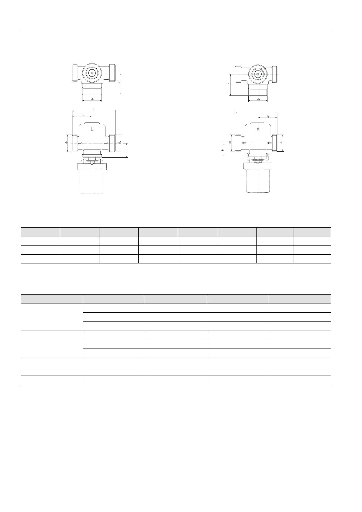
Dimensions
Fig. 1. Version for connection on the left Fig. 2. Version for connection on the right
NOTE: Valve is supplied without radiator thermostat but with protection cap.
Table 1: Dimensions
DN l l1 l2 d1 d2 d3 h
10 63,0 29,0 31,5 G 1/2" AG G 3/4" AG G 3/4" AG 22,0
15 65,5 30,5 34,0 G 3/4" AG G 3/4" AG G 7/8" AG 22,0
20 73,5 36,5 39,5 G1" AG G 1" AG G 1 1/8" AG 31,0
NOTE: All dimensions in mm unless stated otherwise.
Ordering information
Version Dim. Radiator proportion kvs-value OS-No.
Connection on the left
Connection on the right
Connection on the left 1/2“ 35...60% 2,1 V2077L0015
Connection on the right 1/2” 35...60% 2,1 V2077R0015
3/8" 35...60% 2,1 V2075L0010
1/2" 35...60% 2,1 V2075L0015
3/4" 35...60% 2,7 V2075L0020
3/8" 35...60% 2,1 V2075R0010
1/2" 35...60% 2,1 V2075R0015
3/4" 35...60% 2,7 V2075R0020
Two-way Flowshare Valve for Forster type heating systems
NOTE: Valves are supplied without union nuts but with three sealing rings.
EN0H-193GE25 R0101 2 Honeywell AG • All rights reserved
Page 3

Accessories
Pre-setting key tool to change radiator proportion
Connections for the valve inlet
Internally threaded tailpiece, nickel-plated
1/2" 1 01 01 75 015 000
3/4" 1 01 01 75 020 000
0 44 08 00 650 000
FLOWSHARE VALVE (V207 5, V20 77)
Connections for the valve outlet
Brass union-nut
for valves DN10 and
DN15
for valves DN20 0 20 18 15 020 000
Externally threaded brass tailpiece
1/2", for valves DN15 0 20 35 01 015 000
3/4", for valves DN20 0 20 35 01 020 000
0 20 18 15 015 000
Brass union-nut
for valves DN10 0 20 18 17 012 000
for valves DN15 0 20 18 15 015 000
for valves DN20 0 20 18 15 020 000
Brass soldering tailpiece
15 mm,
for valves DN15
22 mm,
for valves DN20
Steel welding tailpiece
1/2", for valves DN15 0 40 35 02 015 000
3/4”, for valves DN20 0 40 35 02 020 000
Adapter with olive connection
Connections for the valve bypass
Brass union-nut
3/4", for valves DN10 0 20 18 15 020 000
7/8", for valves DN15 0 20 18 17 078 000
1 1/8", for valves DN20 0 20 18 17 118 000
Internally threaded brass tailpiece
3/8", for valves DN 10 0 20 35 09 010 000
1/2", for valves DN 15 0 20 35 09 015 000
3/4", for valves DN 20 0 20 35 09 020 000
Adapter with olive connection (only required for
bypass tube 15 x 1,5 mm)
0 20 53 03 015 000
0 20 53 03 020 000
0 20 96 13 300 000
0 40 96 13 360 000
Reduction adapter
for valves DN20 and
radiators with 1/2" connection
0 20 35 12 015 000
Accessories to avoid heating up through the return
Note that the kvs-value of the combination is reduced, see
flow diagrams on pages 4 and 5.
Injector for installation in the bypass pipe
1/2" 1 05 01 65 015 000
3/4" 1 05 01 65 020 000
Extension tailpiece, is installed additionally to the injector, radiator is
shifted by approx. 7 cm
•
Version 1/2" radiator connection 1/2" external
•
Version 3/4" with reduction tailpiece 3/4" external - 1/2"
internal.
By this existing radiators can be replaced with new radiators
1/2” internal without replacing the valve.
1/2", for valves DN10
and DN15
3/4", for valves DN20 1 01 01 66 020 000
Special-lockshield, consisting of
•
Verafix-E, 1/2" straight with union nut and special tailpiece
1/2" external, or
•
Verafix-E, 3/4" straight with reduction tailpiece 3/4" exter-
nal - 1/2" internal. By this existing radiators can be replaced with new radiators 1/2” internal without replacing
the valve.
•
Union-nut and tailpiece for connection to T-piece of by-
pass.
1/2" 1 33 32 50 015 018
3/4" 1 33 32 50 020 018
0 00 35 13 015 000
Honeywell AG • All rights reserved 3 EN0H-193GE25 R0101
Page 4

FLOWSHARE VALVE (V207 5, V20 77)
k
l
Flow diagram DN10 and DN15
Valve DN10, DN15
ue
-va
v
Valve DN10, DN15 with
injector , ex tension and
special lockshield
Pre-setting
Table 2. kv-values and radiator proportion for DN10 and DN15
Pre-set-
ting
closed
P-Deviation
1K 2K 3K
k
v
% k
v
% k
v
% k
open
v
0 1,10 1,20 27 1,40 44 1,55 60 1,55 65
0,5 1,40 1,50 22 1,60 39 1,80 50 1,84 58
1 1,50 1,70 20 1,80 35 1,95 44 1,95 51
1,5 1,60 1,80 18 1,90 31 2,07 39 2,07 46
2 1,70 1,90 15 2,00 27 2,10 35 2,16 42
%
Table 3. kv-values and radiator proportion for DN10 and DN15 with
special lockshield, tailpiece and injector
P-Deviation
Pre-set-
ting
closed
1K 2K 3K
k
v
% k
v
% k
v
% k
v
0 1,06 1,15 25 1,32 40 1,45 55 1,45 60
0,5 1,32 1,40 20 1,49 35 1,65 46 1,67 53
1 1,40 1,59 19 1,64 32 1,75 41 1,75 47
1,5 1,50 1,64 17 1,72 30 1,85 36 1,85 43
2 1,60 1,70 15 1,80 27 1,90 32 1,90 39
EN0H-193GE25 R0101 4 Honeywell AG • All rights reserved
open
%
Page 5

Flow diagram DN2 0
k
l
FLOWSHARE VALVE (V207 5, V20 77)
Valve DN20
ue
-va
v
Valve DN10, DN15 with
injector, extension and
special lockshield
Pre-setting
Table 4. kv-values and radiator proportion for DN20
Pre-set-
ting
closed
P-Deviation
1K 2K 3K
k
v
% k
v
% k
v
% k
open
v
0 1,40 1,60 23 1,90 41 2,20 50 2,60 70
0,5 1,50 1,76 21 2,02 38 2,32 47 2,70 67
1 1,60 1,86 19 2,13 34 2,38 43 2,75 64
1,5 1,70 1,95 17 2,23 30 2,51 39 2,85 61
2 1,80 2,10 15 2,40 27 2,70 35 3,10 58
%
Table 5. kv-values and radiator proportion for DN20 with
special lockshield, tailpiece and injector
Pre-set-
ting
closed
P-Deviation
1K 2K 3K
k
v
% k
v
% k
v
% k
open
v
%
0 1,32 1,49 22 1,72 39 1,93 47 2,18 67
0,5 1,40 1,61 20 1,80 35 2,00 44 2,24 64
1 1,50 1,69 18 1,88 31 2,05 40 2,27 61
1,5 1,60 1,75 16 1,95 28 2,13 36 2,32 68
2 1,70 1,86 14 2,06 25 2,24 32 2,45 55
Honeywell AG • All rights reserved 5 EN0H-193GE25 R0101
Page 6

FLOWSHARE VALVE (V207 5, V20 77)
Home and Buil ding Control
Honeywell AG Phone: (49) 2932 9880
Zu den Ruhrwiesen 3 Fax: (49) 2932 988239
D-59755 Arnsberg-Neheim mng@honeywell.com http://europe.hbc.honeywell.com
EN0H-193GE25 R0101 6 Subject to change • All rights reserved
 Loading...