

Page 1
1/2
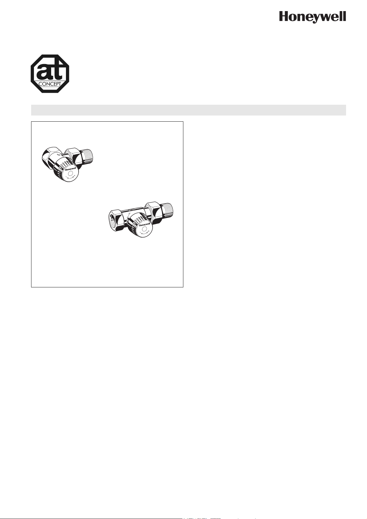
Angle to DIN
V2000SL
SL type TRV Body
RADIATOR VALVE WITH STROKE LIMITED CARTRIDGE
PRODUCT DATA
Application
Thermostatic radiator valve bodies (TRV bodies) are fitted on
the supply or return of radiators or heat exchangers. Together
with a radiator thermostat, for example the Thera-4, they
control the room temperature by regulating the flow of hot water
into the radiator. The temperature of different rooms is
controlled individually and energy is saved.
TRV bodies of this type have quiet operation and are fitted to
the supply of radiators on two-pipe systems with medium flow
rates.
The valve insert can be replaced while the system is running
1/2
Straight to DIN
and without draining using the service tool (see ‘Accessories’).
TRV bodies of this type are suitable for
• Honeywell radiator thermostats with M30 x 1.5 connection
• Certain Honeywell MT4 actuators
•
Honeywell Hometronic HR80 and Roomtronic HR40 actuators
AT-Concept
AT-Concept valves share the same valve housing design. The
valve insert can be replaced by any other AT-Concept valve
insert, i.e. BB, KV, UBG, SL, VS, FS, FV and SC.
Design
The thermostatic radiator valve body consists of:
• Valve housing PN10, DN10, 15 or 20 with
• internal thread connection to DIN2999 (ISO7) for threaded,
copper or precision steel pipe on inlet (compression ring
fittings see ‘Accessories’)
• external thread connection to DIN/ISO228 with union-nut
and radiator tailpiece on outlet
• angle to DIN and straight to DIN bodies with dimensions
according to EN215, Appendix A, Series D
• angle to NF and straight to NF bodies with dimensions
according to EN215, Appendix A, Series F
• Valve insert with SL type stroke limited cartridge
• Protection cap
• Union-nut and radiator tailpiece
Materials
• Angle/straight to NF: valve housing made of nickel-plated
hot-forged brass
• Angle/straight to DIN: valve housing made of nickel-plated
red bronze
• Valve insert made of brass with EPDM O-rings and soft seals
and stainless steel spindel
• Protection cap made of white plastic
• Union-nut and tailpiece made of nickel-plated brass
Honeywell y Subject to change EN0H-2107GE25 R0307
Features
• With adjustable stroke limitation
• Quiet operation
• Valve insert can be replaced while system is operating
and without draining the system
• Standard M30 x 1.5 thermostat connection
Specifications
Medium Heating water, water quality to
VDI2035
Operating temperature max. 130°C (266°F)
Operating pressure PN10
Differential pressure max. 1 bar (14.5 psi) –
max. 0.2 bar (2.9 psi) recommended
for quiet operation
k
(cv)-value DN10 1.70 (1.99)
v
DN15 1.85 (2.16)
DN20 1.95 (2.28)
Nominal flow 190 kg/h
Thermostat connection M30 x 1.5
Closing dimension 11.5 mm
Stroke 2.5 mm
Page 2
V2000SL - SL TYPE TRV BODY
Function
Thermostatic radiator valves enable individual control of room
temperature and thus save energy.
The TRV body is controlled by the radiator thermostat. Air from
the room passing over the sensor of the radiator thermostat
causes the sensor to expand when the temperature rises. The
sensor acts onto the valve spindle and this causes the TRV
body to close. When the temperature falls the sensor contracts
and the spring-loaded valve spindle is opened. The TRV opens
in proportion to the temperature of the sensor. Only the amount
of water required to maintain the room temperature set on the
radiator thermostat can flow into the radiator.
Identification
• White protection cap
• Brass valve insert with black plastic scale on top
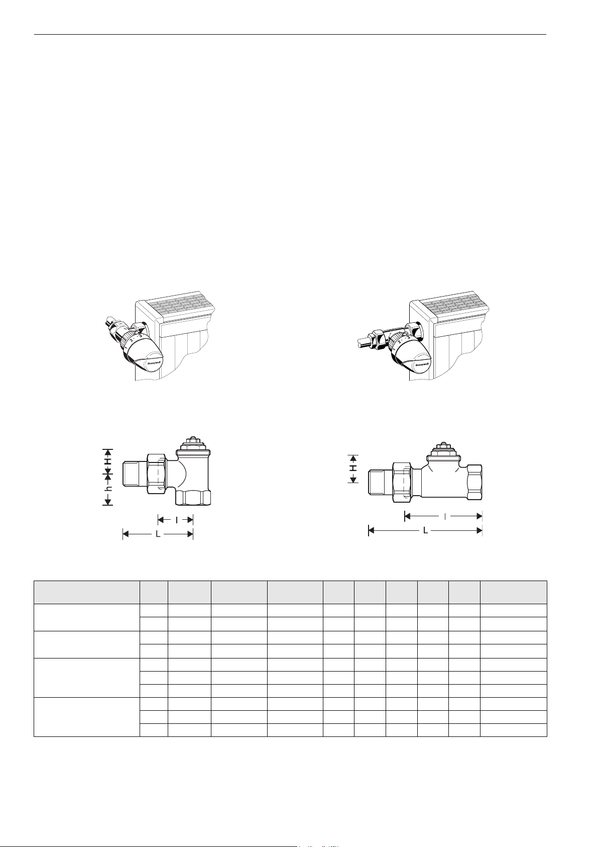
Installation Example
Please Note:
• To avoid stone deposit and corrosion the composition of the
medium should conform with VDI-Guideline 2035
• Additives have to be suitable for EPDM sealings
• System has to be flushed thoroughly before initial operation
with all valves fully open
• Any complaints or costs resulting from non-compliance with
above rules will not be accepted by Honeywell
• Please contact us if you should have any special requirements or needs
Pre-setting
Pre-setting is done by by first closing and then opening the
black pre-setting ring on the topside of the valve to the number
derived from the flow diagram. Pre-setting 10 is 1 complete turn
of the pre-setting screw.
Fig. 1. Angle Fig. 2. Straight
Dimensions and Ordering Information
Fig. 3. Angle Fig. 4. Straight
Table 1. Dimensions and OS-Nos (OS=Ordering System)
Body type DN EN215
certified
Angle to EN215 (D)
(Fig. 3)
Straight to EN215 (D)
(Fig. 4)
Angle to EN215 (F)
(Fig. 3)
15 • 1.85 (2.16) Rp
20 • 1.95 (2.28) Rp
15 • 1.85 (2.16) Rp
20 • 1.95 (2.28) Rp
10 • 1.70 (1.99) Rp
15 • 1.85 (2.16) Rp
20 1.95 (2.28) Rp
Straight to EN215 (F)
(Fig. 4)
10 • 1.70 (1.99) Rp 3/8" 50 75 — 26 — V2020DSL10
15 • 1.85 (2.16) Rp
20 1.95 (2.28) Rp
NOTE: All dimensions in mm unless stated otherwise.
kvs(cv)-
value
Pipe
l L h H h
2
connection
1
/2" 29 58 26 20 — V2000ESL15
3
/4" 34 66 29 19 — V2000ESL20
1
/2" 66 95 — 25 — V2000DSL15
3
/4" 74 106 — 25 — V2000DSL20
3
/8" 24 49 20 21 — V2020ESL10
1
/2" 26 53 23 22 — V2020ESL15
3
/4" 34 66 29 18 — V2020ESL20
1
/2" 55 82 — 26 — V2020DSL15
3
/4" 74 106 — 24 — V2020DSL20
OS-No.
EN0H-2107GE25 R0307 2 Honeywell y Subject to change
Page 3

Accessories
Pipe Connections Valve Accessories
Compression ring and nut
3/8" x 10 mm VA620A1010
3/8" x 12 mm VA620A1012
1/2" x 10 mm VA620A1510
1/2" x 12 mm VA620A1512
1/2" x 14 mm VA620A1514
1/2" x 15 mm VA620A1515
1/2" x 16 mm VA620A1516
3/4" x 18 mm VA620A2018
3/4" x 22 mm VA620A2022
NOTE: Support inserts have to be used for copper or soft
steel pipe with 1.0 mm wall thickness
Compression ring and nut with support insert (2 pcs
each)
3/8" x 12 mm VA621A1012
1/2" x 12 mm VA621A1512
1/2" x 15 mm VA621A1515
1/2" x 16 mm VA621A1516
3/4" x 18 mm VA621A2018
Compression ring and nut with support insert for
composite pipe (2 pcs each)
1/2" x 14 mm VA622B1514
1/2" x 16 mm VA622B1516
Manual handwheel cap
Pre-settable, with integrated
locking device
Pressure cap – for shutting off valves on radiator outlet
for valves DN10 (3/8") VA2202A010
for valves DN15 (1/2") VA2202A015
for valves DN20 (3/4") VA2202A020
Sealing ring for pressure cap
for valves DN10 (3/8") VA5090A010
for valves DN15 (1/2") VA5090A015
for valves DN20 (3/4") VA5090A020
Service tool to replace valve insert
for all sizes VA8200A001
Replacement valve insert
SL type VS1200SL01
V2000SL - SL TYPE TRV BODY
VA2200D001
Reduction piece
1" pipe > 1/2" valve VA6290A260
1 1/4" pipe > 1/2" valve VA6290A280
1" pipe > 3/4" valve VA6290A285
1 1/4" pipe > 3/4" valve VA6290A305
Radiator tailpiece with thread up to collar
for valves DN10 (3/8") VA5201A010
for valves DN15 (1/2") VA5201A015
for valves DN20 (3/4") VA5201A020
Soldering tailpiece
3/8" x 12 mm (for DN10) VA5230A010
1/2" x 15 mm (for DN15) VA5230A015
3/4" x 22 mm (for DN20) VA5230A020
Extended radiator tailpiece, nickel-plated, to be shortened
as required
3/8" x 70 mm (for DN10)
thread approx. 50 mm
1/2" x 76 mm (for DN15)
thread approx. 65 mm
3/4" x 70 mm (for DN20)
thread approx. 60 mm
VA5204A010
VA5204A015
VA5204A020
Honeywell y Subject to change 3 EN0H-2107GE25 R0307
Page 4

V2000SL - SL TYPE TRV BODY
Flow Diagram
1K 2K 3K
Pre-setting 1 2 3 4 5 7 17.5 = open = kvs
kv(cv)-value for DN10 0.25 (0.29) 0.50 (0.59) 0.70 (0.82) 1.00 (1.17) 1.25 (1.46) 1.50 (1.76) 1.70 (1.95)
kv(cv)-value for DN15 0.25 (0.29) 0.50 (0.59) 0.70 (0.82) 1.00 (1.17) 1.25 (1.46) 1.50 (1.76) 1.85 (2.16)
kv(cv)-value for DN20 0.25 (0.29) 0.50 (0.59) 0.70 (0.82) 1.00 (1.17) 1.25 (1.46) 1.50 (1.76) 1.95 (2.28)
NOTE: Pre-settings above 4 are unsuitable for operation with radiator thermostats and should only be used with actuators (open/
close operation).
P-Band 1K 2K 3K
kv-value 0.3 0.6 0.8
cv-value 0.35 0.70 0.94
Automation and Control Solutions
Honeywell GmbH
Hardhofweg
74821 Mosbach, Germany
Phone: +49 (6261) 810
Fax: +49 (6261) 81393
www.honeywell.com
EN0H-2107GE25 R0307
March 2007
© 2006 Honeywell International Inc.
Subject to change • All rights reserved
Manufactured for and on behalf of the Environmental and Combustion
Controls Division of Honeywell Technologies Sàrl, Ecublens, Route
du Bois 37, Switzerland or its authorized representative.
 Loading...