

Page 1
N8188-2V3 11/08 Rev. B
DUAL TEMPERATURE SENSOR
INSTALLATION AND OPERATING INSTRUCTIONS
INTRODUCTION
The Honeywell Ademco TS300 is a hardwired temperature monitor able to accurately detect variations in temperature. It
can monitor the temperature at the unit and at a remote location (using a T280R) simultaneously. Alarm annunciations
include a local piezo sounder and two programmable NO/NC outputs which activate when the mapped high or the low
limit(s) is exceeded, protecting equipment, property, and perishable items. The NO/NC alarm outputs may be delayed by
increments of one minute to allow for expected momentary temperature variations such as during a refrigeration unit's
defrost cycle. The audible alert, if programmed, sounds when the temperature limit is violated and can be silenced with
the press of a button for a programmed duration. The TS300 can accurately monitor any temperature within the range
from 32°F to 140°F (0°C to 60°C). A T280R Remote Temperature Probe may be used to monitor temperature within the
range from -40°F to 140°F (-40°C to 60°C) or to monitor temperature in a harsh environment.
INSTALLATION
Mount the unit on a wall at a convenient viewing height. For accurate temperature sensing at the unit, do not mount the
TS300 near any heat or cooling source. If the unit does not trip the panel, insure that the contact configuration (NO/NC)
as defined in the Setup Procedure agrees with that of the zone to which it is connected.
TO THE INSTALLER
Regular maintenance by the installer and frequent testing by the user are vital to continuous satisfactory operation of any
alarm system. The TS300 and the T280R should be tested periodically, at least once a month, depending on conditions.
The installer should assume the responsibility of developing and offering a regular maintenance program to the user as
well as acquainting the user with the proper operation and limitations of the alarm system and its component parts.
Recommendations must be included for a specific program of frequent testing to ensure the system's proper operation at
all times.
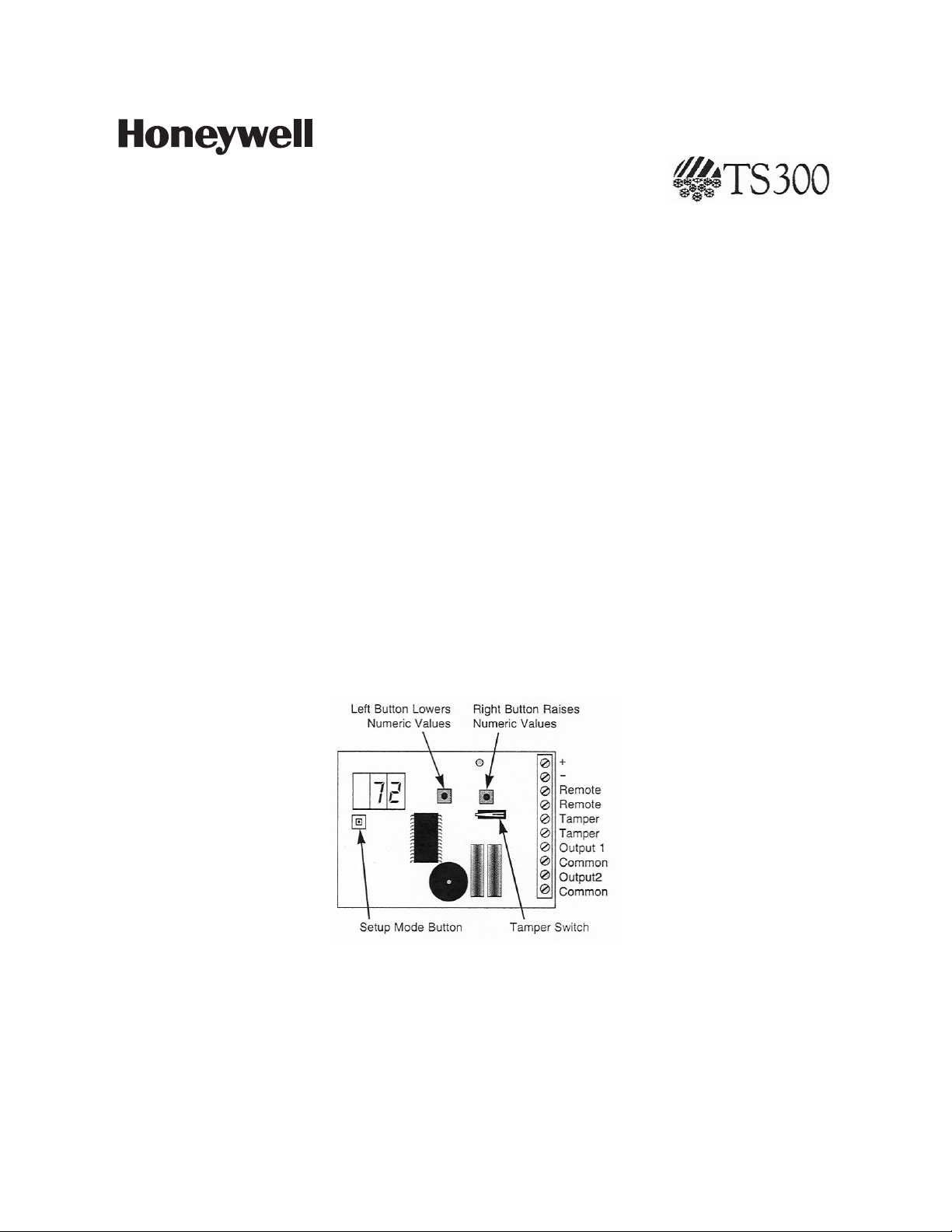
Illustration A
SETUP PROCEDURE
Remove the front cover from the TS300. With power applied to the unit, press the SETUP MODE switch (see Illustration
A). Press the Left button to lower a numeric limit by a value of one (press and hold to decrement by tens); Press the right
button in raise a numeric limit by a value of one (press and hold to increment by tens). Pressing either button will toggle
the either/or choices. When your preferred setting is displayed, press the setup button to accept and move to the next
parameter.
Note that, when setting High/Low limits in Centigrade mode, incrementing/decrementing will raise/lower the limit by the
equivalent of 1° Fahrenheit (or 10° F, if button is pressed and held).
Page 2
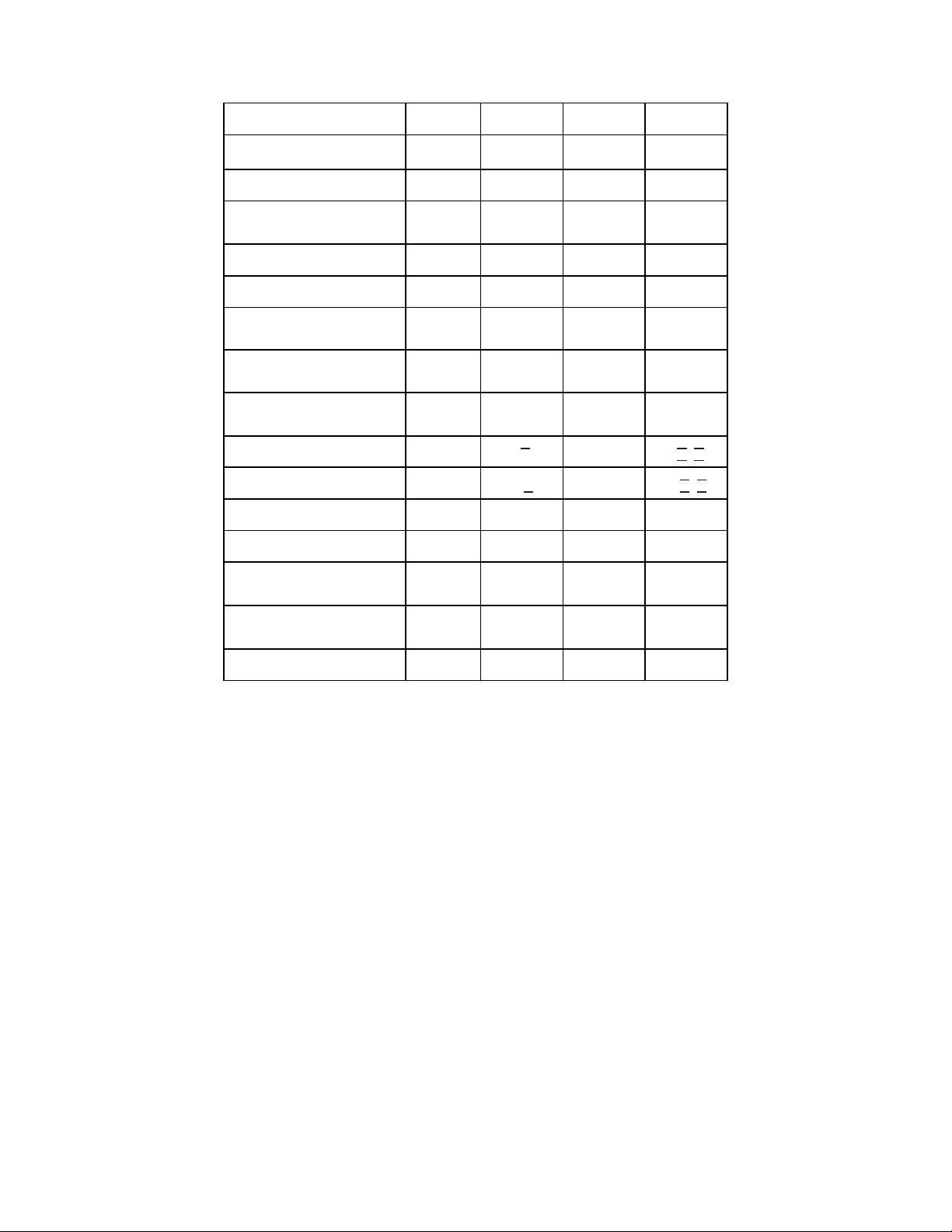
Table 1. Programmable Parameters
F F
0 0
0 0
0 0
0 0
Parameter
Fahrenheit or Centigrade
Remote Probe Enable
Display Local or Remote
temperature
Set Local Sensor Low Limit
Set Local Sensor High Limit
Set Remote Probe Low Limit
Set Remote Probe High Limit
Select Output Mode (both
relays)
Set Output Map for Output 1
Set Output Map for Output 2
Set Alarm Delay for Output 1
Set Alarm Delay for Output 2
1
2
2
Display
F-C
rEN
DSP
LLO
LHI
RLO
RHI
Out
OuI
Ou2
DLI
dL2
Default
NO
LCL
40
I40
40
I40
NC
I
2
Min
Max
C
NO
LCL
32
32
-40
-40
NC
I
2
I
2
YES
RPR
I40
I40
I40
I40
NO
255
255
Enable Alarm Audible
Annunciator
Audible Alarm Silence
Timeout
Hysteresis
3
Degrees of
AUD
SIL
HYS
YES
NO
YES
255
I0
NOTES:
1
If programmed for Normally Closed (NC) it is supervised, if Normally Open (NO) it is unsupervised.
2
The Output map is a graphical representation of the possible choices.
The left character indicates which relay you are mapping, 1 or 2.
The middle character is the local sensor map and the right character is the remote probe map. See Table 2 for
map designations.
3
Hysteresis provides a buffer so that temperature that is shifting back and forth around the alarm limit point will
not create multiple alarms. You set the # of degrees that the temperature will have to rise above the
temperature low limit set point or drop below the high limit set point for the alarm to turn off. For example, if
you set the HYS at 3 degrees and your low limit is 40 degrees, you will go into an alarm condition when the
temperature reaches 39 degrees and restore from alarm would not occur until the temperature rose to 43
degrees. Hysteresis is limited to ½ the difference in degrees between the low temperature limit and high
temperature limit or the programmed HYS setting (max of 10E) whichever is least.
4
The setup will NOT be lost in the event that power is lost at the panel.
5
Options that relate to the remote probe will only appear is you have enabled the remote probe in selection 2
of the table parameters.
6
High/Low limits shown in table are degrees Fahrenheit. Equivalent Centigrade temperatures apply when
Centigrade has been selected.
7
Hysteresis is always programmed in degrees Fahrenheit, even if Centigrade has been selected to set limits.
-2-
Page 3

Table 2. Output Map Designations
I
Output 1 - not used
I
Output 1 - Local and Remote Low
Alarms
I
I
I
I
I
I
Output 1 - Local Low Alarm
Output 1 - Local High Alarm
Output 1 - Local Low and High
Alarms
Output 1 - Remote Low Alarm
Output 1 - Remote High Alarm
Output 1 - Remote Low and
High Alarms
I
I
I
I
I
I
Output 1 - Local Low and Remote
High Alarms
Output 1 - Local Low and Remote
Low and High Alarms
Output 1 - Local High and Remote
Low Alarms
Output 1 - Local and Remote High
Alarms
Output 1 - Local High and Remote
Low and High Alarms
Output 1 - All Alarms; Local Low
and High and Remote Low and
High
Map designations:
Low Limit High Limit Both Low
& High Limits
Examples: (The same choices can be used for relay 2)
OPERATION
Display - The TS300 displays the selected temperature (local [ambient] or remote) in either Fahrenheit or
Centigrade as programmed. To check the temperature at a sensor, press the left button for the local sensor or
the right button for the remote probe. The temperature you have requested will flash 5 times and then return to
displaying the temperature of the sensor you have chosen to display.
Alarm - If the temperature at an enabled sensor varies outside either of its mapped limits, the audible
annunciator will sound, if programmed, and the mapped output will switch to its alarm state, but only after the
selected delay time has expired. If the delay time is set to 0 the alarm will be immediate. The maximum delay
time is 255 minutes (4 hours, 15 minutes). The output will remain in its alarm state until the temperature
returns to within the selected limits as buffered by the programmed degrees of hysteresis. As long as the
temperature remains outside the selected temperature limits, the display will cycle between the desired display
temperature and the name of the limit(s) exceeded.
Silence - The Audible alarm is silenced by pressing either of the buttons. It will remain silenced until the
silence timeout time expires and then it will become audible again. In addition, when the output delay time is in
the final 60 seconds the audible will switch to a fast beep (250mS pulsed), if it has been enabled.
High and Low Temp limits and Alarm Memory - To display the programmed high and low temperature
limits, press and hold both buttons momentarily. The unit will show the programmed limits followed by any
alarms in alarm memory. The TS300 stores the last 8 alarm events. An alarm event is one where the relay
output was activated. If delays are used, and the temperature restored before the delay time expired, it is not
considered an alarm and will not be stored in alarm memory. Alarms are displayed as the limit that was
violated. For example LLO for local low limit. The alarms are displayed most recent to oldest. Alarm memory is
cleared when you enter set-up mode or when power is cycled to the unit.
-3-
Page 4

e, Suite 100
TS300 SPECIFICATIONS
TS300 SPECIFICATIONS
Temperature Range / Accuracy (Local Sensor)
Temperature Range / Accuracy (Remote Probe)
Minimum Span between Hi and Low Limits
Alarm Delay
Alarm Output Type
Alarm Output Resistance
Alarm Output Rating
Audible Alarm
Audible Alarm Silencing
Input Voltage
Input Current
Case Dimensions
T280R REMOTE TEMPERATURE PROBE
(purchased separately)
The T280R is a Remote Temperature Probe for use with the TS300. The Remote Probe is a sealed temperature sensor
with 15 feet of two conductor, 24 AWG stranded cable. The cable should be connected to the two terminals labeled
REMOTE. (Polarity need not be considered.)
Caution: Excessive force applied to the probe may damage the device.
T280R Remote Probe Specifications
Chemical Properties
Max. Compression Force Applied to Probe
Max. Tensile Force Applied Between
Probe and Cable
Max. Cable Length
• The T280R may be extended from 15' up to 300' using shielded 24 AWG cable. Insure the shield is grounded for noise immunity.
For the latest warranty information, please go to:
http://www.security.honeywell.com/hsc/resources/wa/index.html
CE compliance
logo. This product
is in conformity
with the relevant
European union
harmonization
legislation
The WEEE
symbol. It
indicates this
product is to be
recycling and not
been thrown
away in a
dustbin.
Logo de
conformité CE.
Ce produit est
conforme à la
législation
d’harmonisation
dans l’Union
européenne
pertinente
Le symbole
DEEE. Il indique
que ce produit
doit être recyclé
et qu’il ne doit
pas être jeté à la
poubelle.
CE‐Richtlinien‐L
ogo. Dieses
Produkt stimmt
mit den
relevanten
Harmonisierungs
gesetzen der EU
überein
Das
WEEE‐Symbol.
Es bedeutet,
dass dieses
Produkt
recyclebar ist
und nicht in den
Hausmüll gehört
Logotipo de
cumplimiento de
CE. Este
producto cumple
con la
legislación de
uniformidad de la
Unión Europea
pertinente
Símbolo WEEE
Indica que este
producto es para
reciclar y que no
se debe arrojar
al cubo de
basura
Indica che questo
essere riciclato e
ÊN8188-2V3DŠ
N8188-2V3 11/08 Rev. B
2 Corporate Center Driv
P.O. Box 9040, Melville, NY 11747
Copyright 2008
Honeywell International Inc.
32°F to 140°F (0°C to 60°C) "3°F ("1.7°C)
-40°F to 140°F (-40°C to 60°C) "4°F ("2.2°C)
4°F (2.2°C)
0 - 255 minutes in 1 min increments
(2) Form A reed relays
25 ohms maximum
50 mA max. @ 30 VDC
4 kHz, 75 dB @ 10 cm pulsed 750 mS on/off
0 - 255 minutes in 1 min increments
7 to 16 VDC
25 mA (max.)
4" x 2.6" x 0.9" (10.2 cm x 6.6 cm x 2.3 cm
Non-corrosive Water Resistant
10 lb. force
5 lb. force
300 feet*
Logo conformità
CE. Questo
prodotto è
conforme alla
legislazione
armonizzata
pertinente
dell'Unione
Europea
Simbolo RAEE.
prodotto deve
non può essere
gettato nel
secchio della
spazzatura
CE logo shody.
Tento výrobek je v
souladu s
příslušnými
právními předpisy
Evropské unie pro
harmonizaci
Symbol WEEE.
To označuje, že
tento výrobek má
být recyklován a
ne být vyhozen do
popelnice.
CE uygunluk
logosu. Bu ürün,
ilgili Avrupa Birliği
uyumlaştırma
mevzuatına
uygundur
WEEE sembolü.
Bu ürüne geri
dönüşüm
yapılması
gerektiğini ve çöp
kutusuna
atılmaması
gerektiğini belirtir.
Symbol zgodności
CE. Produkt jest
prawodawstwa
harmonizacyjnego
Symbol WEEE.
produkt należy
recyklingowi i nie
można wyrzucać
go do pojemników
zgodny z
właściwymi
przepisami
unijnego
Oznacza, że
poddać
na śmieci.
 Loading...