

Page 1
62-0271-07
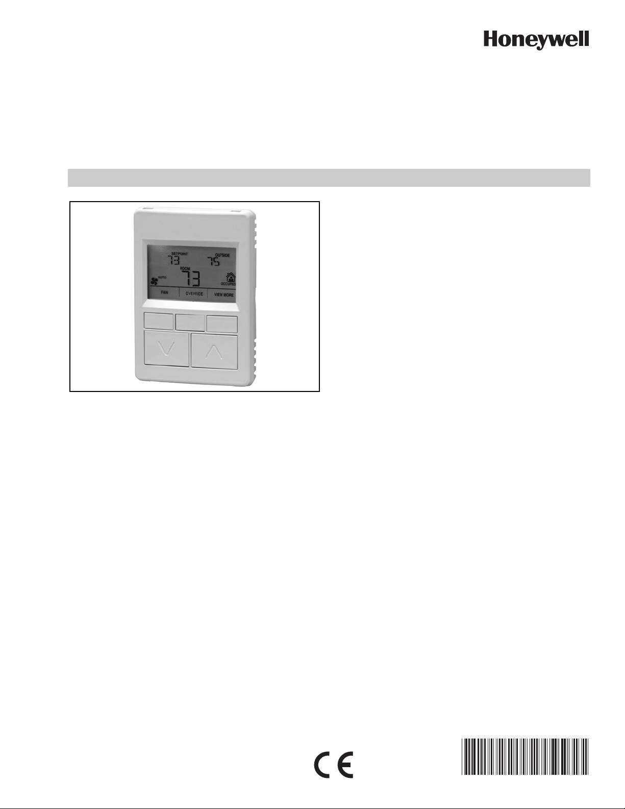
Zio®/Zio Plus LCD Wall Modules
TR70, TR71 and TR75 models with Sylk® bus
INSTALLATION INSTRUCTIONS
• Customized parameter access, by using the WEBs-AX
Workbench tool.
• Ability to link setpoint limits to a network variable.
• Programmable for: home screen options, tenant
access, contractor access, access to controller
parameters, setpoint, override, fan, and other
parameters.
• TR70 and TR71 have the ability to access and adjust
virtually any parameter in the programmable controller
(except Scheduling).
• TR75 can additionally access and adjust the controller
schedule.
• The TR71 has roughly twice the memory capacity for
parameters as the TR70, and the TR75 has more than
twice the memory capacity for parameters as the TR71.
• Ability to balance the VAV system from the wall module.
• Home screen can display one to three of any of the
PRODUCT DESCRIPTION
The TR70, TR71 and TR75 are 2-wire, non-polarity sensitive,
Sylk bus communicating wall modules, which communicate
with Spyder® and some ComfortPoint™ programmable
controllers.
All models have a space-temperature sensor, network bus
jack, and an LCD panel with three softkeys and two Up/Down
adjustment keys. The TR70-H, TR71-H and TR75-H models
include an onboard humidity sensor.
NOTES:
1. Refer to the Zio/Zio Plus LCD Wall Modules –
Specification Data, form 63-1322, for specific
model features and additional information.
2. Refer to the Zio/Zio Plus LCD Wall Modules –
Operating Guide (Form 63-2719) for information
about customizing the wall module configuration,
such as modifying the default Home screens or
creating your own application.
FEATURES
The Zio wall modules include:
• Ability to control user access to controller parameters,
including password protection on TR71 and TR75
models.
• Ability to assign labels for enumerated values.
following parameters: temperature setpoint, room
temperature, room humidity, outdoor humidity,
outdoor temperature, and time, or one of virtually any
parameter in the controller.
•Network bus jack.
• Simple 2-wire terminal connection to the
programmable controller and an optional 2-wire
terminal connection for the network. All connections
are polarity insensitive.
• Permanent retention of user configuration, including
setpoints after a power outage.
SPECIFICATIONS
Models: TR70, TR71, TR75.
TR70-H, TR71-H and TR75-H include an onboard
humidity sensor.
Environmental Ratings:
• Operating Temperature: 30°F to 110°F (-1°C to 43°C)
• Shipping Temperature: -40°F to 150°F (-40°C to 65.5°C)
• Relative Humidity: 5% to 95% non-condensing
Accessories:
50007298-001 (pack of 12) medium, cover plate;
6-7/8 x 5 in. (175 x 127 mm).
Approvals:
Class B
CE; UL94-HB plastic enclosure; FCC Part 15,
Page 2
ZIO®/ZIO PLUS LCD WALL MODULES
CAUTION
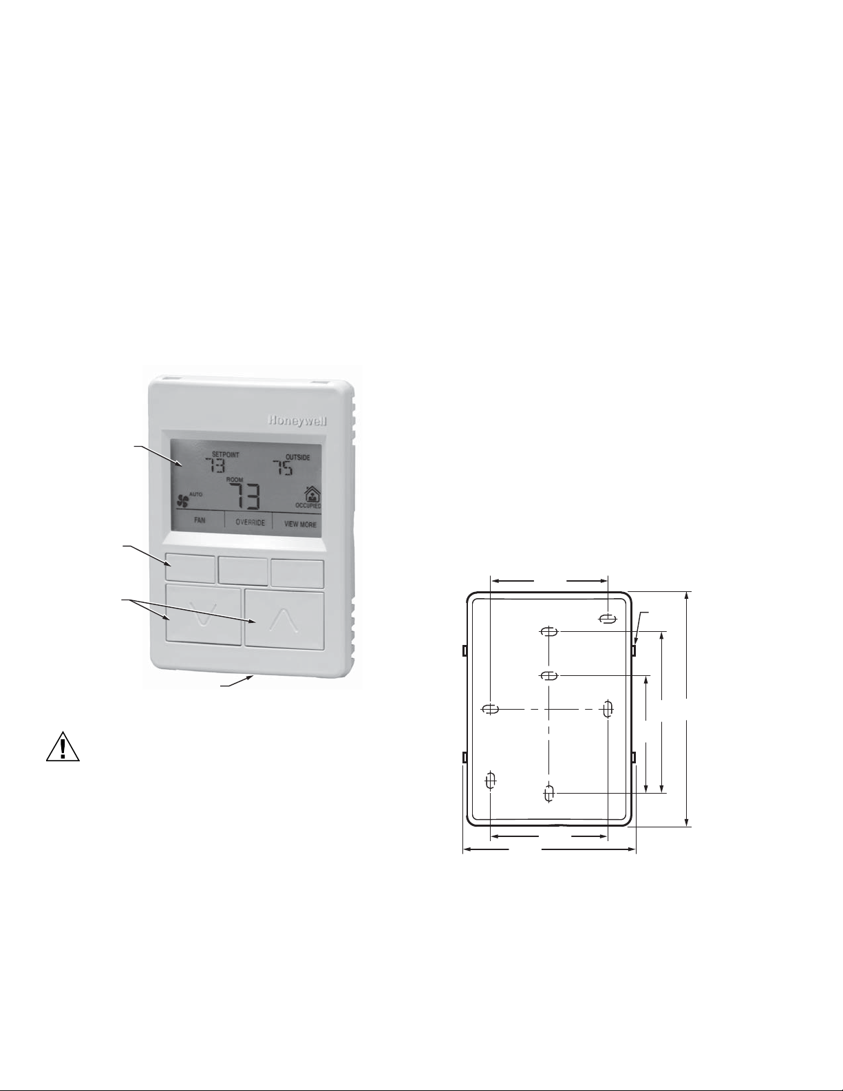
LCD PANEL
M27344
SOFTKEYS (3)
UP/DOWN
ARROW KEYS
NETWORK BUS PORT (ON BOTTOM OF CASE)
2-3/8 (60)
2-3/8
(60)
3-1/4
(83)
M27345
LOCKING
TAB S (4 )
2-3/8 (60)
3-3/8 (95)
4-1/8
(105)
Communications
The wall modules use a sensor bus (S-BUS) for
communications with the programmable controller. Wire the
two S-BUS terminals according to these installation
instructions.
The wall modules have a network bus port for L
ONMARK® or
BACnet® communications. If network communication is
needed, connect the building LON network wires to the two
terminals (NET-1 and NET-2), according to these installation
instructions. A network bus port is accessible at the bottom of
the wall module by removing the jack plug. See Fig. 1.
The network bus and S-BUS terminals (see Fig. 6 on page 4)
are insensitive to polarity, minimizing installation errors due to
mis-wiring.
BEFORE INSTALLATION
IMPORTANT
All wiring must comply with local electrical codes and
ordinances or as specified on installation wiring diagrams.
— Wall module wiring can be sized from 18 to 24 AWG (0.82
to 0.20 sq. mm), depending on the application. For
multiple Zios on the same S-BUS, 24 AWG wire is
recommended.
— For S-BUS wiring, the Zio may be mounted up to 200 ft.
(61 m) from the programmable controller. If multiple Zios
are installed, the total distance from the controller to the
last Zio should not exceed 200 ft.
— Twisted pair wire is recommended for wire runs longer than
100 ft. (30.5 m).
— All wiring is polarity insensitive.
— The cover for the wall module is packed separately from
the subbase for ease of installation.
INSTALLATION
Mount the wall module on an inside wall approximately 54 in.
(1372 mm) from the floor (or in the specified location), to allow
exposure to the average zone temperature. Do not mount the
wall module on an outside wall, on a wall containing water
pipes, or near air ducts. Avoid locations that are exposed to
discharge air from registers or radiation from appliances,
lights, or the sun.
Fig. 1. LCD Wall Module features.
Erratic System Operation Hazard.
Failure to follow proper wiring practices can
introduce disruptive electrical interference (noise).
Keep wiring at least one foot away from large inductive
loads such as motors line starters, lighting ballasts,
and large power distribution panels.
Shielded cable is required in installations where these
guidelines cannot be met.
Ground the shield only to the grounded controller
case.
The wall module can be mounted on a wall, on a standard
utility conduit box using No. 6 (3.5 mm) screws or on a 60 mm
wall outlet box (see Fig. 3). When mounting directly on a wall,
use the type of screws appropriate for the wall material.
Fig. 2. Subbase mounting holes and locking tabs.
62-0271—07 2
Page 3

Fig. 3. Mounting on standard utility conduit box or
CAUTION
M27346
STANDARD UTILITY
CONDUIT BOX
SUBBASE
NO. 6 SCREW
60 mm WALL
OUTLET BOX
SUBBASE
3.5 mm SCREW
WALL MODULE
WALL
MODULE
60 mm wall outlet box.
ZIO®/ZIO PLUS LCD WALL MODULES
Improper Electrical Contact Hazard.
Screw-type terminal blocks are designed to accept
no more than one 18 AWG (0.82 sq. mm)
conductor.
Connect multiple wires that are 18 AWG (0.82 sq. mm)
with a wire nut. Include a pigtail with this wire group
and attach the pigtail to the individual terminal block.
Wiring Wall Modules
Wire the terminal block shown in Fig. 6 as follows:
1. For single wires, strip 3/16 in. (5 mm); for multiple wires
going into one terminal, strip 1/2 in. (13 mm) insulation
from the conductor. See Fig. 5 for wiring multiple Zios.
2. Insert the wire in the required terminal location and
tighten the screw to complete the termination.
3. Review and verify the terminal connection wiring
illustrated in Fig. 6.
NOTE: The recommended wire size for the network bus
and S-BUS is Level IV, 22 AWG (0.34 sq. mm) plenum or non-plenum rated, unshielded, twisted
pair, solid conductor wire. However, larger gauge
standard thermostat wiring will also work for
runs up to 100 feet.
3 5/16 (84)
4 5/8
(117)
15/16
(24)
M27347
Fig. 4. LCD Wall Module dimensions in inches (mm).
Wiring
The LCD wall module is shipped with its mounting plate
(subbase) separate from the module. All terminal connections
can be made to the backside of the module. There are no field
adjustable/replaceable components inside the module.
Attach the wires from the programmable controller and
network to the appropriate wall module terminals, as indicated
in Fig. 6 on page 4.
TWO WIRES INTO ONE TERMINAL
1.
1/2
(13)
DAISY-CHAINING MULTIPLE ZIOS HOME RUNNING MULTIPLE ZIOS
MAX WIRE RUN FROM SPYDER
TO FARTHEST ZIO IS 200FT.
STRIP 1/2 IN.
(13MM) FROM
WIRES TO BE
ATTACHED AT
ONE TERMINAL.
2.
TWIST WIRES
TOGETHER
WITH PLIERS
(A MINIMUM OF
THREE TURNS).
TO SPYDER
TO ZIO
WALL MODULE
TERMINALS
3.
CUT TWISTED END OF WIRES TO
3/16 IN. (5 MM) BEFORE INSERTING
INTO TERMINAL AND TIGHTENING
SCREW. THEN PULL ON EACH WIRE
IN ALL TERMINALS TO CHECK FOR
GOOD MECHANICAL CONNECTION.
TO SPYDER
MAX WIRE RUN FOR EACH
HOME RUN IS 200FT.
M27348
Fig. 5. Options for Wiring Multiple Zios.
3 62-0271—07
Page 4

ZIO®/ZIO PLUS LCD WALL MODULES
M27349
SLOTS FOR SUBBASE
LOCKING TABS (X4)
0
1
2
3
4
9
8
7
6
5
WALL MODULE BUS
ADDRESS DIAL
(DEFAULT SETTING = 1)
S-BUS PROGRAMMABLE
CONTROLLER CONNECTION
NETWORK BUS
CONNECTION
EACH OF T HE TWO WIRE CONNECTI ONS FOR THE S- BUS AND NETWORK
BUS TERM INALS ARE PO LARITY IN SENSITIVE.
1 2 3 4
1
1
50028668-XXX
4321
S-BUS
S-BUS
NET-2
(optional)
NET-1
(optional)
TR70-H
YY WK
HONEYWELL
PATENT PENDING
GOLDEN VALLEY,MN
ASSEMBLED IN MEXICO
WALL
PULL THE
SCREWDRIVER
TOWARD YOU
M27350
M27351A
Fig. 6. Terminal connections, Wall Module bus address
dial, and TR70-H address dial (rear view of LCD wall
module).
Setting the Wall Module Bus Address Dial
For the TR70, ensure that the wall module bus address dial is
set to 1. For the TR71 or TR75 models, set the address to any
number from 0 to 9. (A setting of 0 on Zio is equal to 10 in the
Configuration Tool, so if the Zio is set to 0, set the address to
10 in the Configuration Tool.) Address must be different for
each device on the Sylk bus. Use a thin blade screwdriver to
turn the dial arrow. The address on the wall module must
match the address in the tool. A maximum of four Zios may
be wired on a single Sylk bus, with no more than one TR70
per bus.
Attaching the Wall Module to the Subbase
When all wiring is complete, press the LCD wall module
straight down onto the subbase until it snaps into place.
Removing the Wall Module from Subbase
To remove the wall module from its subbase:
1. Insert a thin, flat-blade screwdriver into the slot on the
right side of the wall module (see Fig. 7).
2. Pull the screwdriver toward you to release the right side
of the wall module from the subbase.
3. Pull the wall module out and away from the subbase.
Fig. 7. Removing Wall Module from Subbase.
POWER UP
After the wall module is properly wired to the controller, it will
power up. Upon initial power up, the wall module LCD panel
displays the phrase, “PLEASE LOAd” (see Fig. 8). This
phrase alternates with bus address, model and version
number (TR71 and TR75 only), and any onboard sensor
display, such as temperature, humidity, etc.
Refer to the Zio/Zio Plus LCD Wall Modules Operating Guide
(Form 63-2719) to configure and load the desired user
interface and parameters into the wall module.
Fig. 8. Wall Module LCD display at initial power up.
ComfortPoint™ is a trademark of Honeywell International Inc.
L
ONMARK® is a trademark of the LonMark Association.
BACnet® is a trademark of BACnet International.
Sylk® is a trademark of Honeywell International Inc.
Zio® is a trademark of Honeywell International Inc.
Automation and Control Solutions
Honeywell International Inc.
1985 Douglas Drive North
Golden Valley, MN 55422
customer.honeywell.com
® U.S. Registered Trademark
© 2012 Honeywell International Inc.
62-0271—07 M.S. Rev. 01-12
Printed in United States
 Loading...