

63-1322-02
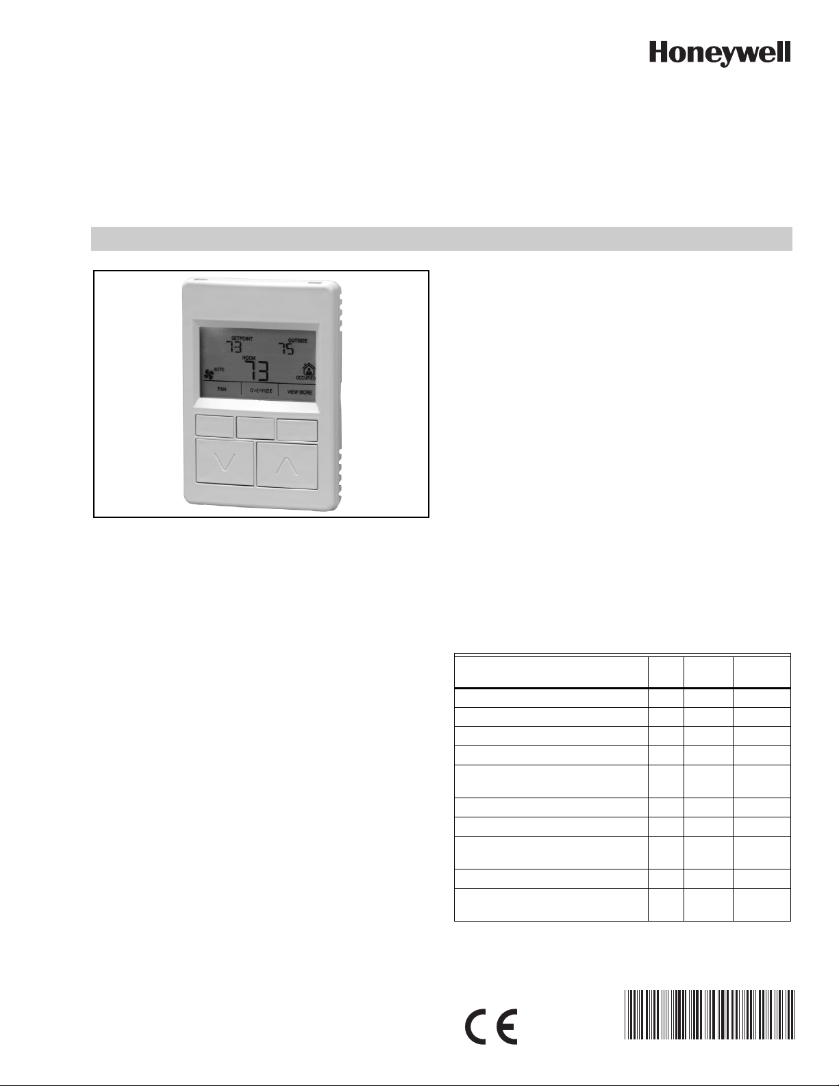
Zio®/Zio Plus LCD Wall Modules
TR70, TR71, TR75 WITH Sylk® Bus
SPECIFICATION DATA
• Programmable for: Home screen options, tenant
access, contractor access, optional password
protection to contractor mode, access to controller
parameters, setpoint, override, fan, and other
parameters.
• Ability to access and adjust most parameters in the
programmable controller.
• TR75 can access and adjust the controller schedule.
• Ability to balance the VAV system from the wall
module.
• Home screen can display one to three of any of the
following parameters: Temperature Setpoint, Room
Temperature, Room Humidity, Outdoor Humidity,
Outdoor Temperature, and Time, or one of virtually any
parameter in the controller.
•Network bus jack.
• Simple 2-wire terminal connection to the
programmable controller (includes power) and an
GENERAL
The TR70 Series Zio (TR70/TR70-H, TR71/TR71-H) and Zio
Plus (TR75/TR75-H) are 2-wire, non-polarity sensitive, Sylk
bus communicating wall modules for use with Spyder® and
ComfortPoint™ programmable controllers.
All models have a space-temperature sensor, network bus
jack, and an LCD panel with three softkeys and two Up/Down
adjustment keys. The TR7-H, TR71-H and TR75-H models
include an onboard humidity sensor.
NOTE: Refer to the Zio/Zio Plus LCD Wall Modules Oper-
ating Guide (form 63-2719) for information about
customizing the wall module configuration in the
WEBs-AX Workbench, such as modifying the
default Home screens or creating your own application.
FEATURES
The TR70 Series wall modules include:
• Ability to control tenant access to controller
parameters via password protection.
• Ability to assign labels for enumerated values.
• Customized parameter access, by using the Honeywell
WEBs-AX Workbench tool.
• Ability to link setpoint limits to a network variable.
optional 2-wire terminal connection for the network. All
connections are polarity insensitive.
• Permanent retention of user configuration, including
setpoints after a power outage.
Table 1. TR70 Series Features.
Zio
Features
Scheduling x
Parameter Memory (bytes) 1K 2K 4.9K
Up to four Zios on Sylk x* x x
Enumerated Values x x
Setpoint Limits as NVs – linking
now possible
System and Fan command as NVs x x
Password protection x x
Firmware version/model visible on
display
0.5 and 5 value increments x x
"-" and "/" characters in parameter
names
* Support for up to four TR71 and/or TR75s per Spyder, and if
a TR70 is present, a maximum of three Zios (any combination of models) are allowed.
TR70
Zio
TR71
xx
xx
xx
Zio Plus
TR75
ZIO®/ZIO PLUS LCD WALL MODULES
3 5/16 (84)
4 5/8
(117)
15/16
(24)
M27347
SPECIFICATIONS
Compatibility: Full feature set, including scheduling and
password protection requires the latest Spyder firmware
(field upgradeable with Spyder Flash Tool), Spyder Tool
version greater than 5.18, and WEBs-AX Workbench version 3.4.57 or greater.
Construction: Two-piece construction, cover and internally
wired subbase. Field wiring, 18 to 24 AWG (0.82 to 0.20
sq. mm), connects to a terminal block in the subbase.
Mounting Options: The LCD wall modules can be mounted
on a standard two by four inch junction box or on a 60 mm
diameter junction box. The modules may be mounted up to
200 ft. (61 m) from the programmable controller. Twisted
pair wiring is recommended for distances longer than 100
ft. (30.5 m).
Dimensions (H/W/D): See Fig. 2 on page 2.
Environmental Ratings:
Operating Temperature: 30°F to 110°F (-1°C to 43°C)
Shipping Temperature: -40°F to 150°F (-40°C to 65.5°C)
Relative Humidity: 5% to 95% non-condensing
Temperature Setpoint Range: Default range is 55°F to 85°F
(10°C to 35°C); configurable for other ranges.
Temperature Sensor Accuracy: ±0.36°F at 77°F (±0.2°C at
25°C)
Humidity Sensor Accuracy (TR71-H/TR75-H only): ±5%
RH from 20% to 80% RH
Power: 18 Vdc power is supplied to the wall module from the
2-wire S-BUS connection to the programmable
controller.
Accessories: 50007298-001 (pack of 12) medium, cover
plate; 6-7/8 x 5 in. (175 x 127 mm).
Approvals:
Class B
CE; UL94-HB plastic enclosure; FCC Part 15,
NET-2
(optional)
S-BUS
4321
S-BUS
HONEYWELL
PATENT PENDING
GOLDEN VALLEY,MN
ASSEMBLED IN MEXICO
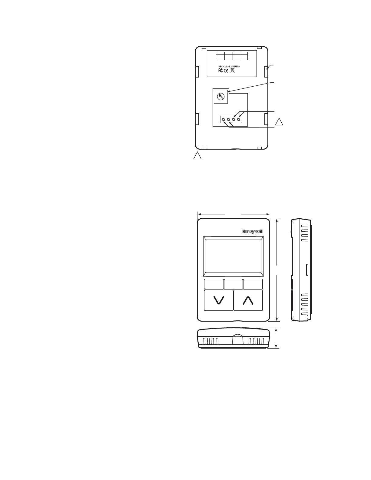
SLOTS FOR SUBBASE
LOCKING TABS (X4)
WALL MODULE BUS
ADDRESS DIAL
(DEFAULT SETTING = 1)
S-BUS PROGRAMMABLE
CONTROLLER CONNECTION
1
NETWORK BUS
CONNECTION
M27349
NET-1
(optional)
TR70-H
YY WK
50028668-XXX
2
1
3
0
4
9
5
6
8
7
1 2 3 4
EACH OF T HE TWO WIRE CO NNECTI ONS FOR THE S- BUS AND NET WORK
1
BUS TERM INALS ARE PO LARITY IN SENSITIVE.
Fig. 1. LCD wall module components (rear view).
NOTE: 18 Vdc power for the LCD wall modules is sup-
plied from the programmable controller.
Module Dimensions
Terminal Wiring Location
Fig. 1 illustrates the location of the terminal block and other
features on the TR70 Series wall modules.
63-1322—02 2
Fig. 2. Wall module dimensions in inches (mm).
Communications
The wall modules use a sensor bus (S-BUS) for
communications with the programmable controller.
For network communication, the building’s LON or BACnet®
network wires connect to the two terminals (NET-1 and NET-
2). See Fig. 1. A network bus port is accessible at the bottom
of the wall module by removing the jack plug.
The network bus and S-BUS terminals (see Fig. 1) are
insensitive to polarity, minimizing installation errors due to
mis-wiring. The recommended wire size for the network bus
 Loading...