

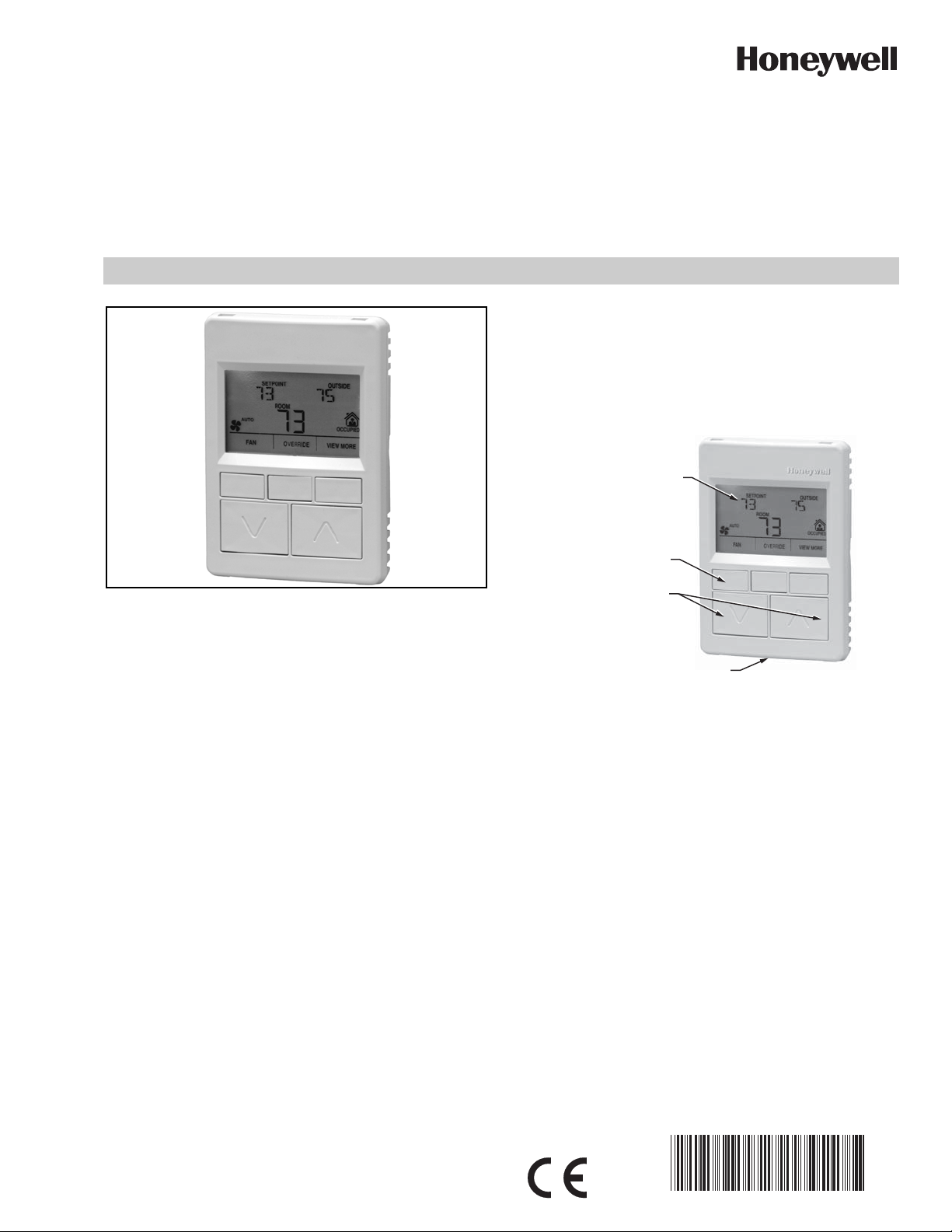
Zio®/Zio Plus LCD Wall Modules
LCD PANEL
M27344
SOFTKEYS (3)
UP/DOWN
ARROW KEYS
NETWORK BUS PORT (ON BOTTOM OF CASE)
TR70, TR71, TR75 with Sylk® Bus
OPERATING GUIDE
begins with “Initial Power-Up” on page 2, and the general
overview begins with “Operating the Zio Wall Module” on
page 19.
It is intended to guide you through the features and operation
of the TR70 Series as you interface with the programmable
controller and establish pre-programmed or custom
configurations.
APPLICATION
The Zio TR70 Series (TR70, TR70-H, TR71, TR71-H, TR75,
and TR75-H OS numbers) LCD Wall Modules provide an
operator interface for monitoring and adjusting parameters in
the wall module itself and in the programmable controller
(refer to the
or the
form 63-2663, depending on the programmable controller
used) to which it is wired. The wall module may be customized
and supports both a contractor and a tenant user interface.
NOTE: This document illustrates the wall module configura-
The wall module has a snap in mounting to a subbase that
may be mounted on a wall, on a standard utility conduit box, or
on a 60 mm wall outlet box. Wiring connections to the wall
module are made through a cutout in the back of the wall
module.
All models have a space temperature sensor, network bus
jack, and an LCD panel with three softkeys and two Up/Down
adjustment keys. Models with -H also include an onboard
humidity sensor.
Honeywell Spyder® User’s Guide,
form 63-2662,
ComfortPoint™ Programmable Controller User’s Guide,
tion process using information from the
Spyder User’s Guide
(form 63-2662).
Honeywell
PREFACE
This Operating Guide is intended to provide configuration
information (using the Niagara Workbench tool) and a general
overview of the TR70 Series operator interface. Configuration
Fig. 1. LCD Wall Module features.
Contents
Application ........................................................................ 1
Preface ............................................................................. 1
TR70 Series Features ....................................................... 2
Compatibility ............................................................. 2
Initial Power-Up ................................................................. 2
Setup and Configuration ................................................... 3
Initial Setup and Configuration .................................. 3
Selecting the Wall Module ......................................... 3
TR71/TR75 Labels .................................................... 3
Navigation and Memory Usage ................................. 3
Wall Module Configuration ........................................ 4
General Settings ................................................... 5
Categories and Parameters .................................. 5
Home Screen Options ........................................... 9
Occupancy and Override ...................................... 10
Fan Command ....................................................... 12
System Status and Command .............................. 13
Schedule/Time ...................................................... 14
Password ............................................................... 15
Preview .................................................................. 16
Completing the Setup and Configuration .................. 17
Operating the Zio Wall Module ......................................... 19
Contractor Mode Operation ...................................... 19
Tenant Mode Operation ............................................ 22
63-2719-03
ZIO®/ZIO PLUS LCD WALL MODULES
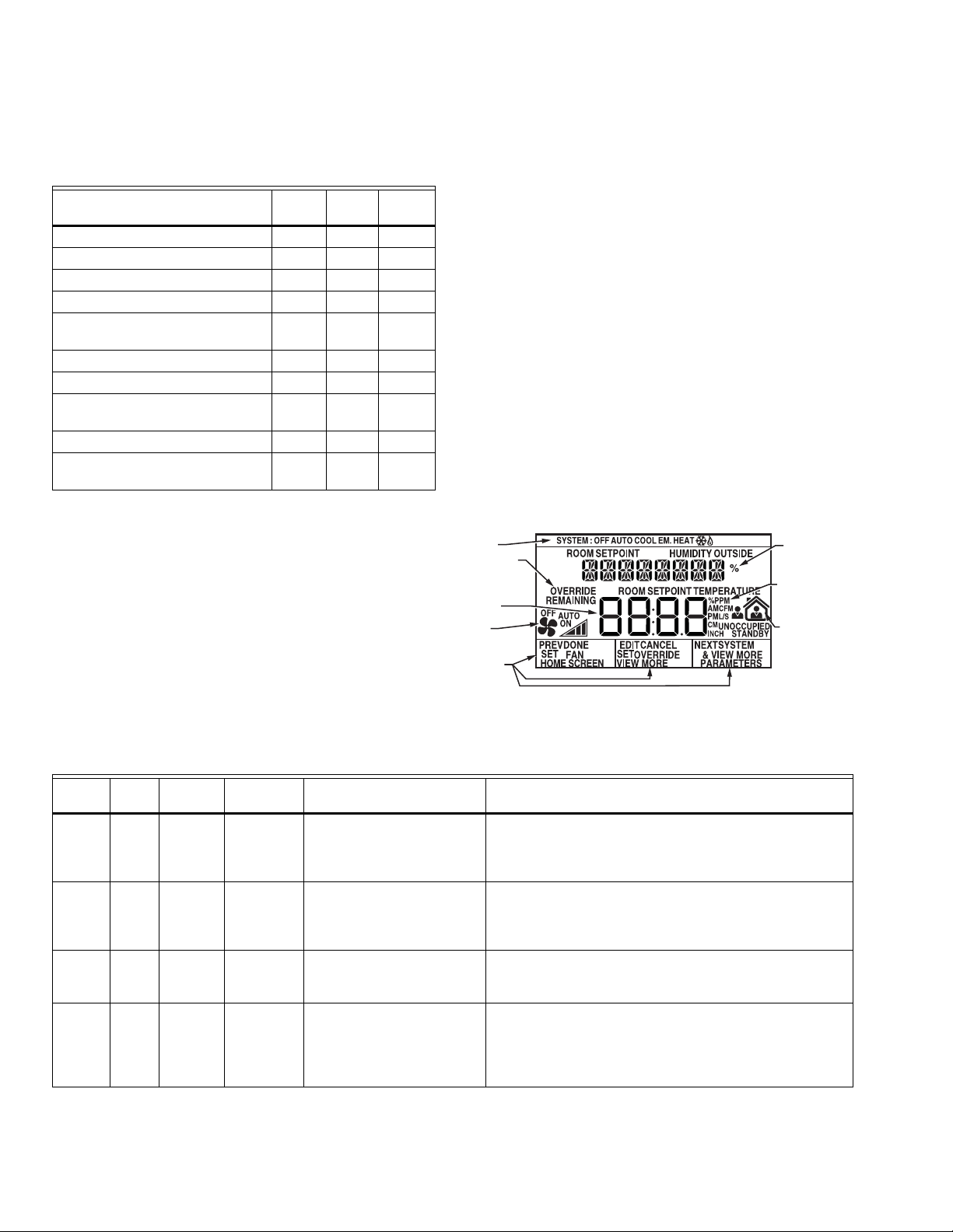
SYSTEM
STATUS
AREA
FAN
INFORMATION
SOFTKEY
LABELS
LABEL/
VALUE
(8 CHAR.)
CURRENT
DISPLAYED
VALUE
OCCUPANCY
STATUS
ENGINEERING
UNITS
OVERRIDE
INFORMATION
M27353
TR70 SERIES FEATURES
Table 1. TR70 Series Features.
Features
TR70
Scheduling x
Parameter Memory (bytes) 1K 2K 4.9K
Up to four Zios on Sylk x* x x
Enumerated Values x x
Setpoint Limits as NVs – linking
now possible
System and Fan command as NVs x x
Password protection x x
Firmware version/model visible on
display
0.5 and 5 value increments x x
"-" and "/" characters in parameter
names
* A maximum of four Zios may be wired on a single Sylk bus,
with no more than one TR70 per bus.
Compatibility
The TR70 Series LCD Wall Modules operate with the Sylk
Enhanced Spyder Controller or the Sylk Enhanced
ComfortPoint Controller. The table below provides
compatibility information for each model. The TR71/TR75 can
replace a TR70 in an installation where an upgrade to WEBsAX or Spyder or reprogramming is not desired. Features like
scheduling, additional memory, etc. will not be available.
Zio
Zio
Zio Plus
TR71
TR75
xx
xx
xx
Likewise, a TR71 can be replaced by another TR71 or TR75
without reprogramming required. A TR75 can only be
replaced with a TR75 where no reprogramming is desired.
INITIAL POWER-UP
IMPORTANT
1. Make sure the TR70 Series wall module is properly
mounted and properly wired and connected to the
programmable controller.
2. Refer to the Zio™ LCD Wall Modules TR70 Series
with Sylk™ Bus – Installation Instructions, form 620271, for specific installation requirements.
Upon initial power-up before configuring the wall module, the
LCD screen displays the phrase “PLEASE LOAd” in the Label/
Value area of Fig. 2. This phrase alternates with any onboard
sensor display such as temperature. The TR71/TR75 also
display the firmware revision number, model number and Sylk
bus address as shown in Fig. 27.
Fig. 2 illustrates all the possible LCD Wall Module display
elements. Only those elements pertinent to the current
configuration and status actually display.
Fig. 2. TR70 Series Wall Module - LCD screen.
Table 2. Compatibility.*
ScenarioSpyde
r Tool
1 5.200+Latest YES New TR71/75 functionality
Spyder
Firmware
Compatible
? Zio TR70/TR71/TR75* What can be done?
Ideal scenario
available (if TR70 is present,
then only TR70
functionality)
2 5.200+Old YES Only with TR70 functionality
(TR71/75 can be used, but
Spyder firmware can be upgraded (this becomes scenario
1)
only TR70 functionality will
be there)
3 < 5.18 Latest NO Tool does not recognize the
new Spyder
Spyder Tool can be upgraded (this becomes scenario 1)
Spyder firmware can be downgraded (this becomes
scenario 4)
4 < 5.18 Old YES Only with TR70 functionality
(TR71/75 can be used, but
only TR70 functionality will
be there)
Both Spyder firmware and Tool can be upgraded (this
becomes scenario 1)
Spyder Tool can be upgraded (this becomes scenario 2)
Spyder firmware can be upgraded (this becomes scenario
3)
* The new Spyder tool (6.0 or greater) assumes the latest Spyder capability. At download, the Tool reads the brand/model of the
connected Spyder and determines if it matches the features on the wire sheet. If old or new Spyder is programmed with aTR70,
it can be physically replaced with a TR71 or TR75.
63-2719—03 2
ZIO®/ZIO PLUS LCD WALL MODULES
VAV_Temp_NoBal_NwOvrdTime
VAV_Temp_MnMxBal_NwOvrdTime
VAV_Temp_KfacBal_NwOvrdTime
VAV_Temp_NoBal_AllOverride
SBusWallModule
M27820
RIGHT CLICK
DRAG
AND
DROP
1
2
SETUP AND CONFIGURATION
Initial Setup and Configuration
Once the wall module is wired to the controller, you configure
the wall module using the PC-based, Niagara Workbench
Tool. Refer to the applicable programmable controller User’s
Guide. (Refer to the Honeywell Spyder User’s Guide, form 632662, or the ComfortPoint Programmable Controller User’s
Guide, form 63-2663, depending on the programmable
controller used.) This tool is used to configure the wall module
for either the Spyder or the ComfortPoint programmable
controller.
Confirm Bus Address Setting
Check to ensure that the Wall Module’s bus address dial
(located on the back of the module) is set to match the setting
in the configuration tool. TR70 models can be set from 1–5
and TR71/TR75 can be set from 1–10 (0 on the Zio address
dial is equal to 10 in the configuration tool). The address must
be different for each device on the Sylk bus. Up to four Zios
per Spyder are allowed with any combination of TR71/TR75s
and up to three Zios are allowed if one or more is a TR70
model.
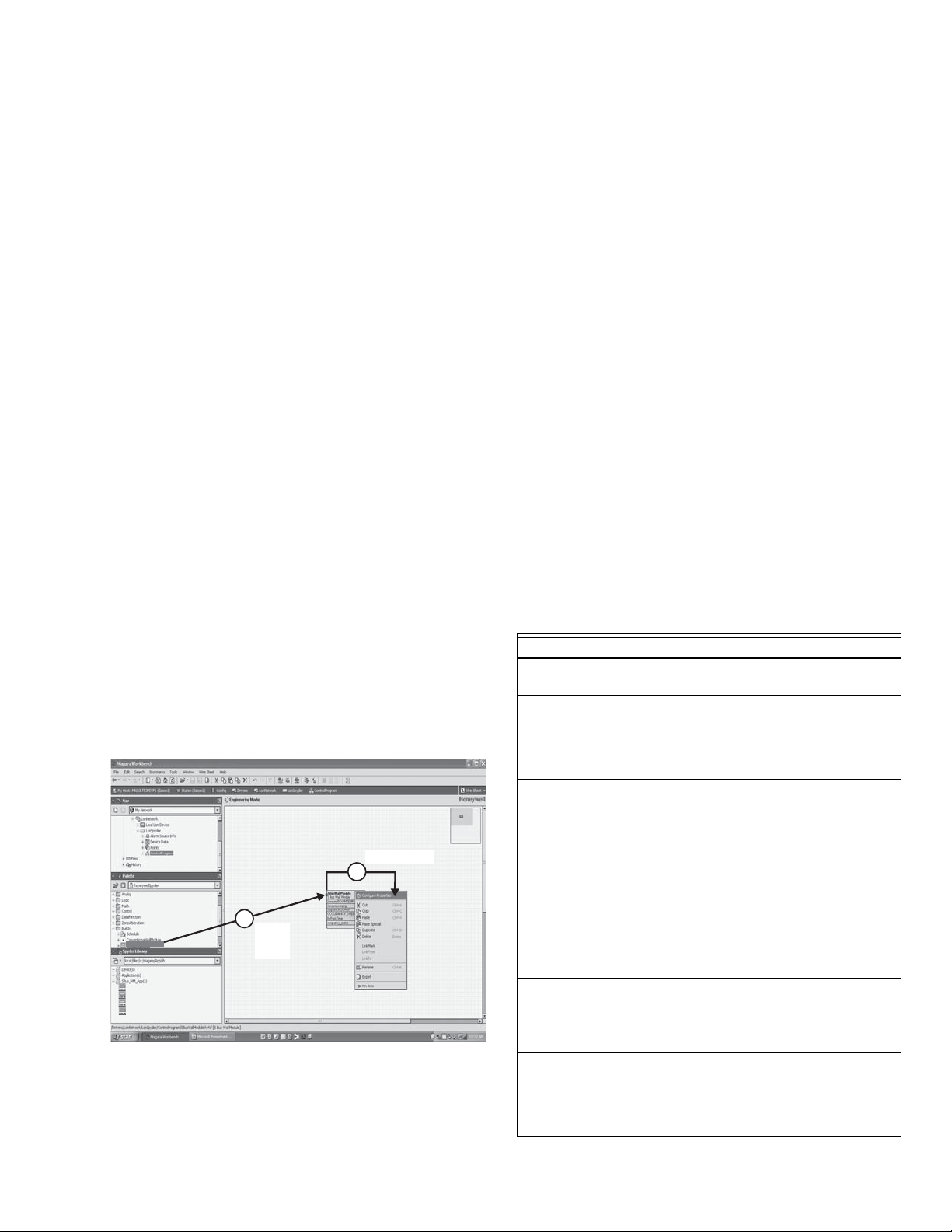
Selecting the Wall Module
You will use the Sylk S-Bus wall module function block from
the Palette’s Built-In folder (see Fig. 3). This configuration has
nothing programmed except the room temperature parameter
and occupancy status.
1. Add the Sylk S-Bus Wall Module function block to the
wire sheet via a left click, drag, and drop. See callout 1
in Fig. 3.
2. Right click on the S-Bus Wall Module function block to
open the Configuration Properties menu. See callout 2
in Fig. 3.
3. Left click on the title, Configuration Properties. This
action starts the Configuration Wizard. The Configuration Wizard steps (see Fig. 5 on page 4) are used to
configure the wall module.
Fig. 3. Niagara Tool Interface - S-Bus wall module selection.
TR71/TR75 Labels
The TR71/TR75 allows the use of the following special
characters in label fields such as Categories and Parameter
Names: underscore ( _ ) to insert a space, hyphen ( - ), and
forward slash ( / ). The TR70 allows use of the underscore
( _ ) character to insert a space.
Navigation and Memory Usage
The Honeywell Spyder Tool uses an intuitive, window-based
interface. A Help button on each screen provides assistance
with any entry or process.
IMPORTANT
NOTE: At any time, clicking the Preview button (lower left of
Navigation
Table 3 describes the navigation buttons at the bottom of the
wall module window. See the bottom of Fig. 7 on page 5 for
the location of these buttons. Buttons are greyed when
unavailable.
Help When clicked, this button provides context sensitive
Preview When clicked, this button displays the updated wall
Save to
Library
Back Takes you backward one step in the wizard
Next Takes you forward one step in the wizard interface.
Finish Clicking this button commits all changes to the
Cancel Prompts you with a confirmation message.
Use the Help button to display context specific help
for the current window or pane display. See the lower
left corner of Fig. 6 on page 5 for the location of the
Help button.
main window, see Fig. 6 on page 5) displays the
updated wall module LCD as a pop-up. Preview simulates the actual wall module interface and allows
you to verify the operation of the current configuration of the wall module. See “Preview” on page 16.
Table 3. Navigation Buttons.
Item Function/Use
help for the currently selected item or parameter.
module LCD in a pop-up window pane. Preview is
fully interactive and simulates the actual wall
module interface as currently configured (see
“Preview” on page 16 for details).
For new custom configurations and standard
configurations.
Clicking the button opens the Save to Library
screen (shown in Fig. 25 on page 17). This action
allows you to save the entire current wall module
configuration.
The Save to Library button is disabled until you
change the configuration (application). After a
change is made, you can save the new
configuration into the library under a new name.
interface.
database, closes the Configuration Wizard, and
returns you to the wire sheet.
If you reply Yes, then all selections/entries made
since the Save to Library button or Finish button
was last pressed are ignored, and the wizard
interface quits.
3 63-2719—03
ZIO®/ZIO PLUS LCD WALL MODULES
SAVE BUTTON
A SAVE button is available on screens that allow entries or
selections. It is enabled whenever any change is made on the
screen, and allows you to save your selections/entries at any
time. See the ROOMSP Details area of the Categories and
Parameters window in Fig. 12 on page 7 for an example of the
SAVE button.
Save is enabled whenever a change is made to the current
page. When you press the SAVE button, the preview screen
displays and your changes are reflected in the preview.
If you try to leave the current screen without saving (click
another icon or press the Back or Next button) and have made
changes, a warning message appears.
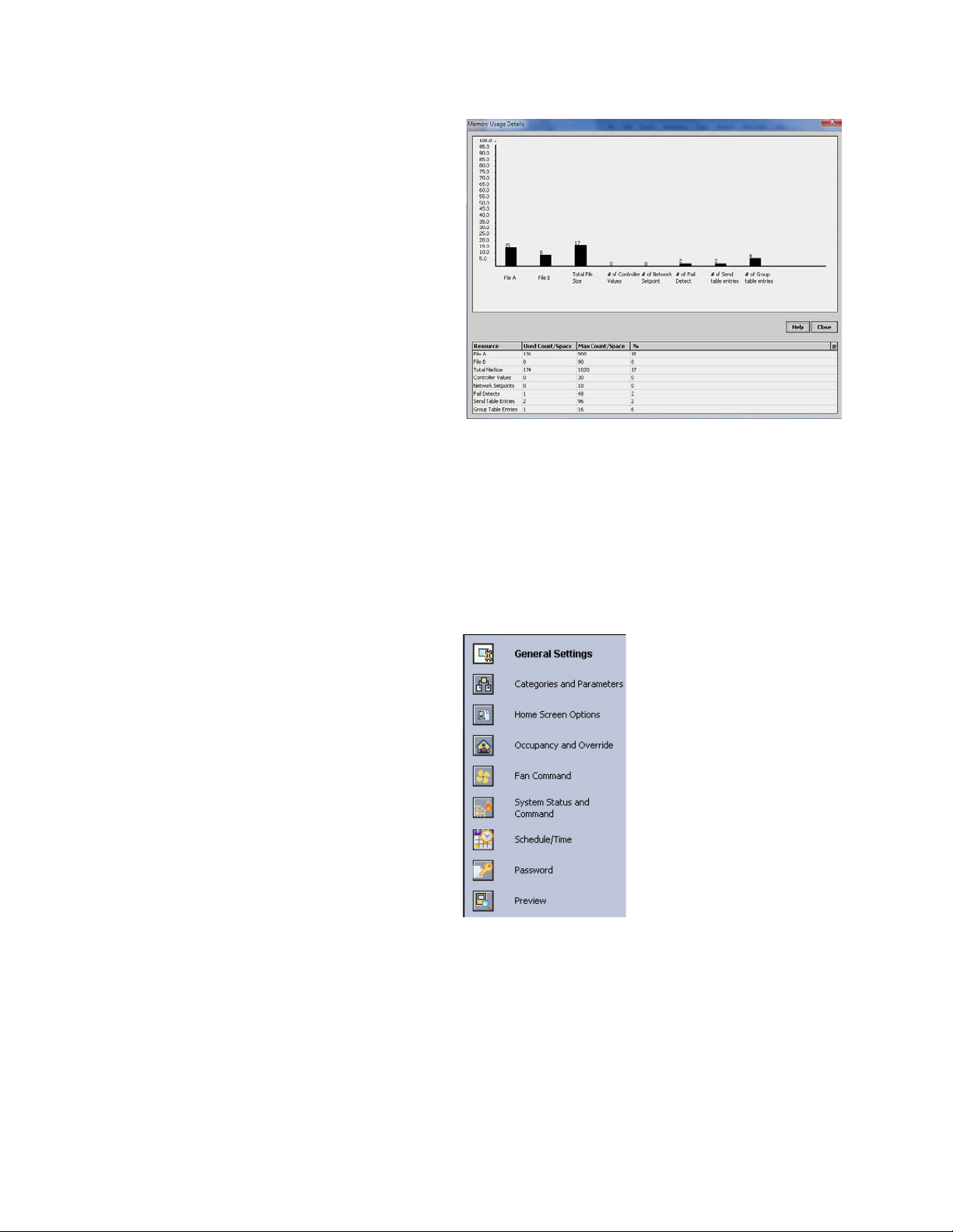
Memory Usage
The wall module has a fixed amount of memory available for
configuration data. The TR70 has 1,020 bytes of memory, the
TR71 has 2,000 bytes of memory, and the TR75 has 4,950
bytes of memory. To view the current memory use information
click on the Memory Usage Details button. A new window
opens and displays a bar graph indicating the percentage of
current memory used in each memory category.
Each of the memory categories should be below 100%. See
Fig. 4 on page 4.
NOTE: For a single Zio memory usage must be equal to or
less than 100% in order to download the configuration to the programmable controller. If using multiple
Zios, you should also check the Spyder Resource
usage. Total Zio memory use is limited to 5K bytes
on Spyder.
Fig. 4. Memory Usage Details screen.
Wall Module Configuration
To begin configuring the wall module:
1. Right click on the configuration’s function block to open
the Configuration Properties menu.
2. Left click on Configure Properties. The Configuration
Wizard opens. The Configuration Wizard steps (see Fig.
5) are used to configure the wall module.
View the online help in the WEBs-AX Workbench to see
troubleshooting tips for reducing memory usage in the TR70
Series if memory use is above 100%.
The following warning message displays when the memory
usage is greater than 100%:
“Warning: Memory Limit Exceeded. The current wall
module configuration requires more memory than the wall
module model can support. You will need to change the
configuration so that the memory usage is 100% or less
before pressing the FINISH button.”
See “General Settings”.
See page 5.
See page 9.
See page 10.
See page 12.
See page 13.
See page 14.
See page 15.
See page 16.
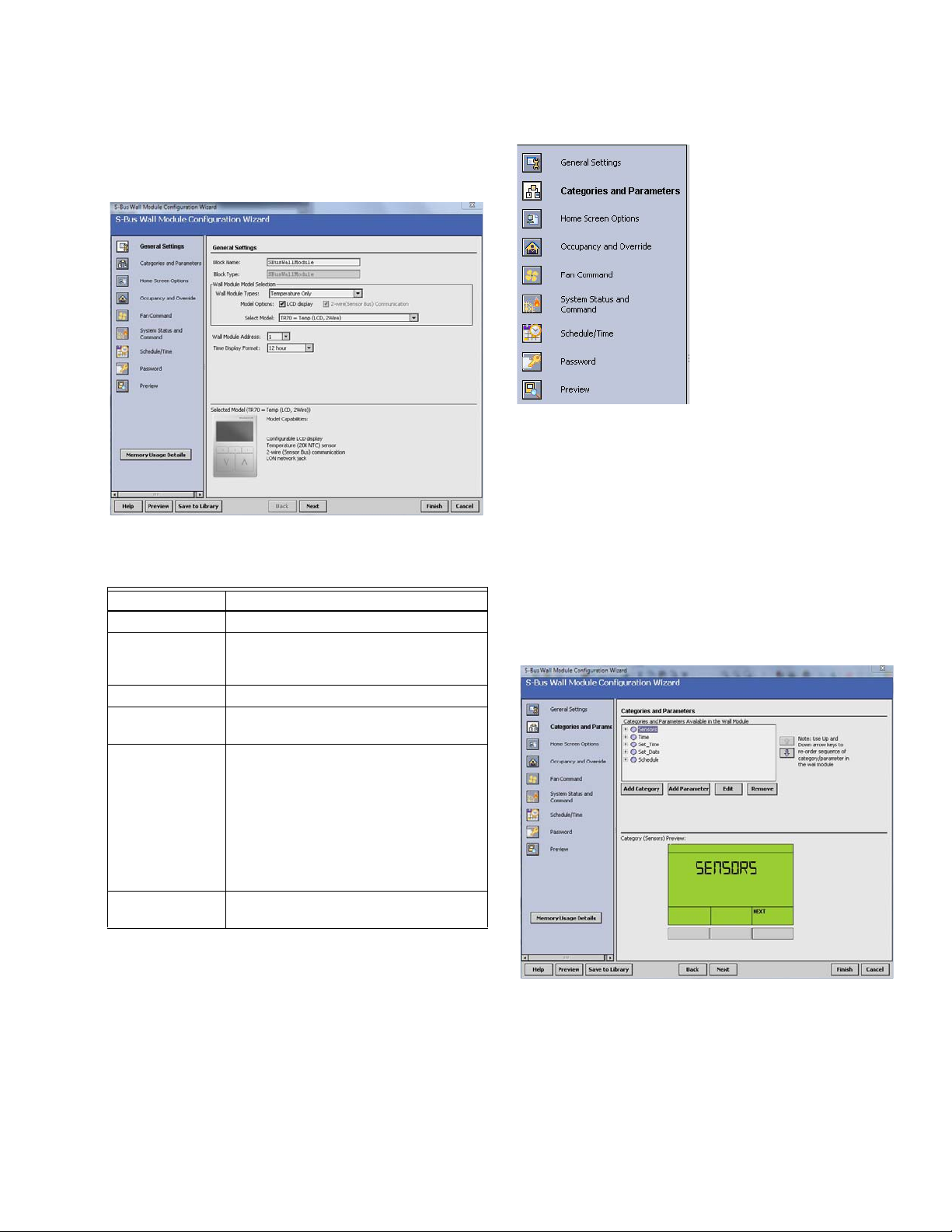
Fig. 5. Wall Module - Configuration Wizard window showing
Menu selections only.
63-2719—03 4
ZIO®/ZIO PLUS LCD WALL MODULES
General Settings
Using Fig. 6 and Table 4 as a guide, configure the General
Settings. An image of the selected model and its capabilities
updates in the display at the bottom of the window.
Fig. 6. General Settings screen.
Table 4. General Settings.
Item Function/Use
Block Name The wizard displays S-Bus Wall Module.
Wall Module
Ty pe
Model Options Click LCD Display.
Select Model Select the appropriate model, TR70,
Wall Module
Address
Time Display
Format
If you are creating a customized configuration or modifying a
pre-programmed configuration, continue with “Categories and
Parameters” on page 5.
If you are using a pre-programmed configuration as is,
continue with “Preview” on page 17.
Select the appropriate type (Temperature
Only, or a combination of Temperature,
and/or Humidity) from the drop down list.
TR71, or TR75, from the drop down list.
Select a unique address for each TR70
Series devices connected to the Spyder.
TR70 can be set from 1-5 and TR71/
TR75s can be set from 1-10. The
address selected must match the
address setting at the wall module (using
the rotary switches). If setting the TR71/
TR75 rotary switch to 0, set the address
to 10 in the configuration tool.
Select 12 or 24 hour format.
Categories and Parameters
I Categories and
Parameters selection from
Wizard Menu
The categories and parameters menu item allows you to
create, edit, and delete categories and parameters.
ADDING A CATEGORY
Fig. 7 shows the categories listed in tree format in the main
window where you can add, edit, or remove them. In the
bottom pane, Category Preview (at the bottom of Fig. 7)
shows the current selected item.
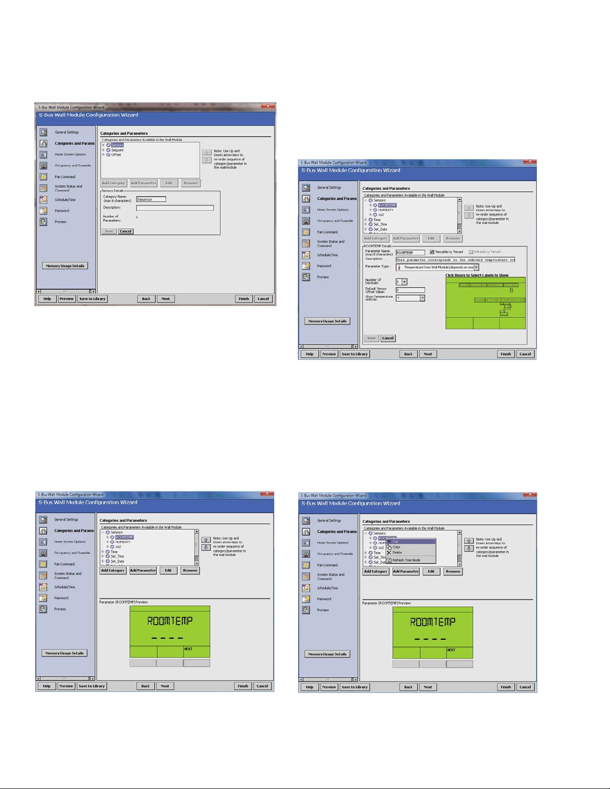
Clicking the Add Category button displays a details pane
below the category and parameter tree as shown in Fig. 8.
NOTE: You can use the Remove button to delete unused
categories and parameters to free up memory
space.
Fig. 7. Category Preview.
CATEGORY DETAILS
When you select a category from the Categories tree list and
click the Edit button, a details pane displays for that category
(see Fig. 8 on page 6).
Here you can enter a category name and description. The
number of parameters in this category are shown. The
description text you enter is loaded to the controller but cannot
be seen in the preview.
5 63-2719—03
ZIO®/ZIO PLUS LCD WALL MODULES
Fig. 8. Adding a Category.
Here you can select Viewable by Tenant and Editable by
Tenant.
As an example, Fig. 10 shows the Details for the ROOMTEMP
parameter. Here you would enter the description, select the
parameter type from its drop-down list, enter the decimal
accuracy, default sensor offset value, temperature units, and
select the desired Home screen labels for the wall module.
ADDING A PARAMETER
Fig. 9 shows the categories and parameters listed in tree
format in the main window. The parameters are listed under
each category. Click on the box next to the category item to
expand that item in the tree. You can add, edit, or remove
parameters under each category. In the bottom pane,
Category Preview (at the bottom of Fig. 9) shows the current
selected item.
Clicking the Add Parameter button displays a details pane
below the category and parameter tree as shown in Fig. 10.
NOTE: You can use the Remove button to delete unused
categories and parameters to free up memory
space.
Fig. 10. Adding a Parameter.
CUT/COPY/DELETE CATEGORIES AND PARAMETERS
A right-click accessible context menu allows you to cut, copy,
paste, and delete parameters across categories. See Fig. 11.
You can also drag/drop parameters in the tree and the result is
a copy/paste per standard Niagara behavior.
You can also click (highlight) any item in the tree and then click
the Remove button to delete any selected parameter or its
category.
Fig. 9. Parameter Preview.
PARAMETER DETAILS
When you select a parameter from the tree list and click the
Edit button, a details pane displays for that parameter.
63-2719—03 6
Fig. 11. Cut/Copy/Delete Categories and Parameters.
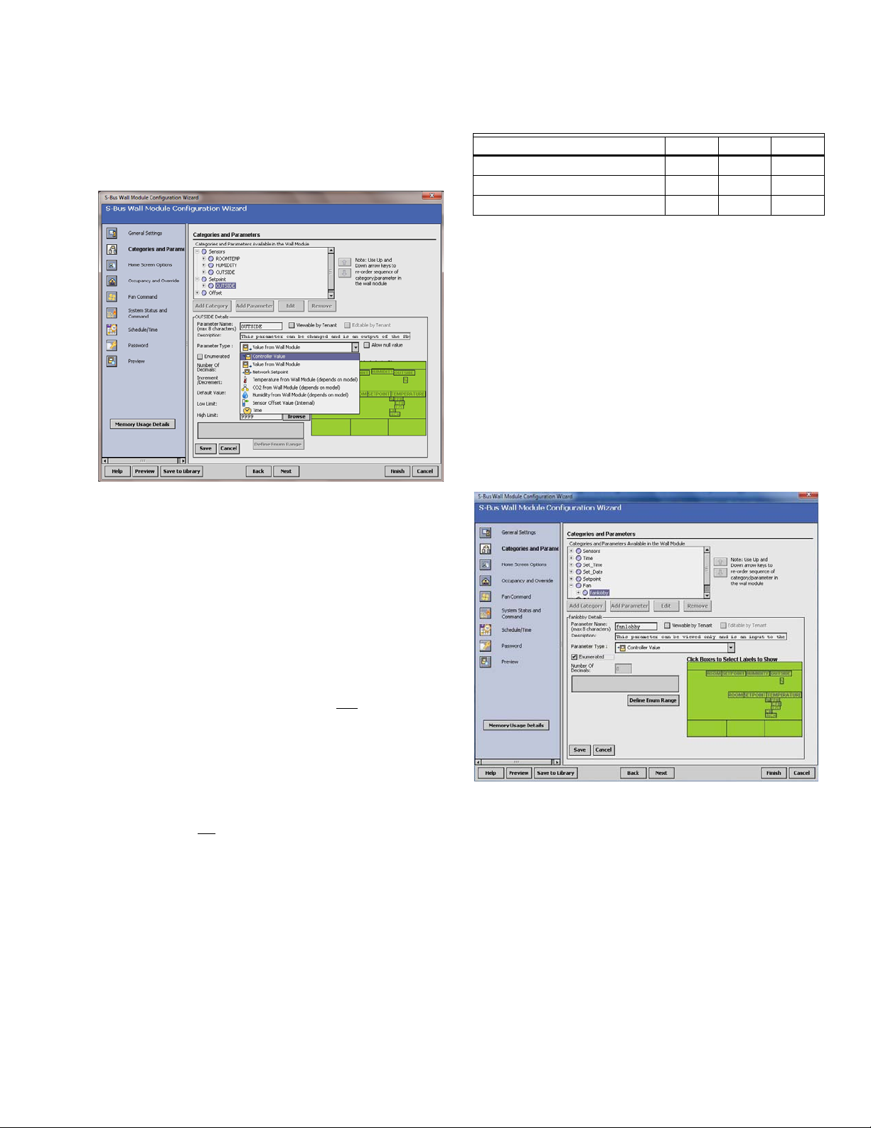
PARAMETER TYPES AND LIMITS
See Fig. 12 for an illustration of the Parameter Type drop
down list. There is a limit to the number of parameters that can
be configured. In addition to the parameter limit, there is also a
memory limit (see “Memory Usage” on page 4).
ZIO®/ZIO PLUS LCD WALL MODULES
Table 5. TR70 Series Parameter Capacity Guidelines.*
Parameter Type TR70 TR71 TR75
Controller Value 30 95 250
Value From Wall Module 20 50 180
Network Setpoints 10 50 125
* The TR71/TR75 may vary from these capacity numbers
depending on label names, parameter limit reuse, and other
devices that Zio interacts with on the Sylk bus.
NOTE: Network Variables need to be linked to the appropri-
ate S-Bus wall module’s function block slots. See
“Link Slots on the Wire Sheet” on page 18 for details.
PARAMETER OPTIONS
The TR71 and TR75 support additional parameter control.
See Table 1 on page 2 for details.
ENUMERATED VALUES
Meaningful enumerated values can be displayed using the
Enumerated option.
From the Add/Edit parameter window check the Enumerated
box and click on the Define Enum Range as shown in Fig. 13.
Fig. 12. Parameter Type selection.
The individual parameters are defined as:
— Controller Value
• These are read-only inputs to the wall module from
the controller and include system status and
occupancy status, if configured. Controller Value
parameters take up less memory than other
parameters.
— Value From Wall Module
• These are outputs from the wall module such as
room setpoint.
— Network Setpoints
• A network setpoint is a network variable from the
controller that you want to view and
wall module.
— Sensors
• 2 sensors (Temperature and Humidity)
• 2 Sensor Offset Values (temperature and humidity)
See Table 5 for the individual parameter maximums.
change at the
IMPORTANT
You can not
maximize all of these parameters
together. The size of the data files limits the total
number. See the memory usage tool by clicking on
the Memory Usage Details button in the left pane of
the Configuration Wizard.
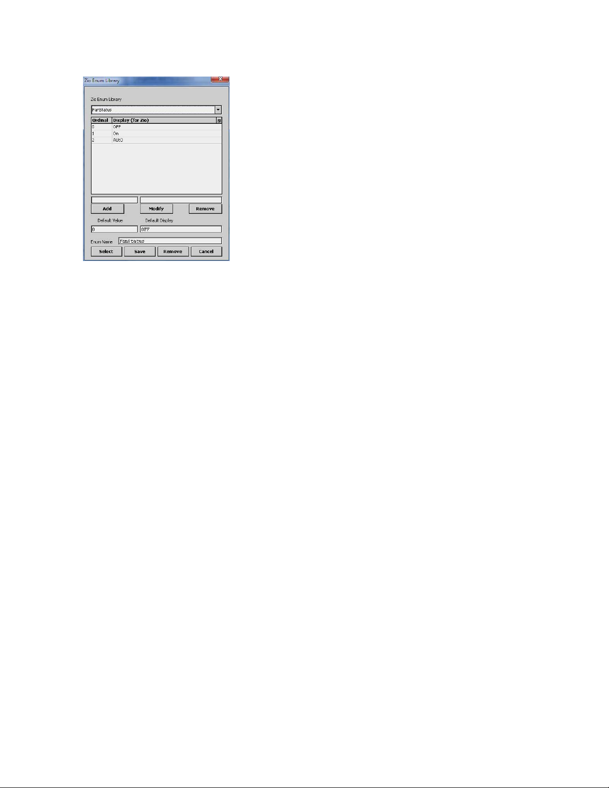
Fig. 13. Click on the Enumerated Checkbox, then the Define
Enum Range button.
Once in the Zio Enum Library dialog box (Fig. 14), click on the
dropdown to see pre-defined facets or define your own. For
more detailed information see the online help in the
Configuration Wizard.
7 63-2719—03
ZIO®/ZIO PLUS LCD WALL MODULES
Fig. 14. Select from the existing library or define enumerated
values.
HIGH/LOW LIMIT PARAMETER LINKING
This option allows for changes to a setpoint's high or low limit
directly at a Zio by linking the high and low limit to a related
setpoint. For example, for an occupied heat parameter, you
could assign the related unoccupied heat setpoint parameter
as the low limit and the occupied cooling setpoint parameter
as the high limit. To assign a setpoint to another setpoint's
high or low limit, click on the Browse button next to the Low
Limit or High Limit field. From the Select Parameter dialog box
you can select the appropriate setpoint.
This feature is an alternative to assigning a numeric value in
the High/Low Limit fields, which require any change be made
in the configuration tool and then loaded to Spyder.
Continue with “Home Screen Options” on page 9.
63-2719—03 8
 Loading...