

Page 1
Zio™ LCD Wall Modules
TR70 AND TR70-H with Sylk™ bus
PREFACE
This Operating Guide is intended to provide configuration
information (using the Niagara Workbench tool) and a general
overview of the TR70 operator interface. Configuration begins
with “Initial Power-up” on page 2, and the general overview
begins with “Operating the Zio Wall Module” on page 22.
It is intended to guide you through the features and operation
of the TR70 as you interface with the programmable controller
and establish pre-programmed or custom configurations.
OPERATING GUIDE
LCD PANEL
APPLICATION
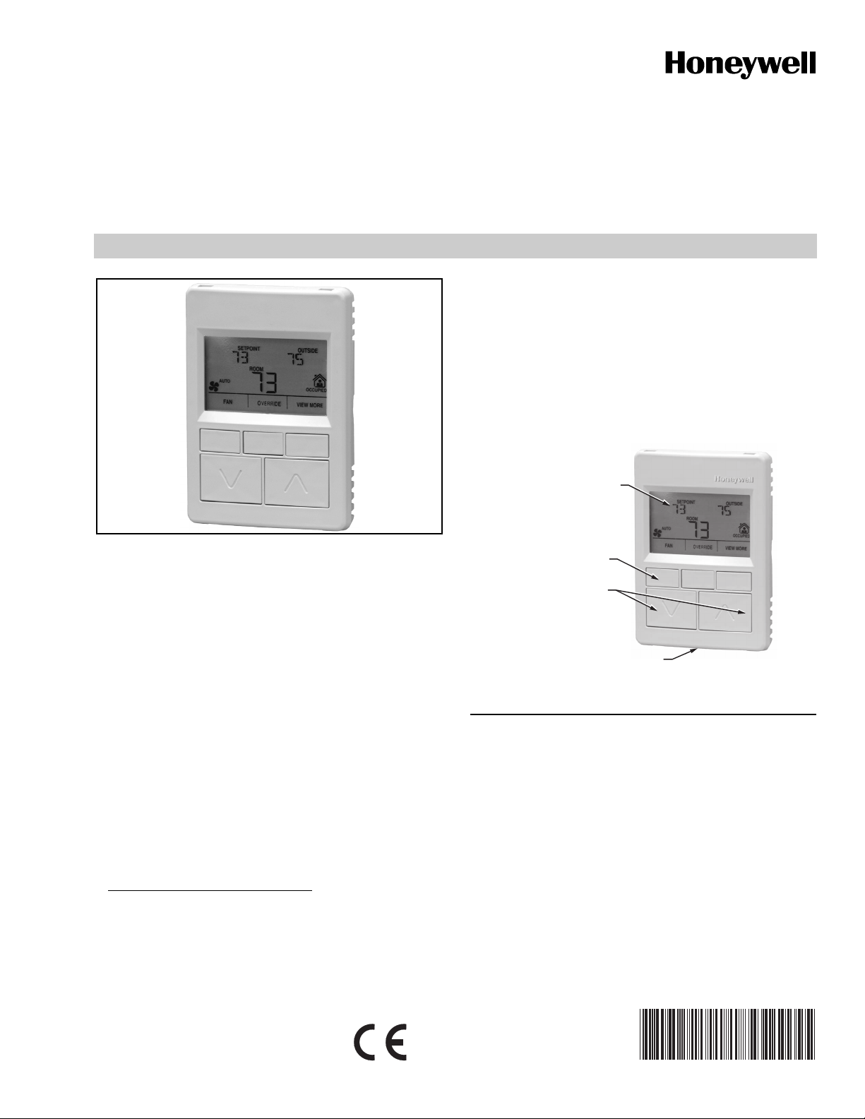
The TR70 and TR70-Ha LCD Wall Modules provide an
operator interface for monitoring and adjusting parameters in
the wall module itself and in the programmable controllerb to
which it is wired. The wall module may be customized and
supports both a contractor and a tenant user interface.
NOTE: This document illustrates the wall module
The wall module has a snap in mounting to a subbase that
may be mounted on a wall, on a standard utility conduit box,
or on a 60 mm wall outlet box. Wiring connections to the wall
module are made through a cutout in the back of the wall
module.
All models have a space temperature sensor, network bus
jack, and an LCD panel with three softkeys and two Up/Down
adjustment keys.
a
The TR70-H model includes an onboard humidity sensor.
b
Refer to the Honeywell Spyder User’s Guide (form 63-2662)
or the ComfortPoint™ Programmable Controller User’s
Guide (form 63-2663) depending on the programmable controller used.
configuration process using information from the
Honeywell Spyder™ User’s Guide (form 63-2662).
SOFTKEYS (3)
UP/DOWN
ARROW KEYS
NETWORK BUS PORT (ON BOTTOM OF CASE)
Fig. 1. LCD Wall Module features.
M27344
Contents
Initial Power-up ................................................................. 2
Setup and Configuration ................................................... 2
Initial Setup and Configuration .................................. 2
Selecting the Wall Module ......................................... 2
Pre-Programmed Configurations .............................. 3
Wall Module Configuration ........................................ 6
General Settings ................................................... 6
Categories and Parameters .................................. 7
Home Screen Options ........................................... 10
Occupancy and Override ...................................... 11
Fan Command ...................................................... 13
System Status and Command ............................... 14
Preview ................................................................. 15
Completing the Setup and Configuration .......................... 16
Operating the Zio Wall Module ......................................... 22
Contractor Mode Operation ...................................... 22
Tenant Mode Operation ............................................ 24
63-2667-01
Page 2
ZIO™ LCD WALL MODULES
Compatibility
The Zio LCD Wall Modules operate with the Sylk Enhanced
Spyder Controller or the Sylk Enhanced ComfortPoint
Controller.
INITIAL POWER-UP
IMPORTANT
1. Make sure the TR70 wall module is properly
mounted and properly wired and connected to the
programmable controller.
2. Refer to the Zio™ LCD Wall Modules TR70 and
TR70-H with Sylk™ bus – Installation Instructions,
form 62-0271, for specific installation requirements.
Upon initial power-up before configuring the wall module, the
LCD screen displays the phrase “PLEASE LOAd” in the Label/
Value area of Fig. 2. This phrase alternates with any onboard
sensor display such as temperature.
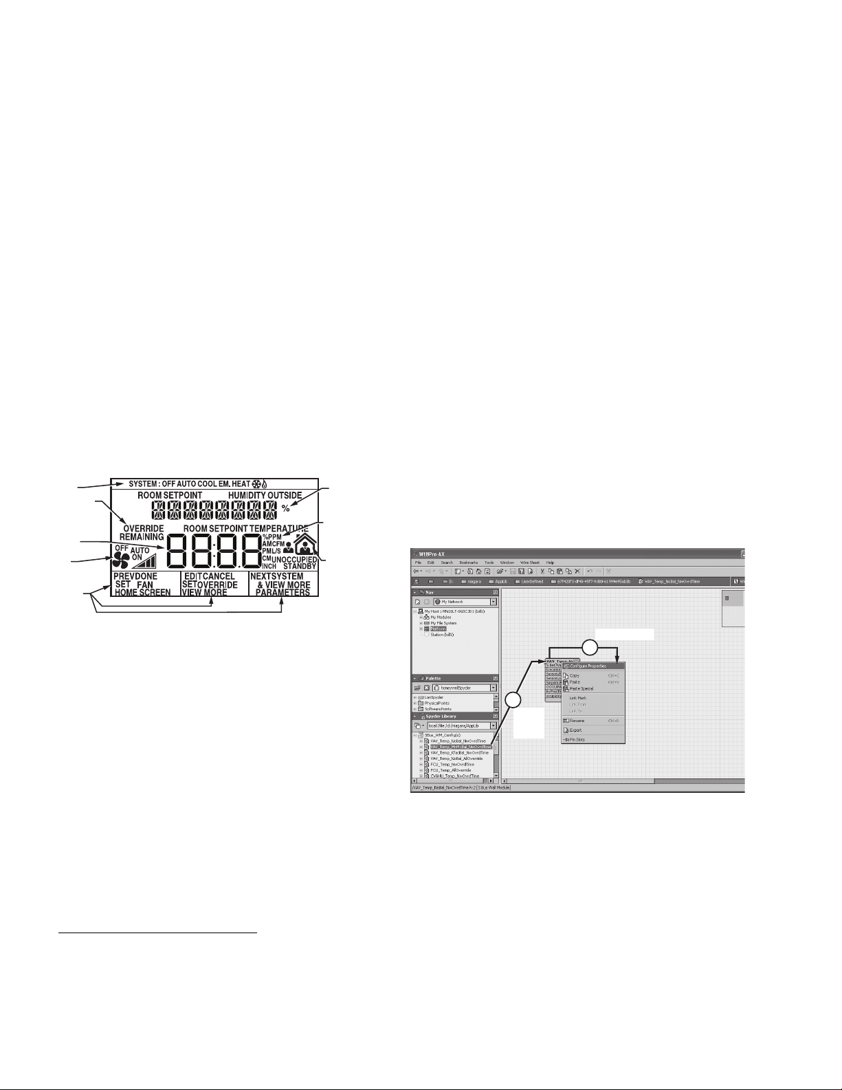
Fig. 2 illustrates all the possible LCD Wall Module display
elements. Only those elements pertinent to the current
configuration and status actually display.
SYSTEM
STATUS
AREA
OVERRIDE
INFORMATION
CURRENT
DISPLAYED
VALUE
FAN
INFORMATION
SOFTKEY
LABELS
LABEL/
VALUE
(8 CHAR.)
ENGINEERING
UNITS
OCCUPANCY
STATUS
M27353
NOTE: Multi-drop installations are not available at this time.
Only one wall module may be wired to the
programmable controller.
Selecting the Wall Module
There are two ways to configure the wall module:
• Select one of the 16 pre-programmed configurations within
the Spyder Library (the most commonly used method).
- or -
• Select the un-programmed S-Bus wall module
configuration.
NOTE: The 16 pre-programmed configurations satisfy most
application requirements. You can select a preprogrammed configuration and then Preview it to see
if it works for your application.
Selecting a Pre-Programmed Configuration
There are 16 pre-programmed configurations located in the
Spyder Library. See Fig. 3 for a sample screen shot of the tool
interface showing the Spyder Library and see “PreProgrammed Configurations” on page 3 for descriptions.
1. Add the desired configuration to the wire sheet via a left
click, drag, and drop. See callout 1 in Fig. 3.
2. Right click on the configuration’s function block to open
the Configuration Properties menu. See callout 2 in
Fig. 3.
3. Left click on the title, Configuration Properties. This
action starts the Configuration Wizard. The
Configuration Wizard steps (see Fig. 6 on page 6) are
used to configure the wall module.
Fig. 2. TR70 Wall Module - LCD screen.
SETUP AND CONFIGURATION
Initial Setup and Configuration
Once the wall module is wired to the controller, you configure
the wall module using the PC-based, Niagara Workbench
Tool. Refer to the applicable programmable controller User’s
a
Guide.
either the Spyder or the ComfortPoint programmable
controller.
Confirm Bus Address Setting
Check to ensure that the Wall Module’s bus address dial
(located on the back of the module) is set to one (1) to match
the default setting of the configuration tool.
a
This tool is used to configure the wall module for
Refer to the Honeywell Spyder User’s Guide (form 63-2662)
or the ComfortPoint Programmable Controller User’s Guide
(form 63-2663) depending on the programmable controller
used.
RIGHT CLICK
2
1
DRAG
AND
DROP
Fig. 3. Niagara Tool Interface - pre-programmed
configuration selection.
M27819
63-2667—01 2
Page 3
ZIO™ LCD WALL MODULES
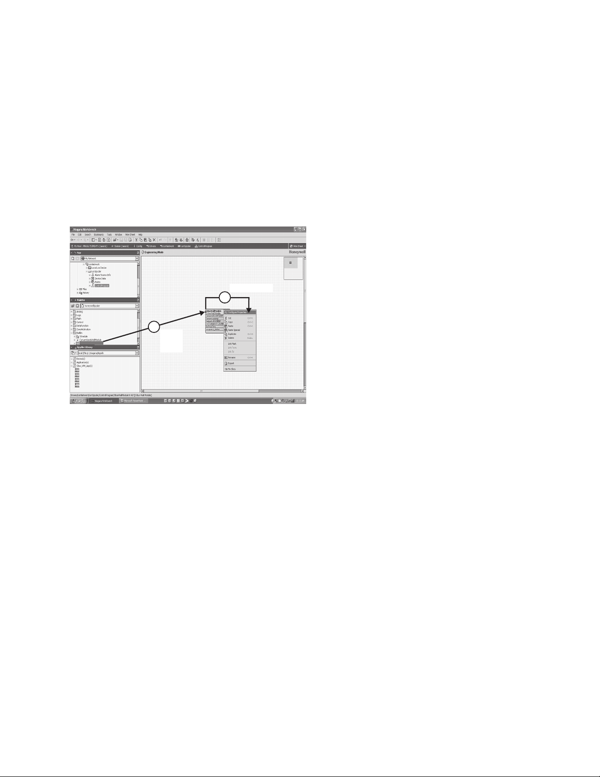
Selecting the Un-programmed S-Bus Wall Module
You may use the Sylk S-Bus wall module function block from
the Palette’s Built-In folder (see Fig. 4). This configuration has
nothing programmed except the room temperature parameter.
1. Add the Sylk S-Bus Wall Module function block to the
wire sheet via a left click, drag, and drop. See callout 1
in Fig. 4.
2. Right click on the S-Bus Wall Module function block to
open the Configuration Properties menu. See callout 2
in Fig. 4.
3. Left click on the title, Configuration Properties. This
action starts the Configuration Wizard. The
Configuration Wizard steps (see Fig. 6 on page 6) are
used to configure the wall module.
RIGHT CLICK
2
1
DRAG
SBusWallModule
VAV_Temp_NoBal_NwOvrdTime
VAV_Temp_MnMxBal_NwOvrdTime
VAV_Temp_KfacBal_NwOvrdTime
VAV_Temp_NoBal_AllOverride
Fig. 4. Niagara Tool Interface - un-programmed S-Bus wall
AND
DROP
M27820
module selection.
Configurations - Typical for TR70 Wall Modules
VAV_Temp_NoBal_NwOvrdTime
Typical set-up for a VAV system. No balancing loaded, which
frees up additional memory if greater controller parameter
access is desired. Uses the network determined occupied
override duration.
VAV_Temp_MnMxBal_NwOvrdTime
Typical set-up for a VAV system pre-configured with a Min/
Max Airflow balancing method (balancing can be done
through the wall module keypad), and uses the network
determined occupied override duration.
VAV_Temp_KfacBal_NwOvrdTime
Typical set-up for a VAV system pre-configured with a KFactor method of balancing (balancing can be done though
the wall module keypad), and uses the network determined
occupied override duration.
VAV_Temp_NoBal_AllOverride
Typical set-up for a VAV system. No balancing loaded, which
frees up additional memory if greater controller parameter
access is desired. Loaded with a user adjustable occupied
override time from 30 minutes to 3 hours, as well as an
adjustable vacation (multiple day) override (unoccupied), and
a continuous unoccupied time.
FCU_Temp_NwOvrdTime
Typical set-up for a fan coil system pre-configured to use the
network determined occupied override duration.
FCU_Temp_AllOverride
Typical set-up for a fan coil system pre-configured to use the
network determined occupied override duration. Loaded with
a user adjustable occupied override time from 30 minutes to 3
hours, as well as an adjustable vacation (multiple day)
override (unoccupied), and a continuous unoccupied time.
Pre-Programmed Configurations
The 16 pre-programmed configurations are starting points for
customization. Just drag the configuration out of the Spyder
Library (See “Selecting a Pre-Programmed Configuration” on
page 2.), then start customizing it and making the required
links in the wire sheet. You can select from the menu items
(e.g. Home Screen Options; see Fig. 6 on page 6), make your
changes, and save it as a custom configuration to complete
the configuration process.
NOTE: If one of the pre-programmed configurations works
for your application, then you can simply complete
this section, preview it, and finish the configuration
process by going to “Completing the Setup and
Configuration” on page 16.
Each configuration includes:
• A default Home screen showing room temperature, room
setpoint, and either outside air or indoor humidity.
• Seven additional Home screens choices are also preloaded.
Use the full-featured Preview option in the wall module tool to
demo the configuration. See “Preview” on page 15.
CVAHU_Temp_NwOvrdTime
Typical set-up for a CVAHU system pre-configured to show
system status and system override (heat, cool, auto, etc., like
a thermostat), and uses the network determined occupied
override duration.
CVAHU_Temp_AllOverride
Typical set-up for a CVAHU system pre-configured to show
system status and system override (heat, cool, auto, etc., like
a thermostat). This status can be removed. Loaded with a
user adjustable occupied override time from 30 minutes to 3
hours, as well as an adjustable vacation (multiple day)
override (unoccupied), and a continuous unoccupied time).
3 63-2667—01
Page 4
ZIO™ LCD WALL MODULES
Configurations including Humidity
These configurations are typical for TR70-H Wall Modules.
The following configurations are equivalent to the TR-70
configurations, but these include the Humidity parameter.
— VAV_TempHum_MnMxBal_NwOvrdTime
— VAV_TempHum_KfacBal_NwOvrdTime
— VAV_TempHum_NoBal_NwOvrdTime
— VAV_TempHum_NoBal_AllOverride
— FCU_TempHum_NwOvrdTime
— FCU_TempHum_AllOverride
— CVAHU_TempHum_NwOvrdTime
— CVAHU_TempHum_AllOverride
NOTE: At any time, any of the 16 configurations can be
modified and saved to the library with a new
configuration name. See Fig. 21 on page 16 for an
illustration of the Save to Library pop-up window.
Navigation and Memory Usage
The Honeywell Spyder Tool uses an intuitive, window-based
interface. A Help button on each screen provides assistance
with any entry or process.
IMPORTANT
Use the Help button to display context specific help
for the current window or pane display. See the lower
left corner of Fig. 7 on page 6 for the location of the
Help button.
NOTE: At any time, clicking the Preview button (lower left of
main window, see Fig. 7 on page 6) displays the
updated wall module LCD as a pop-up. Preview
simulates the actual wall module interface and allows
you to verify the operation of the current
configuration of the wall module. See “Preview” on
page 15.
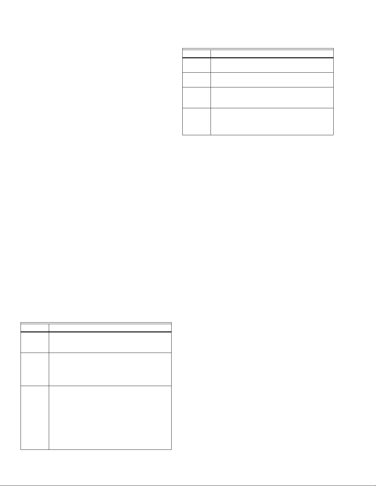
Table 1. Navigation Buttons. (Continued)
Item Function/Use
Back Takes you backward one step in the wizard
interface.
Next Takes you forward one step in the wizard
interface.
Finish Clicking this button commits all changes to the
database, closes the Configuration Wizard, and
returns you to the wire sheet.
Cancel Prompts you with a confirmation message.
If you reply Yes, then all selections/entries made
since the Save to Library button was last pressed
are ignored, and the wizard interface quits.
SAVE BUTTON
A SAVE button is available on screens that allow entries or
selections. It is enabled whenever any change is made on the
screen, and allows you to save your selections/entries at any
time. See the ROOMSP Details area of the Categories and
Parameters window in Fig. 13 on page 9 for an example of the
SAVE button.
Save is enabled whenever a change is made to the current
page. When you press the SAVE button, the preview screen
displays and your changes are reflected in the preview.
If you try to leave the current screen without saving (click
another icon or press the Back or Next button) and have made
changes, the LCD displays a warning message.
Memory Usage
The wall module has a fixed amount of memory available for
configuration data. A bar graph indicating current memory
usage is provided in the lower left of the wall module window.
See Fig. 8 on page 7.
Navigation
Table 1 describes the navigation buttons at the bottom of the
wall module window. See the bottom of Fig. 8 on page 7 for
the location of these buttons. Buttons are greyed when
unavailable.
Table 1. Navigation Buttons.
Item Function/Use
Help When clicked, this button provides context
sensitive help for the currently selected item or
parameter.
Preview When clicked, this button displays the updated
Save to
Library
wall module LCD in a pop-up window pane.
Preview is fully interactive and simulates the
actual wall module interface as currently
configured (see “Preview” on page 15 for details).
For new custom configurations and standard
configurations.
Clicking the button opens the Save to Library
screen (shown in Fig. 21 on page 16). This action
allows you to save the entire current wall module
configuration.
The Save to Library button is disabled until you
change the configuration (application). After a
change is made, you can save the new
configuration into the library under a new name.
NOTE: Memory usage must be less than 100% in order to
download the configuration to the programmable
controller.
If the memory bar graph is not visible, click the Show Wall
Module Memory Usage check box in the lower left of the
window. See the lower left corner of Fig. 8 on page 7 for an
illustration.
Right clicking on the bar graph displays details of how the
memory is currently being used.
The fill color of the bar graph changes according to the
following memory levels:
• Less than 90% = blue
• Greater than 90%, but less than 100% = orange
• Greater than 100% = red
The following warning message displays when the memory
usage is greater than 100%:
“Warning: Memory Limit Exceeded. The current wall
module configuration requires more memory than the wall
module model can support. You will need to change the
configuration so that the memory usage is 100% or less
before pressing the FINISH button.”
63-2667—01 4
Page 5
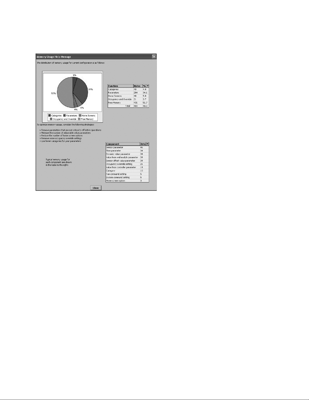
Clicking anywhere on the memory bar graph opens a pop up
to display the Help specific to memory management as
illustrated in Fig. 5.
ZIO™ LCD WALL MODULES
Fig. 5. Memory Usage Help screen.
5 63-2667—01
Page 6
ZIO™ LCD WALL MODULES
Wall Module Configuration
To begin configuring the wall module:
1. Right click on the configuration’s function block to open
the Configuration Properties menu. See callout 2 in
Fig. 3 on page 2.
2. Left click on the title, Configuration Properties. This
action starts the Configuration Wizard. The
Configuration Wizard steps (see Fig. 6) are used to
configure the wall module.
See “General Settings”.
See page 7.
See page 10.
See page 11.
See page 13.
See page 14.
See page 15.
Fig. 6. Wall Module - Configuration Wizard window
showing Menu selections only.
Table 2. General Settings.
Item Function/Use
Block Name The wizard displays S-Bus Wall Module.
Wall Module
Type
Select the appropriate type (Temperature
Only, or a combination of Temperature,
and/or Humidity) from the drop down list.
Model Options Click LCD Display.
Select Model Select the appropriate model, TR70 or
TR70-H, from the drop down list.
Wall Module
Address
Use the factory default, 1, for the wall
module connected to the programmable
controller.
Time Display
Select 12 or 24 hour format.
Format
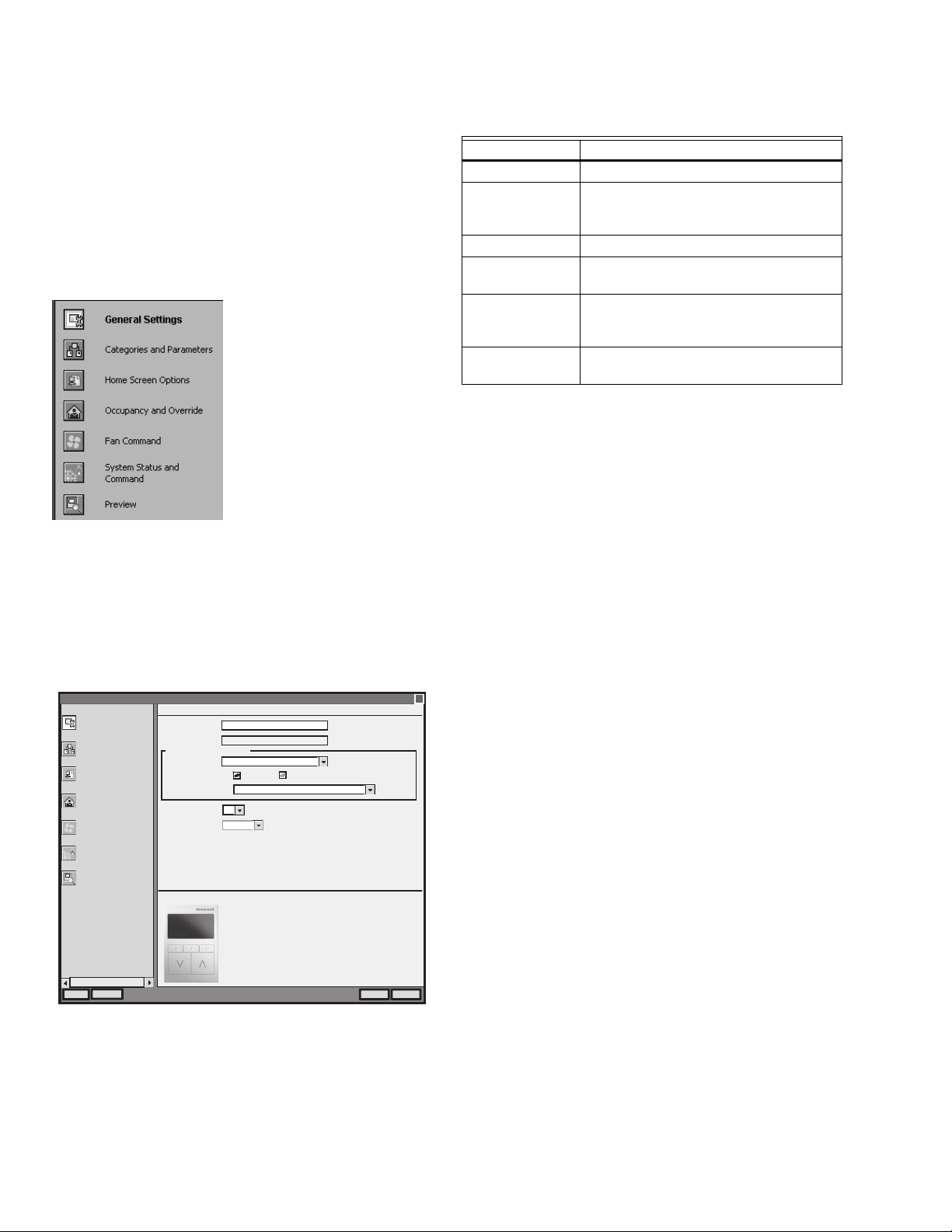
General Settings
Using Fig. 7 and Table 2 as a guide, configure the General
Settings. An image of the selected model and its capabilities
updates in the display at the bottom of the window.
Wall Module Configuration Wizard
General Settings
Categories and Parameters
Home Screen Options
Occupancy and Override
Fan Command
System Status and
Command
Preview
---
Preview
General Settings
Block Name:
Block Type:
Wall Module Model Selection
Wall Module Type:
Wall Module Address:
Time Display Format:
…
Selected Model (TR70 = Temp (LCD, 2Wire))
S-Bus Wall Module
WallModule
Temperature Only
Model Options:
Select Model:
1
12 hour
LCD Display
TR70 = Temp (LCD, 2Wire)
Model Capabilities:
-Temperature (20K NTC)
-2-wire (Sensor Bus) communication
-Configurable LCD display
-Navigation keypad
-Scroll keypad
-LON network jack
2-Wire (Sensor Bus) Communication2-Wire (Sensor Bus) Communication2-Wire (Sensor Bus) Communication
Fig. 7. General Settings screen (TR70 model shown).
x
CancelFinishHelp
M27821
X
If you are creating a customized configuration or modifying a
pre-programmed configuration, continue with “Categories and
Parameters” on page 7.
63-2667—01 6
If you are using a pre-programmed configuration as is,
continue with “Preview” on page 16.
Page 7
ZIO™ LCD WALL MODULES
Categories and Parameters
I Categories and
Parameters selection from
Wizard Menu
The categories and parameters menu item allows you to
create, edit, and delete categories and parameters.
Parameters, and editing of categories and parameters begin
on page 8.
ADDING A CATEGORY
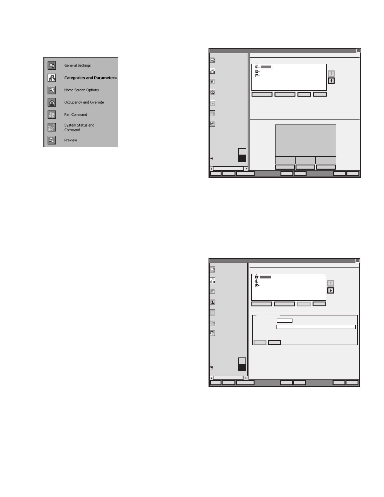
Fig. 8 shows the categories listed in tree format in the main
window where you can add, edit, or remove them. In the
bottom pane, Category Preview (at the bottom of Fig. 8)
shows the current selected item.
Clicking the Add Category button displays a details pane
below the category and parameter tree as shown in Fig. 9.
NOTE: You can use the Remove button to delete unused
categories and parameters to free up memory space.
Wall Module Configuration Wizard
General Settings
Categories and Parameter
Home Screen Options
Occupancy and Override
Fan Command
System Status and
Command
Preview
Categories and Parameters
Categories and Parameters Available in the Wall Module
SENSORS
SENSORS
SETPOINT
SETPOINT
OFFSET
OFFSET
Add Category Add Parameter
…
Category (SENSORS) Preview:
Note: Use ‘Up’ and
‘Down’ arrow keys to
re-order sequence of
category/parameter in
the wall module
Remove
Edit
SENSORS
Cancel
Show Wall Module
Show Wall Module
Memory Usage
Memory Usage
Preview
---
50%
50%
Save to Library
Fig. 8. Category Preview.
CATEGORY DETAILS
When you select a category from the Categories tree list and
click the Edit button, a details pane displays for that category
(see Fig. 9 on page 7).
Here you can enter a category name, description, and the
number of parameters for this category. The description text
you enter displays when you mouse over the Preview screen.
Wall Module Configuration Wizard
General Settings
Categories and Parameter
Home Screen Options
Occupancy and Override
Fan Command
System Status and
Command
Preview
Categories and Parameters
Categories and Parameters Available in the Wall Module
SENSORS
SENSORS
SETPOINTSETPOINT
OFFSET
Add Category Add Parameter
SENSORS Details
…
Category Name:
(max 8 characters)
Description:
Number of
Parameters:
SENSORS
3
CancelSave
--
NEXT SYSTEM
& VIEW MORE
PARAMETERS
CancelFinishNext >< BackHelp
M27363
X
Note: Use ‘Up’ and
‘Down’ arrow keys to
re-order sequence of
category/parameter in
the wall module
Remove
Edit
X
Show Wall Module
Show Wall Module
Memory Usage
Memory Usage
Preview
---
50%
50%
Save to Library
CancelFinishNext >< BackHelp
M27491
Fig. 9. Adding a Category.
7 63-2667—01
Page 8
ZIO™ LCD WALL MODULES
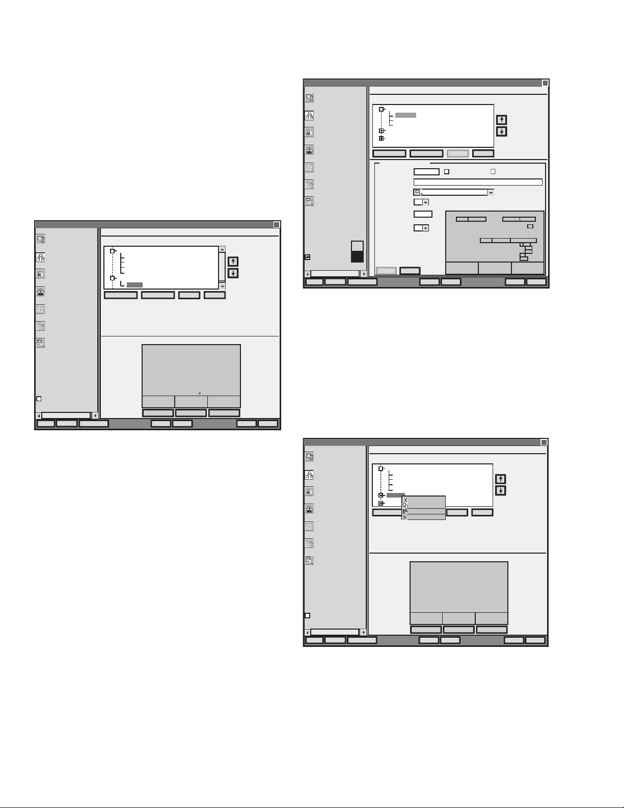
ADDING A PARAMETER
Fig. 10 shows the categories and parameters listed in tree
format in the main window. The parameters are listed under
each category. Click on the box next to the category item to
expand that item in the tree. You can add, edit, or remove
parameters under each category. In the bottom pane,
Category Preview (at the bottom of Fig. 10) shows the current
selected item.
Clicking the Add Category button displays a details pane
below the category and parameter tree as shown in Fig. 11.
NOTE: You can use the Remove button to delete unused
categories and parameters to free up memory space.
Wall Module Configuration Wizard
General Settings
Categories and Parameter
Home Screen Options
Occupancy and Override
Fan Command
System Status and
Command
Preview
Categories and Parameters
Categories and Parameters Available in the Wall Module
SENSORS
-
ROOMTEMP
HUMIDITY
CO2
OUTSIDE
SETPOINT
-
OUTSIDE
Add Category Add Parameter
…
Parameter (OUTSIDE) Preview:
Note: Use ‘Up’ and
‘Down’ arrow keys to
-
-
re-order sequence of
-
category/parameter in
the wall module
Remove
Edit
X
OUTSIDEH
Cancel
____
Show Wall Module
Memory Usage
---
Preview
Save to Library
Fig. 10. Parameter Preview.
PARAMETER DETAILS
When you select a parameter from the tree list and click the
Edit button, a details pane displays for that parameter.
Here you can select Viewable by Tenant and Editable by
Tenant.
As an example, Fig. 11 shows the Details for the ROOMTEMP
parameter. Here you would enter the description, select the
parameter type from its drop-down list, enter the decimal
accuracy, default sensor offset value, temperature units, and
select the desired Home screen labels for the wall module.
--
ROOM SETPOINT TE MPERATURE
NEXT SYSTEM
& VIEW MORE
PARAME TERS
CancelFinishNext >< BackHelp
M27492
Wall Module Configuration Wizard
General Settings
Categories and Parameter
Home Screen Options
Occupancy and Override
Fan Command
System Status and
Command
Preview
Show Wall Module
Show Wall Module
Memory Usage
Memory Usage
Preview
---
50%
50%
Save to Library
…
Categories and Parameters
Categories and Parameters Available in the Wall Module
SENSORS
-
ROOMTEMP
HUMIDITY
CO2
SETPOINT
OFFSET
Add Category Add Parameter
ROOMTEMP Details
Parameter Name:
(max 8 characters)
Description:
Parameter Type:
Number of
Decimals:
Default Sensor
Offset Value:
Show Temperature
Units As:
Save Cancel
ROOMTEMP
On board room temperature sensor
Temperature from Wall Module
0
0
°F
CancelSave
Edit
Viewable by Tenant
Click Boxes to Select Labels to Show
ROOM SETPOINT HUMIDITY OUTSIDE
Cancel
Note: Use ‘Up’ and
‘Down’ arrow keys to
re-order sequence of
category/parameter in
the wall module
Remove
Editable by Tenant
--
ROOM SETPOINT TEMPERATURE
%PPM
AM CFM
PM L/S
CM
INCH
X
%
CancelFinishNext >< BackHelp
M27493
Fig. 11. Adding a Parameter.
EDITING CATEGORIES AND PARAMETERS.
A right-click accessible context menu allows you to cut, copy,
paste, and delete parameters across categories. See Fig. 12.
You can also drag/drop parameters in the tree and the result is
a copy/paste per standard Niagara behavior.
You can also click (highlight) any item in the tree and then
click the Remove button to delete any selected parameter or
its category.
Wall Module Configuration Wizard
General Settings
Categories and Parameter
Home Screen Options
Occupancy and Override
Fan Command
System Status and
Command
Preview
Categories and Parameters
Categories and Parameters Available in the Wall Module
SENSORS
SENSORS
-
-
ROOMTEMP
ROOMTEMP
HUMIDITY
HUMIDITY
CO2
CO2
OUTSIDE
OUTSIDE
SETPOINT
SETPOINT
OFFSET
OFFSET
Add Category Add Parameter
Cut
Cut
Copy
Copy
Paste
Paste
Delete
Delete
Ctrl+X
Ctrl+X
Ctrl+C
Ctrl+C
Ctrl+V
Ctrl+V
Delete
Delete
…
Category (SETPOINT) Preview:
Note: Use ‘Up’ and
‘Down’ arrow keys to
re-order sequence of
category/parameter in
the wall module
Remove
Edit
X
SETPOINT
Cancel
--
63-2667—01 8
Show Wall Module
Memory Usage
---
Preview
Save to Library
Fig. 12. Editing Categories and Parameters.
NEXT SYSTEM
& VIEW MORE
PARAME TERS
CancelFinishNext >< BackHelp
M27494
Page 9
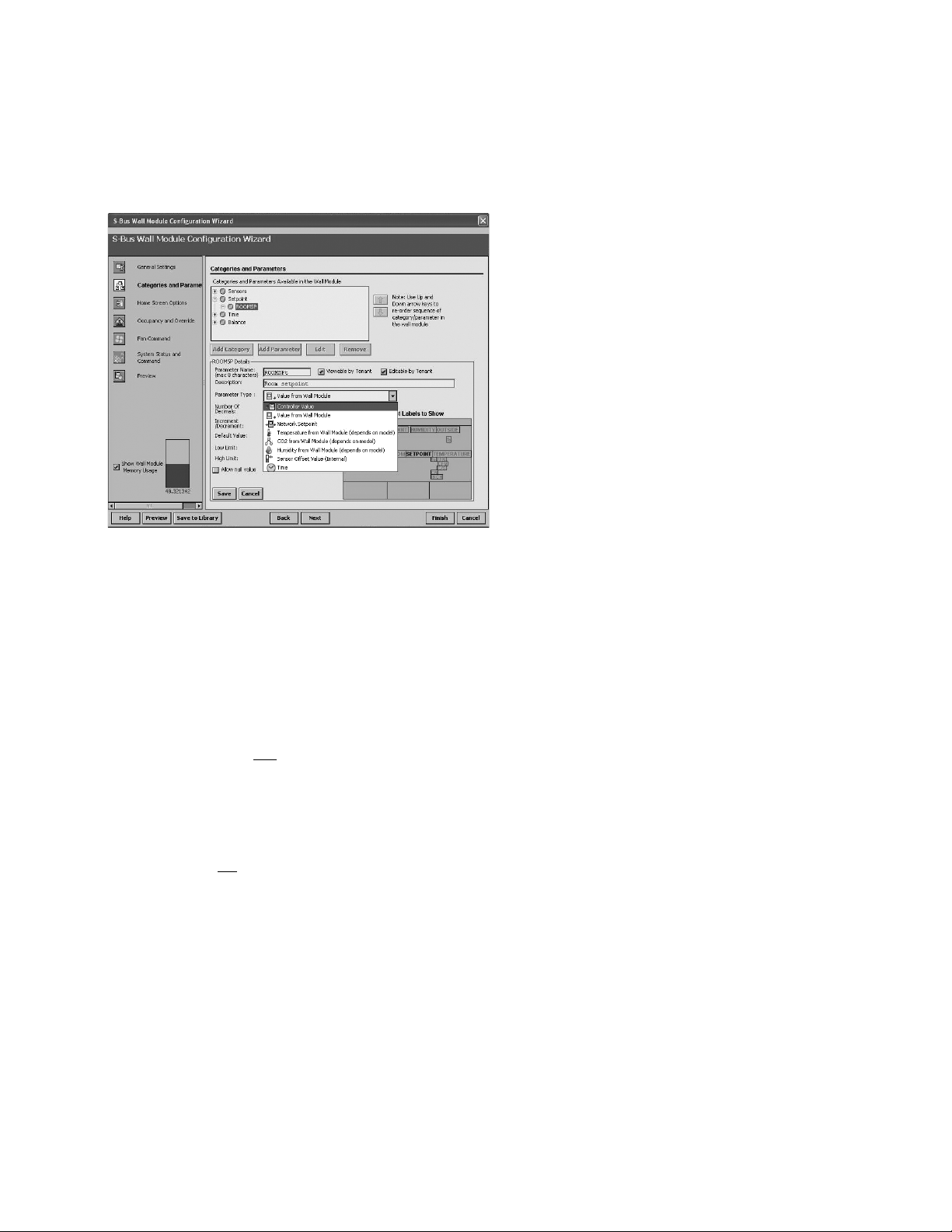
PARAMETER TYPES AND LIMITS
See Fig. 13 for an illustration of the Parameter Type drop
down list. There is a limit to the number of parameters that can
be configured. In addition to the parameter limit, there is also
a memory limit (see “Memory Usage” on page 4).
ZIO™ LCD WALL MODULES
Fig. 13. Parameter Type selection.
The individual parameter maximums are:
— Inputs – up to 30 Controller Values
• These are read-only inputs to the wall module and
include system status and occupancy status, if
configured. Controller Value parameters take up
less memory than other parameters.
— Outputs – up to 19 Values from Wall Module
• These are outputs from the wall module such as
temperature or room setpoint.
— Input/Outputs – up to 10 Network Setpoints
• A network setpoint is a network variable that you
want to view and
change at the wall module.
— Sensors
• 2 sensors (Temperature and Humidity)
•2 Sensor Offset Values (temperature and
humidity)
IMPORTANT
You can not
maximize all of these parameters
together. The size of the data files limits the total
number. If you have more of one type of input or
output, then you must have less of other(s). There
are many combinations possible.
NOTE: Network Variables need to be linked to the
appropriate S-Bus wall module’s function block slots.
See “Link Slots on the Wire Sheet” on page 17 for
details.
Continue with “Home Screen Options” on page 10.
9 63-2667—01
Page 10

ZIO™ LCD WALL MODULES
Home Screen Options
I Home Screen Options
selection from Wizard Menu
Fig. 14, shows the Home Screen Options window and lists the
Home screens currently configured, where you can add, edit,
or remove them.
DEFAULT HOME SCREEN
The current default Home screen always displays at the top of
the list. You can select any item in the list and click the Set As
Default button to change the default Home screen.
NOTE: You can use the Remove button to delete unused
Home screen options to free up memory space.
PREVIEW
The bottom pane, Home Screen Option Preview, displays the
current selected item’s Home screen. When more than one
Home screen is configured, you can click the softkey button
rectangle, below “Next” in the preview pane, to cycle through
all the Home screens in the list.
ADD OR CHANGE HOME SCREENS
Clicking the Add or Edit button displays the Details pane
below the Home screen options tree (see Fig. 15).
You use the Details pane to create or change a Home screen:
•The Option Name item allows you to enter a 1 to 32
character description that displays in the Home Screen
Options Available list.
•The Set as Default selection, if clicked, causes this Home
screen to be the initial Home screen for the wall module
(after the configuration is downloaded to the wall module).
•The Description text you enter displays when you mouse
over any Preview screen.
•Use the Option Type selection to choose either single or
multiple (1 to 3) parameters to display on the Home screen.
• For the Single Parameter option type, there is an
option to display a custom label up to 8 characters
in length.
• In the lower right of the window, you select the desired
Home screen labels for the wall module. The number of
labels is based on your Option Type selection.
• When selecting a parameter to display on the
Home screen, note the maximum number of digits
allowed, which varies from 3 to 4 depending on
where the parameter displays on the LCD.
• Click on the desired label box above each
parameter to choose that label text to display on
the wall module.
• When you complete your Home screen selections, click the
Save button on the lower left of the Details pane.
After you choose the settings, use the Preview at the bottom
left of the wizard window to exercise the Home screen and
cycle through its options.
Wall Module Configuration Wizard
General Settings
Categories and Parameters
Home Screen Options
Occupancy and Override
Fan Command
System Status and
Command
Preview
Show Wall Module
Memory Usage
---
Preview
…
Save to Library
Home Screen Options
Home Screen Options Available for Selection from the Wall Module
Setpoint, Outside, Room (Default)
Room, Outside, Setpoint
Setpoint, Room
Room, Setpoint
Room
Room, Time
Room, Outside, Time
RemoveSet as Default Add Edit
Home Screen Option (Setpoint, Outside, Room) Preview:
ROOM SETPOINT HUMIDITY OUTSIDE
__ __
Cancel
--
ROOM SETPOINT TEMPERATURE
____
NEXT SYSTEM
& VIEW MORE
PARAME TERS
Note: Use ‘Up’ and ‘Down’
arrow keys to re-order
sequence of ‘Home Screen
Options’ in the wall module
X
CancelFinishNext >< BackHelp
M27371
Fig. 14. Home Screen Options.
Wall Module Configuration Wizard
General Settings
Categories and Parameters
Home Screen Options
Occupancy and Override
Fan Command
System Status and
Command
Preview
Show Wall Module
Memory Usage
---
Preview
Home Screen Options
Home Screen Options Available for Selection from the Wall Modul e
Setpoint, Outside, Room (Default)
Room, Outside, Setpoint
Setpoint, Room
Room, Setpoint
Room
Room, Time
Room, Outside, Time
New Home 1
New Home Details
…
Save to Library
Option Name:
Description:
Option Type:
Note: Select the parameter you
want to show from the drop down
lists
New Home 1
Multiple Parameter (Up to Three Values with Fixed Labels)
Single Parameter (One Value with Custom Eight Character Label)
CancelSave
Note: Use ‘Up’ and ‘Down’
arrow keys to re-order
sequence of ‘Home Screen
Options’ in the wall module
RemoveSet as Default Add Edit
Set as Default
Click Boxes to Select Labels to Show
ROOM SE TPOINT HUMIDITY OUTSIDE
NONE
(max 3 digits) (max 3 digits)
Cancel
NONE
--
ROOM SETPOINT TEMPERATURE
NONE
(max 4 digits)
% PPM
AM CFM
PM L/S
CM
INCH
%
CancelFinishNext >< BackHelp
M27495
Fig. 15. Home Screen Details.
If you are finished with your configuration, go to “Preview” on
page 15, otherwise continue with “Occupancy and Override”
on page 11.
X
63-2667—01 10
Page 11

ZIO™ LCD WALL MODULES
Occupancy and Override
STANDARD SETTINGS
Wall Module Configuration Wizard
General Settings
Categories and Parameters
Home Screen Options
Occupancy and Override
Fan Command
System Status and
Command
Preview
Occupancy and Override
Show Advanced Settings
Enable Occupanc y Override
Select the Valid States That You Can Override To:
Occupied (3:00 hours)
Occupancy Status Display Options
Show Effective Occupancy Status
…
Show Occupancy Override Status
Do Not Show Occupancy or Override Status
Occupancy and Override Preview:
I Ocupancy and Override
selection from Wizard Menu
Settings…
Fig. 16, shows the Occupancy and Override options in the
main window for standard and advanced settings. Clicking the
Show Advanced Settings button displays the advanced
settings.
NOTES:
1. The preview at the bottom of the window displays
the occupancy option currently selected.
2. If an Override option is selected, the Override
softkey displays in the preview. Pressing the
Override softkey cycles through the available
override options.
ENABLE OCCUPANCY OVERRIDE
Clicking the Enable Occupancy Override box enables this
feature and also enables the current Occupancy status (3:00
hours as shown in Fig. 16).
ADVANCED SETTINGS
X
Wall Module Configuration Wizard
General Settings
Categories and Parameters
Home Screen Options
Occupancy and Override
Fan Command
System Status and
Command
Preview
Occupancy and Override
Hide Advanced Settings
Enable Occupancy Override
Enable Occupancy Override
Select the Valid States That You Can Override To:
Occupied (Continuous)
Unoccupied (Continuous)
Standby (Min = 1 day, Max = 3 days)
Occupancy Status Display Options
Show Effective Occupancy Status
…
Show Occupancy Override Status
Do Not Show Occupancy or Override Status
Occupancy and Override Preview:
Settings…
Settings…
Settings…
Occupancy Values
Occupied:
Unoccupied:
Bypass:
Standby:
Null:
X
0
1
2
3
255
Show Wall Module
Memory Usage
Preview
Cancel
---
Save to Library
EDIT CANCEL
SETOVE RR IDE
VIEW MORE
--
UNOCCUPIE D
STANDBY
CancelFinishNext >< BackHelp
Fig. 16. Occupancy and Override screens.
OCCUPANCY STATUS DISPLAY OPTIONS
Here you select how the override status displays on the LCD.
The options are:
• Show effective occupancy status – LCD shows the actual
occupancy status taking into account the programmable
controller configuration.
Show Wall Module
Memory Usage
Preview
Cancel
---
Save to Library
EDIT CANCEL
SETOVE RR IDE
VIEW MORE
--
UNOCCUPIE D
STANDBY
CancelFinis hNext >< BackHelp
M27372
• Show occupancy override status – LCD shows the
occupancy override status initiated from the LCD,
independent of the programmable controller configuration.
• Do not show occupancy or override status – LCD does not
show occupancy or override, regardless of what the user
initiates and the programmable controller configuration.
11 63-2667—01
Page 12

ZIO™ LCD WALL MODULES
OVERRIDE SETTINGS
Clicking the Settings button displays the Override to
Occupancy settings pop-up (see Fig. 17), where you can
select Continuous (default) or Timed (hours or days) Override
settings.
TIMED OVERRIDE IN HOURS TIMED OVERRIDE IN DAYS
Override to Occupied Settings
Override to Occupied Settings
Continuous Override
Override Type:
Override Type:
Timed Override Details
Timed Override Details
Use Network Bypass Time Only
Use Network Bypass Time Only
Minimum Time:
Minimum Time:
Days:
Days:
Maximum Time:
Maximum Time:
Days:
Days:
Note: One ‘Day’ is a 24 hour period from the time the override is
Note: One ‘Day’ is a 24 hour period from the time the override is
initiated.
initiated.
Cancel
Continuous Override
Timed Override In Hours (Bypass)
Timed Override In Hours (Bypass)
Timed Override In Days (Bypass)
Timed Override In Days (Bypass)
Minutes:
Hours:
Hours:
Hours:
Hours:
03
03
03 00
03 00
Minutes:
Minutes:
Minutes:
--
CancelOK
CancelOK
00
00
X
X
Override to Occupied Settings
Override to Occupied Settings
Continuous Override
Override Type:
Override Type:
Timed Override Details
Timed Override Details
Use Network Bypass Time Only
Use Network Bypass Time Only
Minimum Time:
Minimum Time:
Days:
Days:
Maximum Time:
Maximum Time:
Days:
Days:
Note: One ‘Day’ is a 24 hour period from the time the override is
Note: One ‘Day’ is a 24 hour period from the time the override is
initiated.
initiated.
Cancel
Continuous Override
Timed Override In Hours (Bypass)
Timed Override In Hours (Bypass)
Timed Override In Days (Bypass)
Timed Override In Days (Bypass)
Hours:
01
01
01
01
Hours:
Hours:
Hours:
CancelOK
CancelOK
--
Minutes:
Minutes:
Minutes:
Minutes:
X
X
Fig. 17. Override to Occupied Settings (Hours or Days).
Clicking the Timed Override in Hours/Days boxes enable the
Override details where you can enter the desired override
timings.
Clicking the Use Network Bypass Time Only box disables all
other override details. The timed override details will be
determined by the programmable controller configuration.
This option only applies to Occupancy override settings.
Unoccupied and Standby do not use bypass.
ADVANCED SETTINGS
When the Show Advanced Settings button is clicked,
overrides to Occupied, Unoccupied, and Standby options are
possible.
M27496
The Override to Unoccupied selection’s Settings button
displays pop-ups similar to the Override to Occupied Settings
shown in Fig. 17, but the timings apply to Unoccupied status.
NOTE: The Override to Unoccupied Settings does not have
a Network Bypass option.
If you are finished with your configuration, go to “Preview” on
page 15, otherwise continue with “Fan Command” on
page 13.
63-2667—01 12
Page 13

Fan Command
ZIO™ LCD WALL MODULES
Fig. 18, shows the Fan Command options in the main window
for standard and advanced settings. Clicking the Show
Advanced Settings button displays the advanced settings.
I Fan Command selection from
Wizard Menu
Wall Module Configuration Wizard
General Settings
Categories and Parameters
Home Screen Options
Occupancy and Override
Fan Command
System Status and
Command
Preview
Show Wall Module
Memory Usage
---
Preview
…
Fan Command Preview:
Save to Library
Fan Command
Show Advanced Settings
Enable Fan Command
Select the Valid Fan States:
2 State (On / Auto)
3 State (On / Off / Auto)
5 State (Off / Auto / Low / Medium / High)
Default Fan State:
On
Cancel
AUTO
ON
PREV DONE
SET FAN
HOME S C RE E N
CancelFinishNext >< BackHelp
Fig. 18. Fan Command screens.
Clicking the Enable Fan Command box enables the fan state
value selections.
The default Fan Command option is: 2 State (On / Auto). The
default for the Fan State is selectable.
STANDARD SETTINGS
Wall Module Configuration Wizard
X
General Settings
Categories and Parameters
Home Screen Options
Occupancy and Override
Fan Command
System Status and
Command
Preview
Show Wall Module
Memory Usage
---
Preview
…
Fan Command Preview:
Save to Library
Fan Command
Hide Advanced Settings
Enable Fan Command
Select the Valid Fan States:
2 State (On / Auto)
3 State (On / Off / Auto)
5 State (Off / Auto / Low / Medium / High)
Default Fan State:
On
Cancel
AUTO
ON
PREV DONE
SET FAN
HOME S C RE E N
Fan Status Values
Off:
On:
Auto:
Low:
Medium:
High:
After you choose the setting, use the Fan Command Preview
at the bottom of the window to exercise the Fan softkey to
cycle through the options.
ADVANCED SETTINGS
X
0
1
2
3
4
5
CancelFinishNext >< BackHelp
M27373
Table 3. Fan State Values.
Selectable
Fan State Fan State Values
2 State On / Auto
3 state On / Off / Auto
5 State Off / Auto / Low / Medium / High
• Low, medium, and high are the three
states of the fan speed indicator triangle.
See Fig. 27 on page 22 for an example.
If you are finished with your configuration, go to “Preview” on
page 15, otherwise continue with “System Status and
Command” on page 14.
13 63-2667—01
Page 14

ZIO™ LCD WALL MODULES
System Status and Command
I System Status and
Command selection from
Wizard Menu
Fig. 19 shows the System Status and Command options in the
main window. Clicking the Show Advanced Settings button
displays the advanced settings.
Wall Module Configuration Wizard
General Settings
Categories and Parameters
Home Screen Options
Occupancy and Override
Fan Command
System Status and
Command
Preview
Show Wall Module
Memory Usage
---
Preview
System Status and Command
Show Advanced Settings
Show System Status
Enable System Command
Select the Valid System Commands:
Off / Heat (Heat Only)
Off / Cool (Cool Only)
Off / Heat / Cool (No Auto Changeover)
Off / Auto / Heat / Cool (Auto Changeover)
Off / Auto / Heat / Cool / Emergency Heat (Heat Pump)
…
Default System Command:
System Status and Command Preview:
Save to Library
Heat
SYSTEM: OFF AUTO COOL EM. HEAT
Cancel
--
NEXT SYSTEM
& VIEW MORE
PARAME TERS
CancelFinishNext >< BackHelp
Fig. 19. System Status and Command screen.
Clicking the Show System Status box enables the System
Status line including the snowflake (cool) and flame (heat)
icons and the System softkey on the LCD as shown in the
Preview area at the bottom of the screen.
The System softkey on the LCD is enabled only when the
Enable System Command option is selected.
The Enable System Command selections control the values
that display on the System Status line at the top of the wall
module’s LCD screen.
The default System Command option is: Off / Heat (Heat
Only). The default for the System State is selectable.
STANDARD SETTINGS
Wall Module Configuration Wizard
X
General Settings
Categories and Parameters
Home Screen Options
Occupancy and Override
Fan Command
System Status and
Command
Preview
Show Wall Module
Memory Usage
---
Preview
System Status and Command
Hide Advanced Settings
Show System Status
Enable System Command
Select the Valid System Commands:
Off / Heat (Heat Only)
Off / Cool (Cool Only)
Off / Heat / Cool (No Auto Changeover)
Off / Auto / Heat / Cool (Auto Changeover)
Off / Auto / Heat / Cool / Emergency Heat (Heat Pump)
…
Default System Command:
System Status and Command Preview:
Save to Library
Heat
SYSTEM: O FF AUT O COOL EM. HE AT
Cancel
--
NEXT SYSTEM
& VIEW MORE
PARAME TERS
System Status Values
Off:
Heat:
Cool:
Reheat:
System Command Values
Off:
Auto:
Heat:
Cool:
Emergency:
Table 4. System State Values.
Selectable System States
Off / Heat (Heat Only)
Off / Cool (Cool Only)
Off / Heat / Cool (No Auto Changeover)
Off / Auto / Heat / Cool (Auto Changeover)
Off / Auto / Heat / Cool / Emergency Heat (Heat Pump)
After you choose the setting, use the Preview button at the
bottom of the window to verify your configuration.
To review your configuration, continue with “Preview” on
page 15.
ADVANCED SETTINGS
X
0
9
2
7
0
1
2
3
4
CancelFinishNext >< BackHelp
M27374
63-2667—01 14
Page 15

Preview
ZIO™ LCD WALL MODULES
Fig. 20 shows your current configuration of the wall module
Home screen. You can select either the Tenant or Contractor
view. The three softkeys in the preview LCD display are
interactive and function just like the ones on the physical wall
module display.
I Preview selection from
Wizard Menu
Preview is a great way to verify all your configuration and
setup parameters to ensure that they work exactly the way
you want them to function.
Preview simulates the actual wall module interface and allows
you to verify the operation of the current configuration of the
wall module. Clicking on the three softkey rectangles below
the labels of the preview display exercises the features you
have configured.
NOTE: Since the up and down arrow keys do not display in
Preview mode, no adjustments to parameters (e.g
setpoint temperature) can be made.
Wall Module
General Settings
Categories and Parameters
Home Screen Options
Occupancy and Override
Fan Command
System Status and
Command
Preview
Show Wall Module
Memory Usage
---
Preview
Select View:
…
Tenant View
SYS TE M: OFF AUTO COOL E M. HE AT
Cancel
Cool
AUTO
ON
PREV DONE
SYSTEM: OFF AUTO COOL E M. HEAT
SET FAN
HOME S C RE E N
EDIT CANCEL
SET OVERRIDE
VIEW MORE
Contractor View
HUMIDITY OUTS IDE
__
--
NEXT S YS TEM
& VIEW MORE
PARAME TERS
Off:
Auto:
Heat:
Cool:
UNOCCUPIED
STANDBY
CancelFinishNext >< BackHelp Save to Library Preview
M27375
Fig. 20. Preview screen.
To complete the configuration, continue with “Completing the
Setup and Configuration” on page 16.
X
15 63-2667—01
Page 16

ZIO™ LCD WALL MODULES
Completing the Setup and Configuration
For custom configurations, begin with “Custom Configurations
Only”, otherwise continue with “All Configurations”.
Custom Configurations Only
If you are customizing a configuration, use the Save to Library
button to save your configuration. Clicking the button displays
a pop-up window as illustrated in Fig. 21.
Save Library Item
Block Type:
Wall Module Model
Library:
Parent Folder Path:
Application Details
Wall Module Types:
Model Options:
Overwrite App (new version) Save as New App
Model Selection:
Name:
Wall Module Address:
Type:
…
Temperature Units:
Version:
Select Application:
Description:
Selected Model (TR70-
Attachment:
WalModule
AppLib
Temperature, Humidity, CO2
Local:|file:/c:/niagara
New Custom Application
1
Wall Module Application
°F - Degrees Fahrenheit
1
New Custom Application
Click customize if you want to view or modify
how the LCD display model is configured
Model Capabilities:
-
-2-wire (Sensor Bus) communication
-Configurable LCD display
-Navigation keypad
-Scroll keypad
-LON network jack
-Honeywell logo
Browse…
LCD display
2 wire wall module bus
TR70-
RemoveAdd
X
All Configurations
To complete the configuration process, perform the following
sections in this order:
1. “Preview”
2. “Confirm Memory Usage is within Limits”
3. “Finish the Configuration”
4. “Link Slots on the Wire Sheet” on page 17
5. “Download Configuration Logic to Controller” on
page 19
Preview
Use the Preview button or Preview menu selection to see how
the wall module LCD screen will operate for your selected
configuration (see “Preview” on page 15).
Confirm Memory Usage is within Limits
Check the memory usage bar to make sure your configuration
is within the memory limits of the wall module. See the lower
left corner of Fig. 8 on page 7 for an illustration. Right clicking
on the memory bar displays details about current memory
usage. If necessary, go back and remove unneeded
categories, parameters, or Home screens.
Finish the Configuration
Click the Finish button to commit all your changes to the
database, close the Configuration Wizard, and return to the
wire sheet.
Advanced SettingsHelp
CancelOK
Fig. 21. Save to Library screen pop-up.
M27376
63-2667—01 16
Page 17

ZIO™ LCD WALL MODULES
Link Slots on the Wire Sheet
This section describes how parameters may be linked to the
wall module. Refer the user to the Spyder User Guide, form
63-2662, for more specific information on variables and wire
sheet logic.
The S-Bus Wall Module function block can be dropped into
existing applications to replace the Conventional Wall Module
block. You can see an example in Fig. 22.
When making links from existing blocks to the wall module
function block input slots, there is no need to break the
existing links from these existing blocks. The new tool allows
for multiple output connections.
When connecting to slots on function blocks which lie on
different wire sheets, remember that you can save time by
using the Link Mark method, a standard Niagara Workbench
linking mechanism.
Fig. 22. Example of the S-Bus Wall Module block dropped into a Venom VAV application.
17 63-2667—01
Page 18

ZIO™ LCD WALL MODULES
Viewing the List of Network Variables
This section describes how to view the Network Variables.
1. Browse to Station > Config > Drivers > LonNetwork >
LonSpyder.
2. Select ControlProgram > Views > NV Configuration
View. The summary page appears with a list of preprogrammed Mandatory, Fixed, and Custom NVs in a
tabular format. The table has the following columns:
• NV Name: The name of the network variable.
• Type: Indicates if the NV is of type NVI, NVO, NCI
or Many to One NV.
• Category: Indicates if the NV is Mandatory, Fixed,
or Custom.
• NV Container: Indicates where the NV is used.
3. The bottom half of the NV Configuration view displays
the software points available on the wire sheet in a
tabular format. The table has the following columns:
• Point Name: The name of the software point
(Software Input/Software Output) as it appears on
the wire sheet.
• Field Names: Indicates if the NV is of type NVI,
NVO, NCI or Many to One NV.
• Point Container: Indicates where the software point
is used. All software points that are used in a
Program within an application are also listed.
NOTES:
— Mandatory NVs cannot be used in the application
logic.
— Mandatory NVs cannot be edited or deleted.
— In a Fixed NV, only Internal Data Type can be
modified.
— Custom NV is the user defined NV. A Custom NV
can be edited or deleted.
— Fixed NVs marked as Fixed_Dropable can be
exposed on the wire sheet. Other fixed NVs
cannot be exposed as points.
— For each point that is copied and pasted on the
wire sheet, a new NV of SNVT type nearest to the
selected data type is created automatically.
63-2667—01 18
Page 19

Download Configuration Logic to Controller
This section describes how to download the configuration into
the Sylk Enhanced Spyder Controller. Refer to the appropriate
programmable controller user guidea for additional detail.
To download the configuration logic to a programmable
controller:
1. Right click the device and select Actions > Download as
shown in Fig. 23.
2. The Download dialog box displays as a pop-up. Click
OK to download the logic to the controller as shown in
Fig. 24.
ZIO™ LCD WALL MODULES
Fig. 24. Download to programmable controller (step 2).
Fig. 25 and Fig. 26 beginning on page 21 illustrate the
download actions of the Niagara workbench application.
Fig. 23. Download to programmable controller (step 1).
a
Refer to the Honeywell Spyder User’s Guide (form 63-2662)
or the ComfortPoint Programmable Controller User’s Guide
(form 63-2663) depending on the programmable controller
used.
19 63-2667—01
Page 20

ZIO™ LCD WALL MODULES
Fig. 25. Begin actual download to programmable controller.
63-2667—01 20
Page 21

ZIO™ LCD WALL MODULES
Fig. 26. Complete actual download to programmable controller.
Download Configuration to the Wall Module
Whenever the wall module is powered, it communicates with
the programmable controller every several seconds and
uploads/downloads any new or changed configuration/
parameter information.
This completes the configuration process for installation.
M27497
21 63-2667—01
Page 22

ZIO™ LCD WALL MODULES
OPERATING THE ZIO WALL MODULE
There are two modes of operation:
• Contractor mode provides features a contractor would use
such as selecting the Home screen, selecting parameters
the tenant can view, and monitoring/modifying controller
parameters, which includes balancing.
• Tenant mode provides features a tenant would use such
as changing the setpoint, fan speed or system mode,
initiating override, or monitoring/modifying permitted
controller parameters. See page 24 for information about
Tenant Mode operation.
Contractor Mode (Entering and Exiting)
Contractor mode allows access to the Setup function of the
wall module.
To enter and exit the Setup function – Press the Up and Down
arrow keys and the middle softkey all at the same time (see
Fig. 1 on page 1 for key positions).
Contractor Mode Operation
Contractor mode allows advanced options (such as modifying
configured parameters) using the softkeys. Contractor mode
also allows for customizing the tenant’s view including setting
the tenant’s Home screen and controlling the tenant’s “View
More” access, which can provide the tenant with a view of the
configured parameters.
Contractor Home Screen Softkeys
• Clicking the NEXT softkey cycles through the
configured
• Click the DONE softkey when the desired Home
screen displays.
• The CANCEL softkey exits the Home screen
display without saving any changes.
Fig. 28. Sample Contractor display showing
SET VIEW MORE allows the contractor to provide parameter
access (view only or adjustable) to the tenant’s VIEW
MORE softkey.
• Clicking the VIEW MORE softkey displays the first
configured parameter as shown Fig. 29, and the
softkeys change to DONE, CANCEL, and NEXT.
• The Up and Down arrow keys switch the parameter
between YES and NO (view or no view in Tenant
Mode). YES means that the tenant has access to
the parameter in the View More screen. NO means
the tenant does not have access to the parameter.
• If NO is selected for all
MORE softkey does not display in tenant mode.
• The NEXT softkey moves to the next parameter or
category.
• Click the DONE softkey when finished.
• The CANCEL softkey exits VIEW MORE without
saving any changes.
a
Home screens.
Home screen setup.
parameters, then the VIEW
M27378
M27357
Fig. 27. Typical Contractor LCD display.
The three softkeys on the contractor Home screen (see
Fig. 27) provide the following:
SET HOME SCREEN allows the contractor to choose among
multiple Home screen options for the tenant.
The tenant’s Home screen choices are created by the
Configuration Wizard and downloaded to the wall module.
Each wall module may have different Home screen
choices. The contractor, using the softkeys, may choose
which Home screen should be used, and may configure
the Tenant view to show a subset (or none) of the
configured parameters.
• When the contractor clicks the SET HOME
SCREEN softkey, The display changes as shown in
Fig. 28, and the softkeys change to DONE,
CANCEL, and NEXT.
63-2667—01 22
Fig. 29. Set View More parameter display.
a
See “Home Screen Options” on page 10.
Page 23

ZIO™ LCD WALL MODULES
PARAMETERS allows the contractor to monitor and/or adjust
parameters in the programmable controller.
• Clicking the PARAMETERS softkey displays the
first configured category as shown in Fig. 29, and
the softkeys change to DONE, EDIT, and NEXT.
• When clicked, the EDIT softkey drops you into the
parameter list for the displayed category and
displays the first parameter in that category (e.g.
the HUMIDITY parameter in the SET PNTS
category as shown in Fig. 30).
• If the parameter has been configured as adjustable
by the tenant, the Up and Down arrow keys adjust
the value of the parameter.
• The NEXT softkey displays the next parameter or
category.
• Click the DONE softkey when finished.
Sample Contractor LCD Displays
The contractor mode allows advanced options using the
softkeys. Contractor mode also allows for customizing the
Tenant view including setting the tenant’s Home screen and
View More access.
The LCD display may be customized for the contractor. This
section includes three examples of the various contractor
Home and Parameter screens that are configurable for the
LCD Wall Module. Not all possible screens are illustrated
here. There are many other configurable screens.
M27357
Fig. 31. Sample Contractor Home screen display with
System Status, Setpoint, Outside Temperature,
and Room Temperature (predominant).
Fig. 30. Parameter display showing editing sequence.
M27358
Fig. 32. Sample Contractor parameter display showing a
user-created discharge air parameter value.
M27359
Fig. 33. Sample Contractor parameter display showing
sensor setpoint value (CO
sensor from controller).
2
NOTE: Any configured parameter may be displayed.
23 63-2667—01
Page 24

ZIO™ LCD WALL MODULES
Tenant Mode Operation
The tenant, using the softkeys and arrow keys, may change
the setpoint, fan speed, system mode (heat/cool), or initiate
override, if these features are configured. The tenant may
change the Occupancy Override parameter to Occupied,
Unoccupied, or Standby. And, the override can be timed in
minutes, days, or be continuous.
M27354
Fig. 34. Typical Tenant LCD display.
TENANT HOME SCREEN SOFTKEYS
As shown in Fig. 34, there can be three softkeys configured
for the tenant’s Home screen – FAN, OVERRIDE, and
SYSTEM & VIEW MORE.
NOTES:
1. The Fan and Override settings are optional for
Home screen setup.
2. If the System Command option is not enabled,
then the SYSTEM softkey does not display on the
tenant’s Home screen.
3. If there are no parameters configured for tenant
access, the VIEW MORE softkey does not display
on the tenant’s Home screen.
FAN allows the tenant to adjust the fan settings depending on
the fan options (2, 3, or 5 position) configured.
As shown in Fig. 35, each click of the FAN softkey changes
the fan icon display between:
• 2 position: ON and AUTO
• 3 position: OFF, AUTO, and ON
• 5 position: OFF, AUTO, and the three states of the fan
speed indicator (low, medium, and high)
OVERRIDE allows the tenant to override the Occupancy
settings (see Fig. 36).
• Depending on the occupancy/override
configuration, each click of the OVERRIDE softkey
changes the occupancy icon displays between
STANDBY, OCCUPIED, and UNOCCUPIED.
• If an override is set by the tenant, the OVERRIDE
softkey changes to CANCEL OVERRIDE.
• Clicking the CANCEL OVERRIDE softkey cancels
the override.
Fig. 36. Override display for Tenant.
SYSTEM & VIEW MORE Depending on the configuration,
this softkey allows the tenant to change the system state
and view/adjust configured parameters (see Fig. 37).
• The first click displays the system information and the
Up and Down arrow keys change the system state
between OFF, AUTO, COOL, HEAT, and EM.HEAT
(emergency heat).
• Clicking the VIEW MORE/NEXT softkey displays each
viewable parameter.
• If the contractor enables tenant access to a parameter,
then the tenant can use the Up and Down arrow keys
to adjust the parameter’s value, otherwise the tenant is
able to only view the parameter and its value.
NOTE: When the contractor configures a parameter and
selects the Editable by Tenant check box, this
enables the tenant to adjust the parameter’s value.
See Fig. 13 on page 9 for an example.
• Click the CANCEL softkey to exit the display without
saving any changes.
• Click the DONE softkey when finished.
Fig. 35. Fan display for Tenant showing 5-position setting
with fan at medium speed.
63-2667—01 24
Fig. 37. System and View More display for Tenant.
Page 25

Tenant Home Screen Display
The LCD display may be customized for the tenant. This
section includes a few examples of the various tenant Home
screens that are configurable for the LCD Wall Modules. Not
all possible Home screens are illustrated here. There are
many other configurable Home screens.
NOTE: Home screens can display one to three of any of the
following parameters: temperature setpoint, room
temperature, room humidity, outdoor humidity, and
outdoor temperature, and time, or one of virtually any
parameter in the controller.
SAMPLE TENANT HOME SCREEN DISPLAYS
Figures Fig. 38 through Fig. 43 illustrate typical tenant home
screens.
ZIO™ LCD WALL MODULES
M27355
Fig. 40. Sample Tenant Home screen with Humidity and
Room Temperature (predominant).
M27352
Fig. 38. Sample Tenant Home screen with Room
Temperature and Setpoint (predominant).
The Fan and Occupied settings are optional for Home screen
setup. If there are no parameters configured for tenant
access, the “View More” softkey does not display on the
tenant’s Home screen.
M27354
Fig. 39. Sample Tenant Home screen with System Status,
Setpoint, Outside Temperature, and
Room Temperature (predominant).
M27379
Fig. 41. Sample Tenant Home screen with Room
Temperature and Time (predominant).
NOTE: In Fig. 41, there are no Fan, System, or View More
softkey options configured for this Home screen.
M27498
Fig. 42. Sample Tenant Home screen with a single,
custom parameter.
NOTE: In Fig. 42, the Home screen is configured with only a
single, custom parameter. See “Preview” on
page 10.
25 63-2667—01
Page 26

ZIO™ LCD WALL MODULES
M27356
Fig. 43. View More display showing CO2 sensor value
from controller.
NOTE: As shown in Fig. 43, any configured parameter may
be displayed to the tenant.
63-2667—01 26
Page 27

ZIO™ LCD WALL MODULES
27 63-2667—01
Page 28

ZIO™ LCD WALL MODULES
ComfortPoint™ is a trademark of Honeywell International Inc.
Spyder™ is a trademark of Honeywell International Inc.
Sylk™ is a trademark of Honeywell International Inc.
Zio™ is a trademark of Honeywell International Inc.
By using this Honeywell literature, you agree that Honeywell will have no
liability for any damages arising out of your use or modification to, the
literature. You will defend and indemnify Honeywell, its affiliates and
subsidiaries, from and against any liability, cost, or damages, including
attorneys’ fees, arising out of, or resulting from, any modification to the
literature by you.
Automation and Control Solutions
Honeywell International Inc. Honeywell Limited-Honeywell Limitée
1985 Douglas Drive North 35 Dynamic Drive
Golden Valley, MN 55422 Toronto, Ontario M1V 4Z9
customer.honeywell.com
® U.S. Registered Trademark
© 2008 Honeywell International Inc.
63-2667—01 M.S. 10-08
 Loading...