

Honeywell TH108PLUS Owners Manual
TH108PLUS
Non-programmable Thermostat
Owner’s
Guide
400-108-015-B 2009-11-30
Owner’s Guide 400-108-015-B
Table of contents
Overview
About your new thermostat ................................................................................... 1
Controls and display.............................................................................................. 2
Installation
Installation guidelines ............................................................................................ 3
Mounting the thermostat ....................................................................................... 4
Wiring .................................................................................................................... 5
Configuration switches .......................................................................................... 6
Operation
Temperature display and setting ........................................................................... 7
Setup menu........................................................................................................... 8
Appendices
In case of difficulty................................................................................................. 9
Specifications ...................................................................................................... 10
3-year limited warranty .........................................................................................11
Customer assistance........................................................................................... 12

TH108PLUS
About your new thermostat
This thermostat is designed to control an electric heating system such as a
baseboard heater, a convector or a fan-forced heater.
The thermostat CANNOT be used with:
• a resistive load under 2 A
• a resistive load over 12.5 A
• a system driven by a contactor or a relay (inductive load)
• a central heating system
SUPPLIED PARTS
• One (1) thermostat
• Two (2) 6-32 mounting screws
• Two (2) solderless connectors
Do you need assistance?
We are here to help.
Call 1-800-831-2823.
1
Owner’s Guide 400-108-015-B
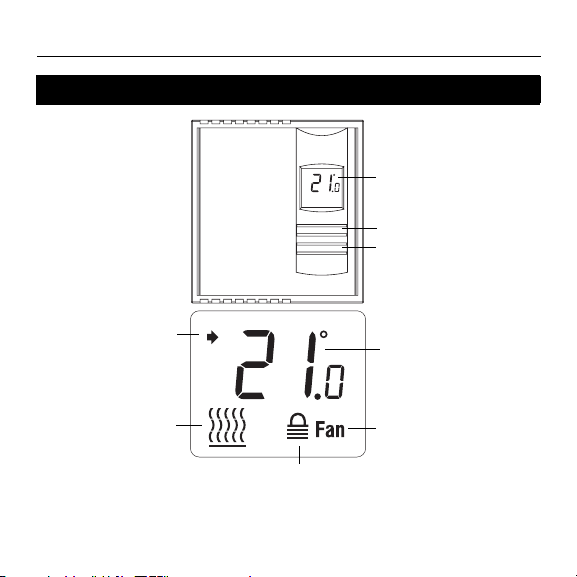
Controls and display
Appears when the
setpoint is displayed
Heating intensity
indicator (the image
disappears when
heating is off)
The settings are locked
(see page 6)
2
Backlit Screen
Up button
Down button
Temperature
Appears when the
thermostat is configured
for a fan-forced heater
(see page 6)

TH108PLUS
Installation guidelines
TURN OFF POWER TO THE HEATING SYSTEM AT THE MAIN POWER
PANEL TO AVOID ELECTRICAL SHOCK.
The installation must be performed by a qualified electrician and must com-
ply with electrical codes of your region.
Do NOT install the thermostat in an area where it can be exposed to water
or rain.
Avoid locations where there are air drafts (such as the top of a staircase or
an air outlet), dead air spots (such as behind a door), or direct sunlight.
Do not install the thermostat on a wall section that conceals air ducts, chim-
ney pipes or stove pipes.
Install the thermostat about 1.5 m (5 feet) high, on an inside wall facing the
heater.
Install the thermostat onto an electrical box.
This thermostat has tinned copper wires for line and load connections. Spe-
cial CO/ALR solderless connectors must be used if the thermostat will be
connected to aluminium wires.
The thermostat wires are not polarized; either wire can be connected to the
load or to the power supply.
Keep the air vents at the top and bottom of the thermostat clean and free
from obstructions.
3
Owner’s Guide 400-108-015-B
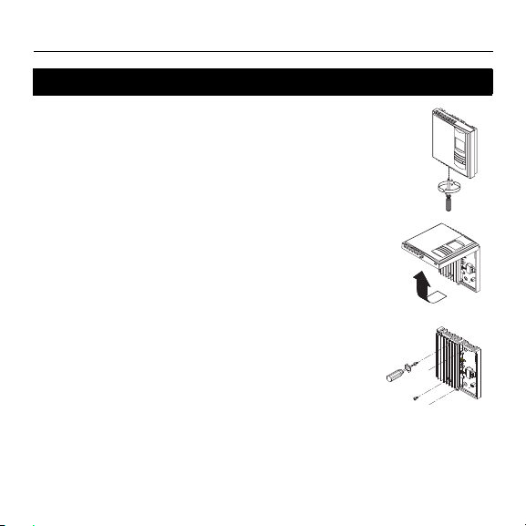
Mounting the thermostat
n Loosen the screw underneath the thermostat and
separate the faceplate from the wallplate.
NOTE: The screw remains captive and cannot be
completely removed.
o Wire the thermostat (see page 5).
p Mount the wallplate to the electrical box using the
provided screws. Insert the screws through the two
left or right mounting holes of the wallplate.
q Set the configuration switches (see page 6)
r Reinstall the faceplate onto the wallplate and tighten
the screw.
NOTE: If there is a protective film or sticker on the
thermostat’s screen, peel it off.
s Apply power to the heating system. Verify the
installation by checking that the heating system can
be turned On by raising the setpoint using the Up
button or turned Off by lowering the setpoint using
the Down button.
4
TH108PLUS
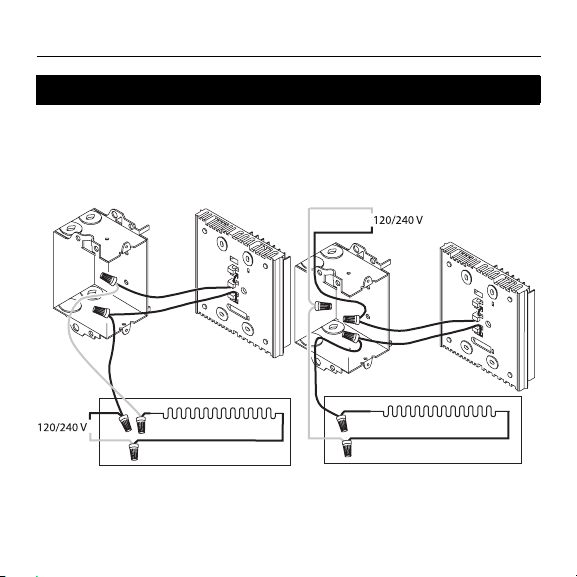
Wiring
Connect the thermostat wires to the heating system (load) and
to the power supply.
2-wire Installation
4-wire Installation
5
Owner’s Guide 400-108-015-B
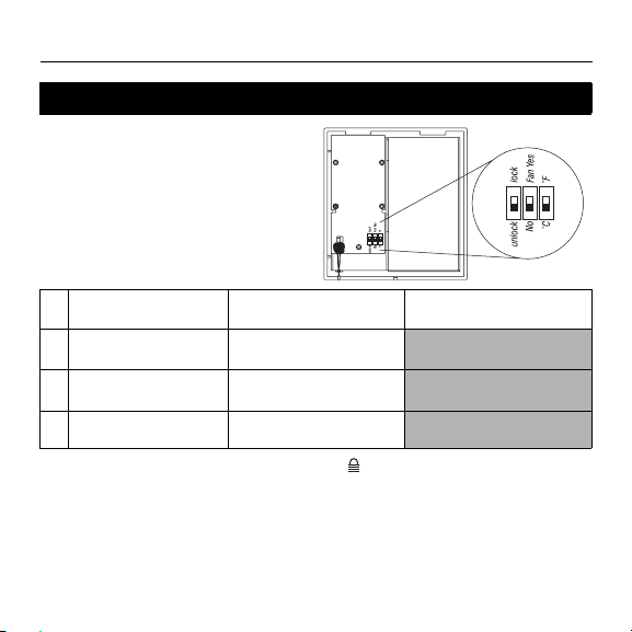
Configuration switches
Configuration switches are on the back
of the faceplate. Factory settings are
inside gray cells.
# Parameter Up Down
1
Settings lock
2
Fan-forced heater
1
2
Lock Unlock
Fan Yes No
3Unit °F
1
The thermostat buttons are disabled and appears on the screen (see page
2) when the settings are locked.
2
Place at Fan Yes if you have a fan-forced heater (to prevent premature burnout of the motor). Leave at No for better temperature regulation if you do not
°C
have a fan-forced heater.
6

TH108PLUS
Temperature display and setting
The thermostat generally displays the room temperature.
• To display the set temperature (setpoint), press the Up or
Down button once. The setpoint temperature will remain on
the screen for 5 seconds.
• To change the setpoint temperature, press the Up or Down
button repeatedly until the desired temperature is displayed.
• The screen is backlit for 10 seconds when any button is
pressed.
7
 Loading...