

Page 1
6I Solenoid valves
Solenoid valve operating methods
D
irect-acting
For small nominal diameters
No minimum differential pressure
required.
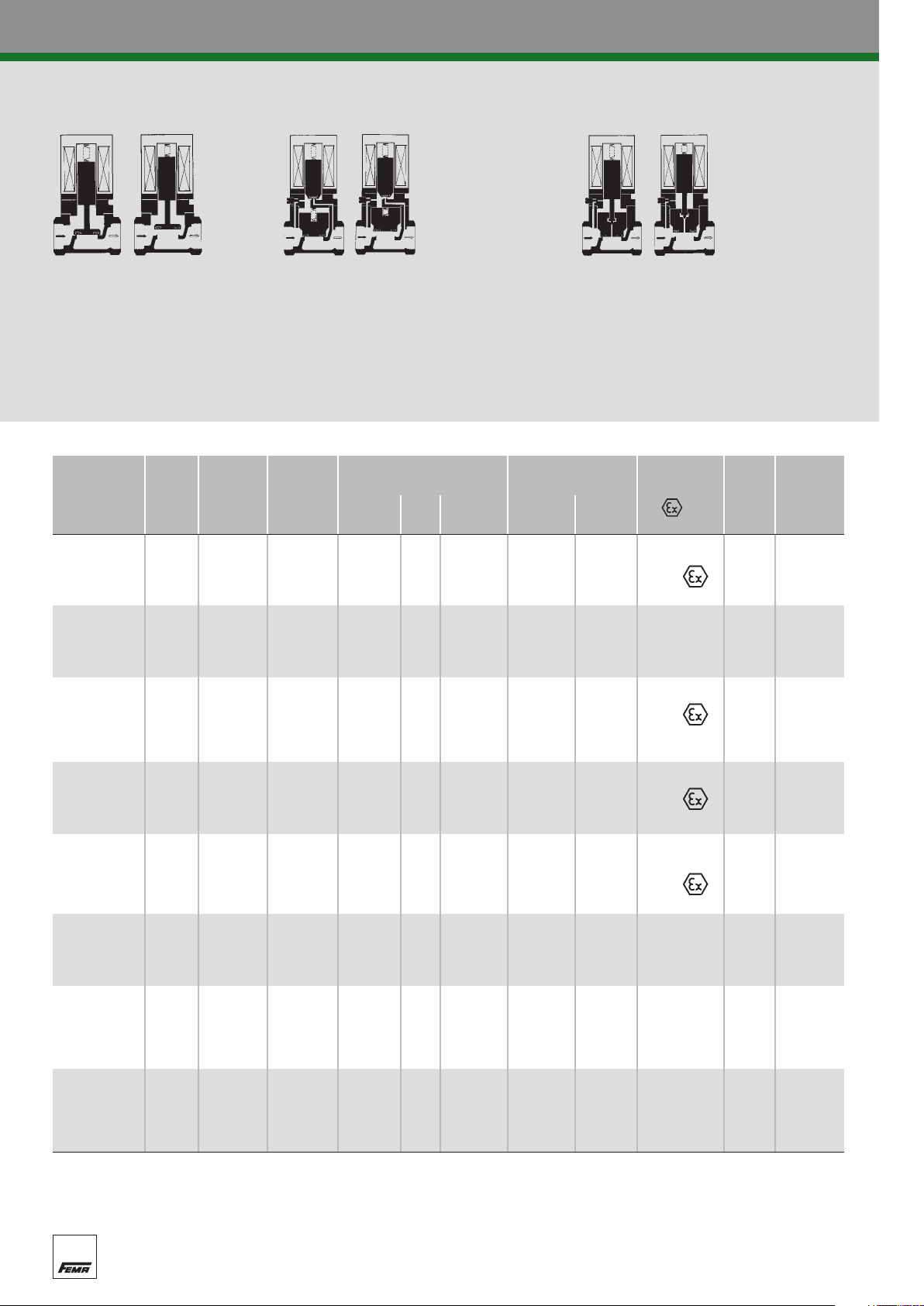
Fema piston-type solenoid valves are suitable for demanding applications, particularly in the field of heat, energy and gas technology.
All valves of the product groups mentioned below are automatically servo-assisted and may therefore be used from 0 bar to maximum
pressure. No minimum differential pressure is required. A DC coil is normally used. A rectifier is supplied for connection to a 230 VAC supply.
Product Summary
Series
Application
Nom. M= Working Seals Temperatures N = Normal Ope- DIN
diame- screwed pressure* Medium Environ- type rating- testing
ter DN F= Piston Noz- Static ment = mode agency
(mm) flange (bar) zle seal °C °C Ex-type
s
ervo-assisted
A minimum differential pressure of approx.
0.5 bar is required. Cannot open without
differential pressure between input and output.
A
utomatically servo-assisted
(coupled) For differential pressures from 0 to
maximum pressure. For universal application.
TG 15/20 M + F 0–40 -15 to -15 to N nc
for neutral 25/32 M + F 0–32 NBR NBR NBR + 90 + 60 + , +
media 40/50 F 0–20 60°C for Ex no
TGK 15/20 M + F 0–40 PTFE Stainl. EPDM max. 180 -15 to N nc
for high 25/32 M + F 0–32 steel + 60 +
temperatures
40/50 F 0–20 cone no
K 15/20 M 0–4 -15 to -15 to N
for fuel 15/20 F 0–4 NBR NBR NBR + 60 + 60 + , nc DVGW
gases up 25/32
to 4 bar 40/50 F 0–4 161
F 0–4 DIN-EN
K 15/20 F 0–25 -15 to -15 to N DVGW
f. fuel gases 25/32
over 4 bar 40/50 F 0–20 part 1
F
0–25 NBR NBR NBR + 60 + 60 + , nc DIN 3394
K TÜV
for liquid 15/20 F 0–25 NBR NBR NBR -15 to -15 to N DIN 32725
gases in 25 F 0–25 + 60 + 60 + , nc (draft
liquid phase Nov ´92)
K 15/20 F 0–25 -15 to 15 to TÜV
for fuel oil 15/32
40/50 F 0–20 264
F 0–25 NBR NBR NBR + 60 + 60 N nc DIN-EN
LG
for hot water 15/20 M + F 0–25 Stainl. + 4 to TÜV
and steam 25/32 M + F 0–20 PTFE steel EPDM max. 120 + 60 N nc DIN 32730
up to 120
C
°
40/50
F
0–16
cone
LGK
for hot water 15/20 M + F 0–20 Stainl. + 4 to TÜV
and steam 25/32 M + F 0–16 PTFE steel EPDM max. 180 + 60 N nc DIN 32730
up to 180
nc = normally closed, opened under voltage.
no = normally open, closed under voltage (identified in the Product Summary by the letter “U”).
*
°C
40/50
espective data sheet contains exact details of the limits of use.
= The r
F 0–12 cone
Sealing materials: NBR = Perbunan
EPDM = Ethylene–propylene rubber
eflon
PTFE
= T
Page 2
Solenoid valves I 7
for universal application
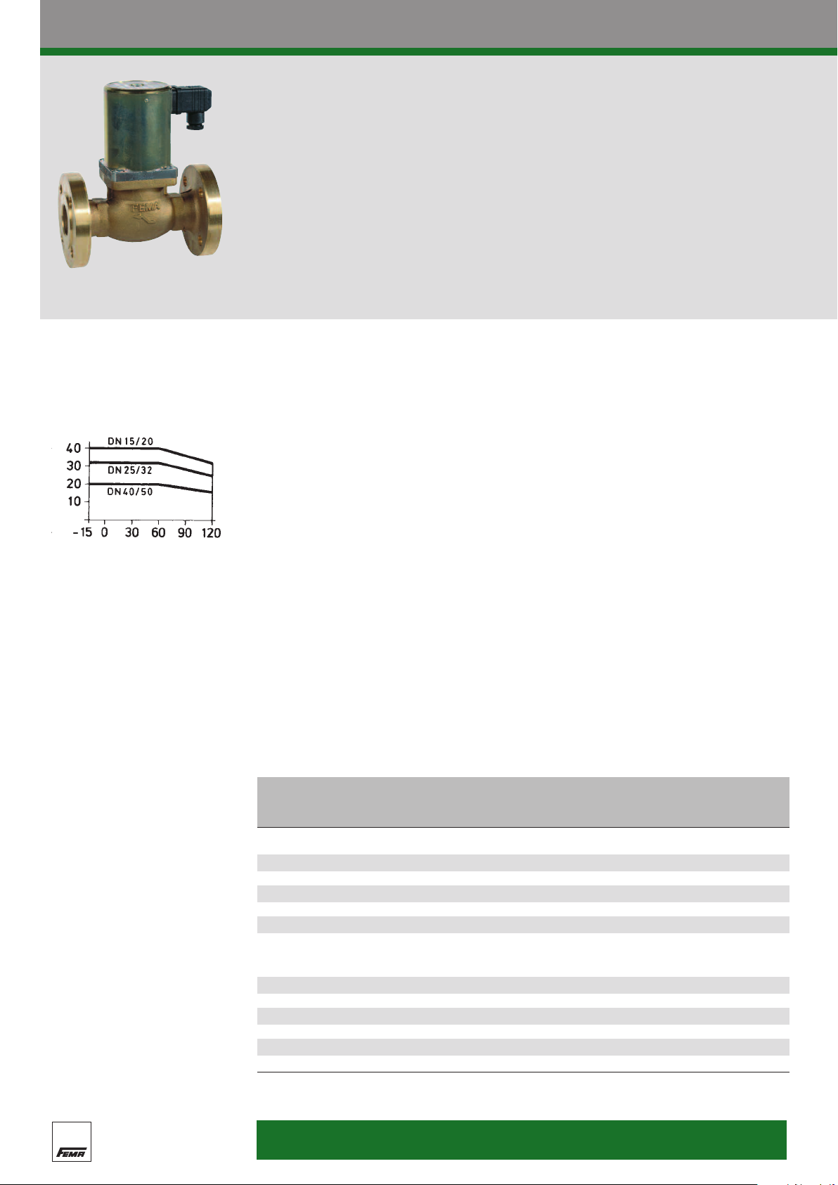
TG series
For medium temperatures up to 90°C
T25G31M
Limits of use
(applies only to the “normally closed”
operating mode)
Perm. working pressure (bar)
Medium temperature (°C)
NB:
To avoid heat build-up, the
solenoid system must not be
insulated or painted.
The piston-type solenoid valves of the TG series
a
re suitable for universal application under
a wide range of pressures. The coupled
(automatically servo-assisted) method of
Technical data
Type
Operating mode Normally closed (standard version) or normally open (on request)
ype of construction
T
Materials Casing: Bronze Rg 5 to DIN 1705
Sealing materials Piston: Perbunan (NBR).
Mounting position Solenoid system preferably upright. Horizontal mounting position
Outdoor installations fr = suitable for outdoor use
Ambient temperature -15°C to +60°C
Temperature of medium -15°C to +90°C
Flanges To DIN 2501 Part 1
Recommended weld-on flanges PN 40 to DIN 2635
Maintenance The valve should be operated 5-10 times per month to prevent
2/2-way
Piston-type solenoid valve, coupled
no minimum differential pressure required
nal parts: Brass (CuZn) and corrosion-resistant steel
Inter
Nozzle: Perbunan (NBR).
Static seal: Perbunan (NBR).
only permitted for DN 15–DN 32. In general, the solenoid system
should not hang downwards.
PN 40 for DN 15–32
PN 25 for DN 40/50
the piston from sticking. No further maintenance is required.
operation requires no minimum differential
p
ressure; the valves open and close without
difficulty even without pressure or with low
differential pressures.
Product Summary
DN kvsvalue Working Screwed Flange
3
(mm)
TG series (up to 90°C)
15
20 4.8 G 3/4“ T20G31M T20G31F
25
32 13 G 1 1/4“ T32G31M T32G31F
40 34 T40G31F
50 40 T50G31F
Ex-versions · Operating mode: nor
15 4.0 0 - 30 G 1/2“ T15G35M-Ex T15G35F-Ex
20 4.8 0 - 30 G 3/4“ T20G35M-Ex T20G35F-Ex
25 10 0 - 25 G 1“ T25G35M-Ex T25G35F-Ex
32
40 34 0 - 16 T40G35F-Ex
50 40 0 - 16 T50G35F-Ex
All valves ar
Identified by the letter “U”. For example: T25G31FU
(m
/h)
4.0 G 1/2“ T15G31M T15G31F
10
13 0 - 25 G 1 1/4“ T32G35M-Ex T32G35F-Ex
e also available in nor
s
pressure Internal connection connection
ype Type
(bar)
(Limits of use)
opposite
See graph
mally closed
mally open versions.
ead
thr
G 1“ T25G31M T25G31F
T
Degree of protection:
IP 65
Page 3
8I Solenoid valves
for universal application
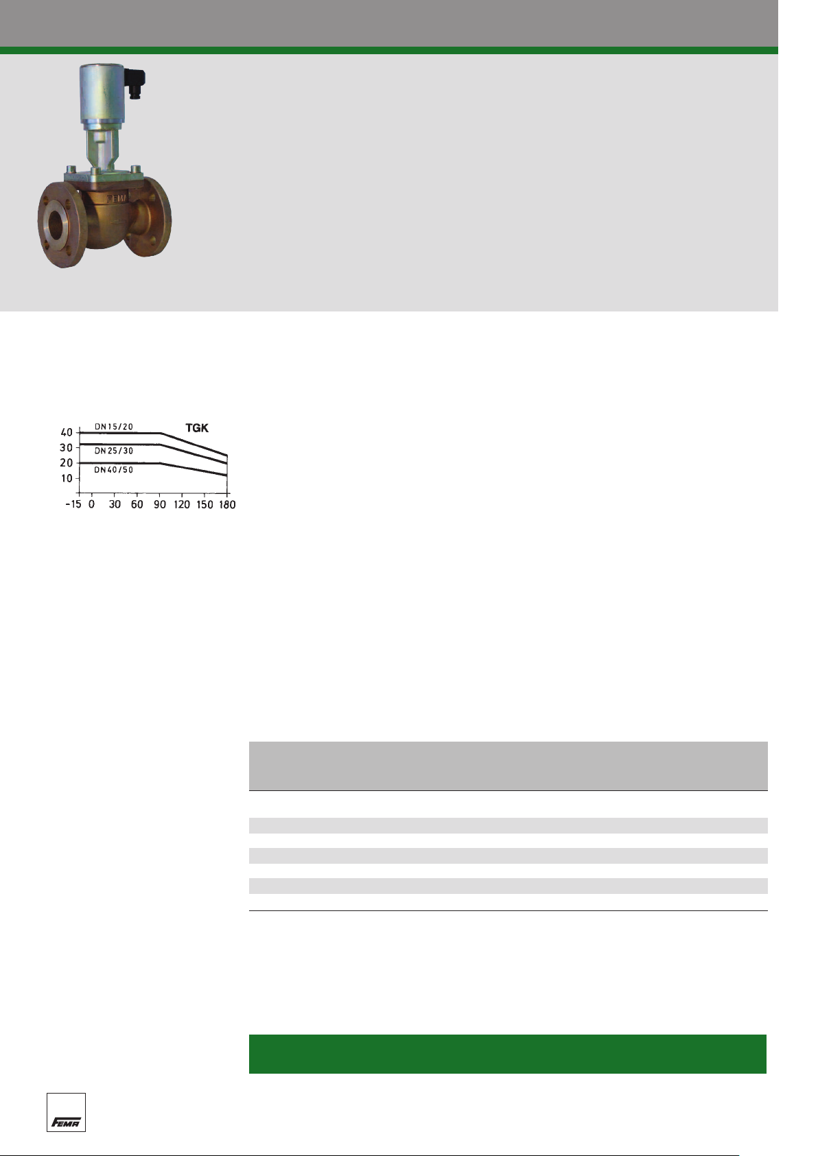
TGK series
For medium temperatures up to 180°C
T40G31FK
Limits of use
(applies only to the “normally closed”
operating mode)
Perm. working pressure (bar)
Medium temperature (°C)
The piston-type solenoid valves of the
T
GK series are suitable for hot water, steam,
fuel oil and other non-aggressive media up to
a temperature of 180°C.
Technical data
Type
Operating mode Normally closed (standard version) or normally open (on request)
Type of construction Piston-type solenoid valve, coupled
Materials Casing: Bronze Rg 5 to DIN 1705
Sealing materials Piston: T
Mounting position Solenoid system preferably upright. Horizontal mounting position
Outdoor installations fr = suitable for outdoor use
Ambient temperature -15°C to +60°C
Temperature of medium -15°C to +180°C
Flanges To DIN 2501 Part 1
Recommended weld-on flanges PN 40 to DIN 2635
Maintenance The valve should be operated 5-10 times per month to prevent
2/2-way
no minimum dif
Internal parts: Brass (CuZn) and corrosion-resistant steel
Nozzle: Cone seal made of stainless steel.
Static seal: EPDM.
only permitted for DN 15–DN 32. The solenoid system should not
hang downwards.
PN 40 for DN 15–32
PN 25 for DN 40/50
the piston from sticking. No further maintenance is required.
The cooling piece between the valve section
a
nd the solenoid actuator ensures good heat
discharge and protects the solenoid against
overheating.
ferential pressure required
eflon (PTFE).
Product Summary
DN kvsvalue Working Screwed Flange
3
(mm) (m
TGK series (up to 180°C)
15 4.0 G 1/2“ T15G31MK T15G31FK
20
25 10 G 1“ T25G31MK T25G31FK
32
40 34 T40G31FK
50 40 T50G31FK
All valves ar
Identified by the letter “U”. For example: T25G31FU
NB:
o avoid heat build-up, the solenoid system must not be insulated or painted.
T
/h) (bar) thread Type Type
4.8 G 3/4“ T20G31MK T20G31FK
13
e also available in nor
s
pressure Internal connection connection
G 1 1/4“ T32G31MK T32G31FK
of use)
See graph
opposite (Limits
mally open versions.
Degree of protection:
IP 65
Page 4

Solenoid valves I 11
Piston-type solenoid valves
T/K series
Solenoid actuators G 31 for standard version
Only solenoids of the G 31 series are used to
o
perate piston-type solenoid valves in nonexplosion-proof installations. All G 31 solenoid
actuators are generally equipped with a DC
coil and plug connector with contact
a
rrangement according to DIN 43 650. The
solenoid coils are fully encapsulated in silicone
Technical data
Degree of protection
Power consumption 50 VA with warm solenoid.
Nominal voltages Alter
Important: In all orders or enquiries, the supply voltage and current type (AC or DC) must be specified.
IP 65 to DIN 40 050
fr = suitable for outdoor use.
nating current (AC):
230 V, 45–60 Hz
Rectifier is built into the connection plug
ect current (DC):
Dir
24 V
Supplied without rectifier
rubber (to protect against moisture).
A
ll solenoid actuators are mutually
interchangeable.
The name of the solenoid actuator forms part
o
f the type designation of the complete solenoid
valve. For example: T 40 G 31 F
Valve with standard solenoid G 31
Electrical connection for switching device G 31
The AC power supply is connected to the terminals on the PCB inside the plug. The earth conductor
is directly connected to the plug cube (underneath the PCB).
Rectifier PCB circuit diagram
Exchanging solenoid actuators
Complete G
(undo the screw on the solenoid cover plate, remove the cover and lift out the solenoid).
It is not possible to change the coil on its own.
GS type
Device socket with built-in r
Primary 230 V, 50 Hz
Secondary approx. 220 V
31 solenoid actuators can easily be r
ectifier for G 31 solenoid.
eplaced, even under pressure
Replacement rectifier and
connection plug for standard
solenoid valves
ST 5
Connection plug with seal and fastening screw (without rectifier)
Page 5

12 I Solenoid valves
Piston-type solenoid valves
T-Ex/K-Ex series
Ex solenoid actuators
Solenoid valves of type G 35-Ex, of pressurep
roof encapsulated design for use in explosion-
endangered areas, are generally equipped with
Technical data
Nominal voltages
Ex-protection
Can be used in outdoor installations. Because of the deflagration gap specified for the
Mounting position Ex-solenoid valves must only be installed with the solenoid system
Power consumption approx. 50 VA with warm solenoid.
Duty cycle 100% ED. Other technical data are the same as for G 31 solenoid
Connection cables Heat-resistant cables must be used to connect the Ex-solenoid
Alternating current (AC):
230 V, 45–60 Hz
Rectifier is built into the solenoid casing
ect current (DC): 24 V, supplied without rectifier
Dir
Pressure-proof encapsulation ( II2 G/D EEx de IIC T4 IP 65 T 125°C).
Suitable for
solenoid, the solenoid actuator must be installed vertically.
A protective hood is needed to give the solenoid additional
protection against weather conditions.
standing vertically. Other mounting positions are not permitted.
actuators.
actuator. The solenoid temperature must not exceed 125°C.
a DC coil which is mounted in a pressure-proof
e
ncapsulated cast steel housing and sealed with
silicone rubber.
≥
≥
Zone 1, 21.
Valve with Ex-solenoid G 35-Ex
NB:
Solenoid actuators of older
G3-Ex solenoid valves cannot be
eplaced under pressure.
r
Replacing solenoid actuators on Ex-solenoid valves G
Solenoid actuators with the type designation G 35-Ex can also be replaced under pressure.
The procedure is as follows:
Removing the old solenoid
1. Turn off the power and remove the connection cable.
2. Loosen the three M6 Allen screws on the solenoid cover (aluminum hood),
(2–3 turns of the screw are sufficient).
them
3. Remove the Allen screws on the bottom mounting flange of the solenoid and carefully lift up the
whole solenoid.
Fitting a new solenoid
4. Before fitting the new solenoid, loosen the three Allen screws on the solenoid cover (aluminum hood),
but do not undo them completely (2–3 tur
5. Put the solenoid in place carefully, moving it gently to and fro to allow the solenoid cover plate lying
inside (not visible) to center itself on the guide tube. The mounting flange must lie squar
lower flange.
6. Align the solenoid head: The terminal connection box must face against the flow direction.
7. Tighten the 4 fastening screws on the lower flange.
ighten the thr
T
8.
9.
Remove the terminal connection cover and carry out electrical connections in accordance with
VDE guidelines.
10.Fit the terminal connection cover.
11.Commission the valve in accordance with the accompanying instruction manual.
ee M6 Allen scr
ews on the solenoid cover.
ns of the screw are sufficient).
35-Ex
but do not remove
ely on the
Page 6

Solenoid valves I 13
Piston-type solenoid valves
T/K series
Mounting instructions
Satisfactory operation demands expert
i
nstallation with due observance of the technical
Mounting position
A vertical mounting position (solenoid system standing upright) is preferable if at all possible.
In general, the solenoid system should not hang downwards. In the case of Ex-solenoids, only
a vertical mounting position is permissible. For information about the mounting position of valves,
refer to the individual data sheets.
Installation location
Solenoid valves contain moving parts which are subject to natural wear.
Therefore, care must be taken to ensure that valves can be dismantled for repair.
Risk of freezing
If solenoid valves ar
that such temperatures may occur, the customer must take steps to ensure that valves cannot freeze
up — due to condensation for example.
Painting the solenoid
Solenoid coils must not be painted or lacquered, as this will hinder the dissipation of heat.
Stress-free mounting
Stresses from the pipe system acting on the valve can cause the piston to stick, hindering or even
preventing it from opening and closing.
The solenoid casing must on no account be used as a lever during mounting (key faces are cast on
the valve body for this purpose).
e operated at ambient or medium temperatures of 0°C or lower, or if it is possible
regulations applicable to the planning and
c
onstruction of the installation as a whole.
Maintenance
The valve should be operated 5-10 times per month to prevent the piston from sticking. No further
maintenance is r
Back-pressure
If the back-pressure (at the output of the valve) is 0.2 bar higher than the pressure on the input side,
the piston or diaphragm is automatically lifted fr
through the solenoid valve.
Commissioning
Upon first commissioning, medium should be admitted to the valve very gently so as to allow any air
trapped in the valve to escape. Sudden admission at working pressure on first commissioning may
cause uncontr
Dirt trap
The operation of
valve. Welding beads, rust flakes, scale and other impurities may prevent a tight seal on the valve
seat. Ther
This will greatly improve the reliability of the installation.
Factory certificates and acceptance testing certificates
y cer
Factor
supplied for all piston-type valves if r
The factory certificate contains information about the quality of the materials used and confirms that
the solenoid valve was subjected to rigorous pressure tests, leak tests and function tests prior to
delivery. The costs of the certificates are shown in the relevant price list.
equired.
om the seat. In this case the medium may flow back
olled opening of the valve.
solenoid valves is often impaired by impurities in the medium flowing through the
e it is advisable to install a dirt trap before every solenoid valve.
efor
tificates in accor
dance with EN 10
equired, and enclosed with the delivery documents.
204 and DIN 50 049, section 2.3 or 3.1 B, can be
Spare parts
For spare parts such as solenoids and connection plugs, refer to the relevant price list.
Page 7

14 I Solenoid valves
Piston-type solenoid valves
Faults and troubleshooting
If the valve does not function correctly, carry out the following checks:
1. Is the flow direction correct? Observe the arrow on the valve.
2. Is the power supply properly connected?
3
. Is the operating voltage present?
4. Does the operating voltage correspond to the details on the rating plate?
5. Is the rectifier in working order?
6. Is the solenoid coil in working order?
T
he condition of solenoid coils and rectifiers can easily be checked by carrying out resistance, current
and voltage measurements.
If the coils and rectifiers are satisfactory, solenoid actuators of the G 31 and G 35 series should give
the following readings:
Mains voltage Coil Coil current
230 V~ / = 990–1050 224 mA
24 V = 11.35–12.02 2.1 A
resistance consumption
Ohms approx.
All values are measured on the DC side, i.e. after the rectifier, and are for a solenoid temperature
20°C.
of
The values are approximate. If the measured values deviate significantly from those shown in the table,
either the solenoid coil is faulty (broken or shorted coil) or the rectifier is damaged.
If a valve actuator with a DC coil is accidentally charged with alternating current at the same level, it
will not be damaged but the valve will not operate. Voltage measurements on the secondary side of
the rectifier without load (coil) are not meaningful, therefore you should never measure the DC voltage
with the system unplugged.
Replacing rectifiers on Ex-solenoid valves
Rectifiers on Ex-solenoid valves must only be replaced by an authorised electrician. The greatest care
must be taken, with due observance of safety regulations.
The following procedure must be observed:
1. Turn off the power and remove the terminal box cover.
2. Disconnect and remove the connection cable.
Undo the M6 Allen scr
3.
NB: Remove the terminal housing carefully to avoid tearing the coil connection wires.
4. Remove the clip (to do this you have to undo the two M3 screws).
5. Pull off the connection wire to the coil. NB: Use thin-nosed pliers and grip it by the plug; do not pull
it by the connection cable (otherwise the coil wire may be torn off).
6. Detach the connecting wire on the primary side of the rectifier at the cable guides (use open-ended
spanner SW
7. Remove the rectifier (black plastic housing) including the white flat connector guide.
8. Install the new rectifier in the reverse order. Make sure the connection plug of the coil wire is fully
inser
connector guide.
When fitting the ter
cables do not get caught.
7).
ted in the flat connector guide. The ends of the connector must not project beyond the flat
ews and remove the terminal connection housing.
minal connection housing on the solenoid housing, make sur
e the connection
Page 8

Series
TG, K, LG
Solenoid valves I 15
Piston-type solenoid valves
T/K series
Dimensioned drawings/weights
Quantity
DN Screwed version Weight Flange version Weight
G M SW kg F B D d LK b L i kg H h
15 G 1/2 82 32 4.5 150 20 95 45 65 18 14 4 6.1 137.8 35
20 G 3/4 82 32 4.5 150 20 105 58 75 18 14 4 6.6 137.8 35
85 20 14 4 9.0 158.3 47.5
25 G 1 112 50 5.8 180 31 115
32 G 1 1/4 112 50 5.8 180 31 140 78 100 20 18 4 10.5 158.3 47.5
40 200 45 150 88 110 20 18 4 15.0 181.8 53
50 230 45 165 102 125 22 18 4 17.5 181.8 53
Series
TG-Ex, K-Ex, LG-Ex
68
Grounding
Quantity
DN Screwed version Weight Flange version Weight
G M SW kg F B D d LK b L i kg H h
15 G 1/2 82 32 5.8 150 20 95 45 65 18 14 4 7.6 197.9 35
20
25 G 1 112 50 8.0 180 31 115 68 85 20 14 4 11.0 235.4 47.5
32 G 1 1/4 112 50 8.0 180 31 140 78 100 20 18 4 12.5 235.4 47.5
40 200 45 150 88 110 20 18 4 16.5 253.9 53
50
G 3/4 82 32 5.8 150 20 105 58 75 18 14 4 8.0 197.9 35
165 102 125 22 18 4 20.0 253.9 53
45
230
Page 9

16 I Solenoid valves
Piston-type solenoid valves
T/K series
Dimensioned drawings/weights
Series
TGK, LGK
Quantity
DN
15 G 1/2 82 32 5.6 150 20 95 45 65 18 14 4 7.5 238.3 35
20 G 3/4 82 32 5.6 150 20 105 58 75 18 14 4 7.8 238.3 35
25
32 G 1 1/4 112 50 7.2 180 31 140 78 100 20 18 4 12.0 256.8 47.5
40 200 45 150 88 110 20 18 4 16.0 277.3 53
50 230 45 165 102 125 22 18 4 19.0 277.3 53
Screwed version Weight Flange version Weight
G M SW kg F B D d LK b L i kg H h
1 112 50 7.2 180 31 115 68 85 20 14 4 10.5 256.8 47.5
G
 Loading...