

Honeywell Tema-Voyager Compact Installation Manual
May 2014 © 2014 Honeywell. All rights reserved. 800-07074, Rel. 2.0b
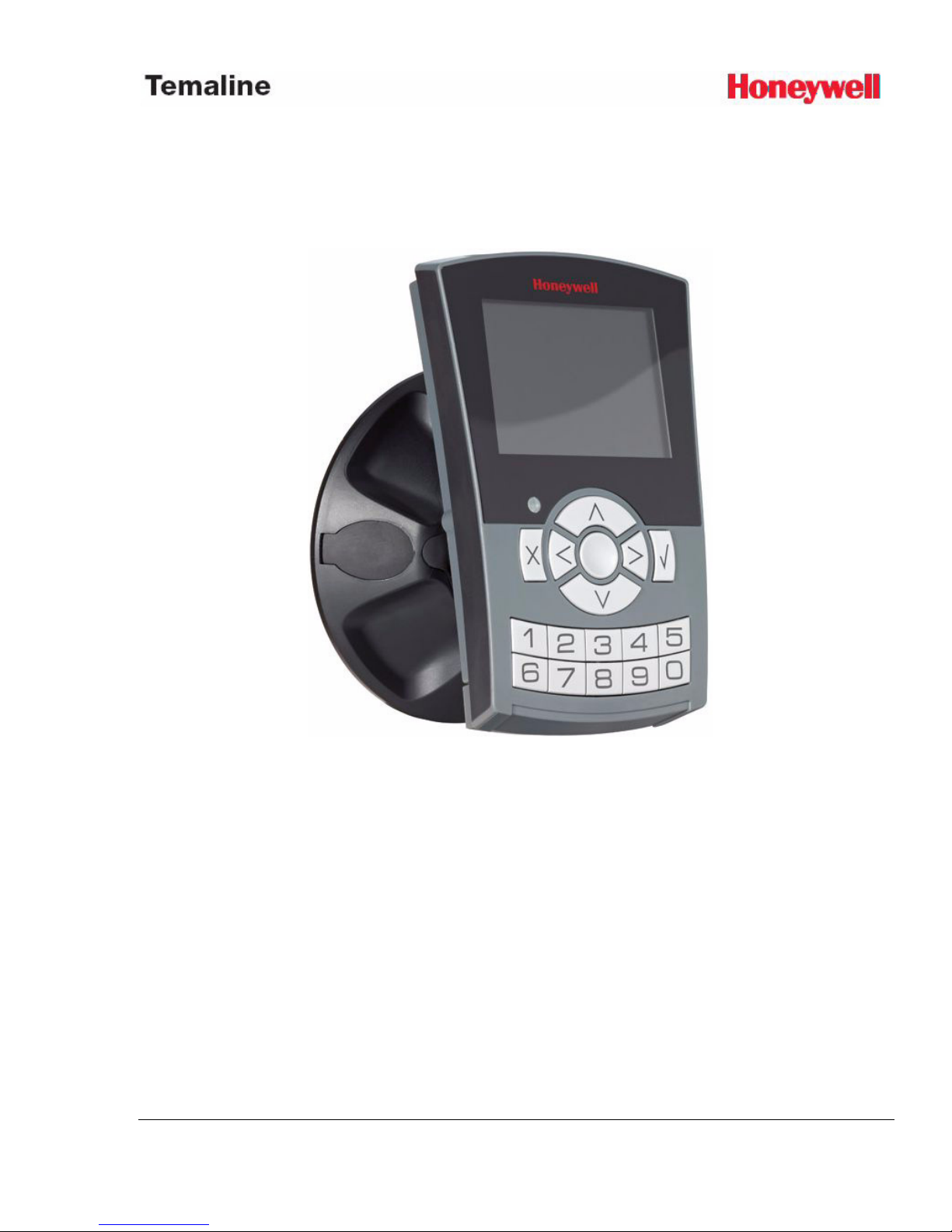
Tema-Voyager™ Compact
Installation Guide

ii https://extranet.honeywell.com
Notice
This document contains Honeywell proprietary information. Information
contained herein is to be used solely for the purpose submitted, and no part of this
document or its contents shall be reproduced, published, or disclosed to a third
party without the express permission of Honeywell Europe.
This document and the data in it shall not be duplicated, used or disclosed to
others for procurement or manufacturing, except as authorized by and with the
written permission of Temaline, Inc.The information contained in this document
or in the product itself is the exclusive property and trade secrets of Temaline, Inc.
Copyright laws of the United States protect all information in this document or in
the software product itself.
While this information is presented in good faith and believed to be accurate,
Honeywell disclaims the implied warranties of merchantability and fitness for a
purpose and makes no express warranties except as may be stated in its written
agreement with and for its customer.
In no event is Honeywell liable to anyone for any direct, special, or consequential
damages. The information and specifications in this document are subject to
change without notice.
Copyright 2014 – Honeywell International Inc.
Trademarks
Tema-Voyager
TM
is a trademark of Honeywell International Inc.
MIFARE
®
is a registered trademark of Philips Electronics N.V.
HID, iCLASS
®
, and Sokymat are trademarks or registered trademarks of HID
Global Corporation.
Any other trademarks that appear in this document are used only to the benefit of
the trademark owner, with no intention of trademark infringement.
Compliance
To obtain applicable EU compliance Declaration of Conformities for this product,
please refer to our website, https://extranet.honeywell.com. For any additional
information regarding the compliance of this product to any EU-specific
requirements, please send email to temaline.orders@honeywell.com
Document Release Issue Date
800-07074 2.0

iii
Support and other contacts
For technical assistance, call your nearest Honeywell office.
iv https://extranet.honeywell.com

v
Contents
Warnings and Cautions ........................................................................................1
Before installation .................................................................................. 1
Fire Safety and Liability Notice .............................................................1
Damage during shipment .....................................................................1
Electrostatic discharge .........................................................................1
Disclaimer – Product Liability; Mutual Indemnification ................... 2
Compliance .......................................................................................... 2
Unpacking...............................................................................................................3
Shipping instructions ...........................................................................................4
Limited warranty ...................................................................................................5
Confidentiality ........................................................................................................6
Device overview ....................................................................................................7
Preparing for installation.......................................................................................8
Contents of the kit ..................................................................................8
Readers .................................................................................................8
Supports ...............................................................................................8
Toolkit for reader .................................................................................8
Toolkits for supports............................................................................ 9
Mounting tools .....................................................................................10
Wire characteristics ..............................................................................10
Power supply wire .............................................................................10
Ethernet connector and cable .............................................................11
Input/output/RS485 wire ....................................................................11
Mounting the device ............................................................................................13
Device connectors ................................................................................13
Mounting the reader on the support ......................................................14
Mounting the reader on the wall mount .............................................14
Mounting the reader on the swivel support .......................................21

CONTENTS
vi https://extranet.honeywell.com
Turnstile mounting using the swivel support .................................... 34
Setting inputs, outputs, and jumpers ................................................................35
Digital inputs ....................................................................................... 35
Supervised inputs ................................................................................ 36
Outputs ................................................................................................ 37
External relays powered by the reader .............................................. 37
Connecting the door lock directly using an external power supply .. 38
Jumpers ................................................................................................ 39
Voyager door backup line...................................................................................40
Voyager door module..........................................................................................42
Technical specifications .....................................................................................44
Regulation ............................................................................................................47
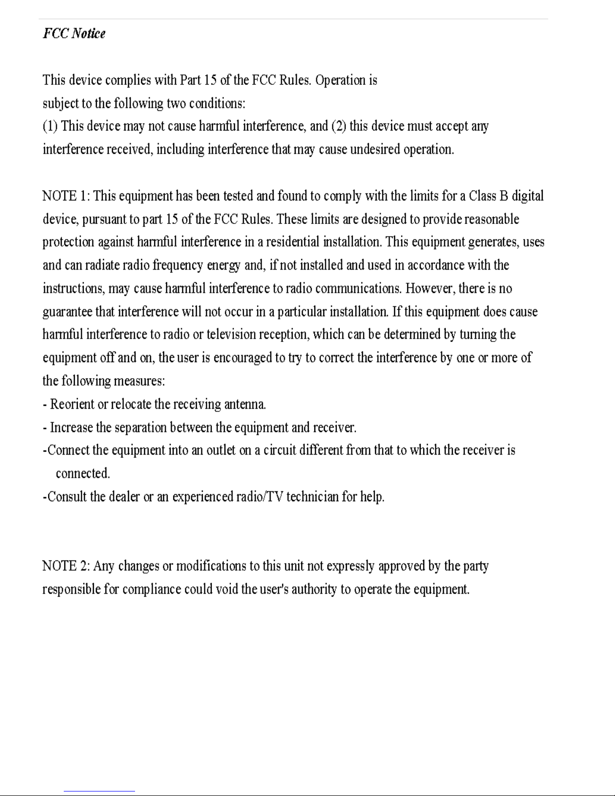
FCC Notice ......................................................................................... 47
Industry Canadian Compliance Statement .......................................... 48
Australian CTick Conformity .............................................................. 48
Appendix 1- Internal Jumpers ............................................................................49
Recycling.............................................................................................................. 51
1
Warnings and Cautions
Before installation
Warning: Before installation, TURN OFF the external circuit breaker
which supplies power to the device.
Before connecting the device to the power supply, verify that the output
voltage is within specifications of the power supply. (See “Technical
specifications” on page 44.)
Do not apply power to the device until after the installation has been
completed. The equipment can be damaged if this precaution is not
observed.
Fire Safety and Liability Notice
Warning: Never connect card readers to any critical entry, exit door, barrier,
elevator or gate without providing an alternative exit in accordance with
all the fire and life safety codes pertinent to the installation.
These fire and safety codes vary from city to city and you must get
approval from local fire officials whenever using an electronic product to
control a door or other barrier. Use of egress buttons, for example, may be
illegal in some cities. In most applications, single action exit without prior
knowledge of what to do is a life safety requirement. Always make certain
that any required approvals are obtained in writing. DO NOT ACCEPT
VERBAL APPROVALS SINCE THEY ARE NOT VALID.
Damage during shipment
Caution: IF ANY DAMAGE TO THE SHIPMENT IS NOTICED, A
CLAIM MUST BE FILED WITH THE COMMERCIAL CARRIER
RESPONSIBLE FOR THE DAMAGE.
Electrostatic discharge
Caution: Electrostatic discharge (ESD) can damage integrated circuits and
modules.
To prevent damage always follow these procedures:

2 https://extranet.honeywell.com
• Use static shield packaging and containers to transport all
electronic components, including completed reader assemblies.
• Handle all ESD sensitive components at an approved staticcontrolled workstation. These workstations consist of a desk mat,
floor mat and an ESD wrist strap. Workstations are available from
various vendors.
Note: This equipment has been tested and found to comply with the limits
for a Class B digital device, pursuant to part 15 of the FCC Rules. These
limits are designed to provide reasonable protection against harmful
interference when the equipment is operated in a commercial
environment.This equipment generates, uses, and can radiate radio
frequency energy and, if not installed and used in accordance with the
installation and user guides, may cause harmful interference to radio
communications. Operation of this equipment in a residential area is likely
to cause harmful interference in which case the user will be required to
correct the interference at his own expense.
Disclaimer – Product Liability; Mutual
Indemnification
If a Customer receives a claim that a Product or any component thereof
has caused personal injury or damage to the property of others, Customer
shall immediately notify Honeywell S.r.l. Italy in writing of all such
claims. Honeywell S.r.l. Italy shall defend or settle such claims and shall
indemnify and hold Customer harmless for any costs or damages
including reasonable attorneys’ fees which Customer may be required to
pay as a result of the defective Product or the negligence of Honeywell
S.r.l. Italy, its agents, or its employees.
Customer shall hold harmless and indemnify Honeywell S.r.l. Italy from
and against all claims, demands, losses and liability arising out of damage
to property or injury to persons occasioned by or in connection with the
acts or omissions of Customer and its agents and employees, and from and
against all claims, demands, losses and liability for costs of fees, including
reasonable attorneys’ fees, in connection therewith.
Compliance
For any additional information regarding the compliance of this product to
any EU-specific requirements, please send an e-mail to
temaline.orders@honeywell.com.

3
Unpacking
Caution: If any damage to the shipment is noticed before unpacking, a
claim must be filed with the commercial carrier.
All containers should be opened and unpacked carefully in order to
prevent damage to the contents.
Follow these steps to unpack equipment in preparation for installation:
1. Open the container and remove the unit(s) and all packing
material. Retain the container and all the packing materials. They
may be used again for reshipment of the equipment, if needed.
2. Inspect the contents to see if anything is missing. If you notice any
missing items, send an e-mail to temaline.orders@honeywell.com.
3. Visually check the contents. If you see any damage, do the
following:
a. If shipping has caused damage to the unit, file a claim with
the commercial carrier.
b. If any other defect is apparent, call for a return
authorization.

4 https://extranet.honeywell.com
Shipping instructions
To ship equipment back to Temaline, contact the customer service
department at temaline.orders@honeywell.com before returning the
equipment. When you call, please have available:
• A description of the problem or the reason you are returning the
equipment.
• Your original purchase order number, invoice number and if the
unit is still under warranty.
• A new purchase order number if the unit is not under warranty.
From the customer service department, obtain the Return Merchandise
Authorization (RMA).
Show the RMA number on all packages shipped. Packages which are not
marked with an RMA number will be refused at the factory and returned
to you COD.
Carefully pack the equipment for shipment. Use the original packing
material whenever possible

5
Limited warranty
All warranty work shall be handled through Customer who shall notify
Temaline and apply for a Return Merchandise Authorization (RMA)
number prior to returning any Product for service, repair, credit or
exchange. Temaline warrants that its Products shall be free from defects in
materials and workmanship for a period of 18 months from the date of
shipment from the Temaline warehouse. Satisfaction of this warranty shall
be limited to repair or replacement of Products which are defective or
defective under normal use. Temaline’s warranty shall not extend to any
Product which, upon examination, is determined to be defective as a result
of misuse, improper storage, incorrect installation, operation or
maintenance, alteration, modification, accident or unusual deterioration of
the Product due to physical environments in excess of the limits set forth
in Product manuals. THERE ARE NO WARRANTIES WHICH
EXTEND BEYOND THIS PROVISION. THIS WARRANTY IS IN
LIEU OF ALL OTHER WARRANTIES WHETHER EXPRESS,
IMPLIED OR STATUTORY, INCLUDING IMPLIED WARRANTIES
OF MERCHANTABILITY OR FITNESS FOR ANY PARTICULAR
PURPOSE. NO REPRESENTATION OR WARRANTY OF THE
DISTRIBUTOR SHALL EXTEND THE LIABILITY OR
RESPONSIBILITY OF THE MANUFACTURER BEYOND THE
TERMS OF THIS PROVISION. IN NO EVENT SHALL TEMALINE
BE LIABLE FOR ANY RE-PROCUREMENT COSTS, LOSS OF
PROFITS, LOSS OF USE, INCIDENTAL, CONSEQUENTIAL OR
SPECIAL DAMAGES TO ANY PERSON RESULTING FROM THE
USE OF TEMALINE’S PRODUCTS.

6 https://extranet.honeywell.com
Confidentiality
All software, drawings, diagrams, specifications, catalogs, literature,
manuals and other materials furnished by Honeywell HSG -Temaline
relating to the design, use and service of the Products shall remain
confidential and shall constitute the proprietary rights of Honeywell HSG
-Temaline and Customer agrees to treat such information as confidential.
Customer shall acquire no rights in the design of the Products or the
related materials except to use such information solely for the purpose of
and only during the time it sells the Products. Customer shall not copy the
design of any of the Products or use or cause to be used any Product
design or related materials for its own benefit or for the benefit of any
other party. The covenants contained in this section shall remain effective
throughout the term of this Agreement and thereafter unless specifically
waived by Honeywell HSG -Temaline in writing.

7
Device overview
The Voyager Compact is an RFID proximity smart technology card reader
that is used with access controls and time and attendance systems.
These installation instructions contain the following information:
• Mounting instructions
• Connecting the reader to the network and door
Temaline recommends that before you begin, read and familiarize yourself
with these instructions. This preparation should facilitate the installation.

8 https://extranet.honeywell.com
Preparing for installation
Contents of the kit
Before you begin, unpack the shipment and check the parts list against the
components in the shipment.
Your shipment should contain one reader, one support, one toolkit for the
reader, and one toolkit for the support.
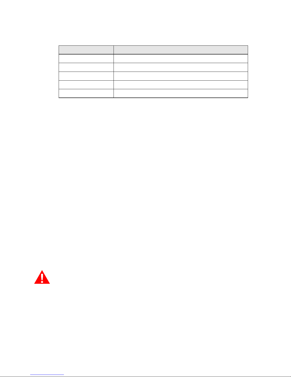
Readers
Your kit should include one of the following readers:
Supports
Your kit should include one of the following supports:
Toolkit for reader
Your kit should include a toolkit for the reader that contains the following
items:
Label Name Description
VCU-01xxxxxxxxxx Voyager Compact Unit HID Prox
VCU-02xxxxxxxxxx Voyager Compact Unit MIFARE
VCU-03xxxxxxxxxx Voyager Compact Unit HID Prox & MIFARE
VCU-04xxxxxxxxxx Voyager Compact Unit iClass
VCU-05xxxxxxxxxx Voyager Compact Unit iClass & HID Prox
VCU-06xxxxxxxxxx Voyager Compact Unit Sokymat Prox
VCU-07xxxxxxxxxx Voyager Compact Unit Sokymat Prox & MIFARE
Label Name Description
VCM-W7015 Wall Base Support
VCM-T7015 Turnstile Base Support
VCM-S7015 Swivel Base Support
Quantity Description
1 Green connector 1x5 position (3.5 mm)
1 Green connector 1x6 position (3.5 mm)

9
Toolkits for supports
Your kit should contain one of the following three support toolkits:
• Wall support toolkit
• Turnstile support toolkit
• Swivel support toolkit
The wall support toolkit contains the following items:
The turnstile support toolkit contains the following items:
1 Balance resistors kit and diodes
1 RS-485 connector with cable
1 Jumper
Quantity Description
Quantity Description
1 Tamper switch with cable
1 Drilling template
4 Screws for Fisher plug S5V
4 Plastic plug Fisher S5C
2 Torx screws for reader closing
Quantity Description
1 Tamper switch with cable
1 Drilling template
4 Screws for turnstile
2 Torx screws for reader closing
10 https://extranet.honeywell.com
The swivel support toolkit contains the following items:
Mounting tools
The following screwdrivers are required for the installation:
• One small cross screwdriver
• One T10 Torx screwdriver
• One medium cross screwdriver
• One 0-1 flat head screwdriver
Wire characteristics
To optimize the installation, Temaline recommends that you use the cable
with smallest AWG allowed according to the tables below. If the power
supply wire exceeds the AWG 20, Temaline strongly recommends that
you terminate the wire with a smaller AWG.
Power supply wire
The Voyager device can be powered either with a 10V-30V DC
power supply or 48V PoE. To determine the correct size of the power
cable, see the table below.
Warning: Max voltage cable drop allowed must not exceed 0.8 VDC when
the voltage is 12V. (Typical input current is 500mA.)
The tables below show the values for one reader. If more than one reader
is connected to the same line, divide the distance by the number of the
readers on the same line.
The following table lists examples of wire gauge and distance for a 12V
and a 24V power supply.
Quantity Description
1 Tamper switch with cable
1 Drilling template
3 Screws for Fisher plug S5V
3 Plastic plug Fisher S5C
2 Torx screws for reader closing

11
Ethernet connector and cable
For the Ethernet connector and cable, Temaline recommends:
•
RJ45 male connector: Module plug assembly, 8 position, unshielded,
round cable, stranded wire, high performance.
•
Cable: APC CAT 5 UTP 4 PAIR, 24 AWG, no longer than 100 ft.
Input/output/RS485 wire
Input wires: Use a twisted pair cable for the contacts connections. AWG24
or AWG26 is recommended for the best wire recovery behind the reader.
The following table lists wire gauges and distances for inputs contacts.
Max distance (m) from the
Power Supply for 12V
Max distance (m) from the
Power Supply for 24V
AWG mm2 Ohm/km
30 190 20 0.52 34
20 125 22 0.35 52
12 75 24 0.2 85
8 45 26 0.13 137
AWG mm2 Ohm/km Max distance (m)*
22 0.35 52 240
24 0.2 85 147
26 0.13 137 93

12 https://extranet.honeywell.com
• Output wires: AWG24 or AWG 26 are recommended when the load is
powered with current @30mA. This will facilitate the reader closing.
Use the minimum AWG allowed from the table below when the power
is provided by an external power supply and the current is more than
30mA.
*One-volt voltage drop is considered typical.
•
RS-485 wire: Cable spec: UL, 24 AWG, 85ohm/Km twisted. Because
the RS-485 is used for door backup line between the two readers
installed on the two sides of the door. Also, the RS-485 is used for
connection of a Voyager device with a Voyager door module installed
on the safe side of the door, where the cable is usually short.
AWG mm2 Ohm/km Max distance (m)*
20 0.52 34 550
22 0.35 52 380
24 0.2 85 200
26 0.13 137 130
AWG mm2 Ohm/km Max distance (m)*
20 0.52 34 15
22 0.35 52 10
24 0.2 85 5.5
26 0.13 137 3.5
 Loading...