

Honeywell TemaKey Installation Manual
TABLE OF CONTENTS Page 3
Modular terminal
Installation Manual

Page 4 Installation Manual
TABLE OF CONTENTS
Installation Manual........................................................................................ 3
FCC NOTICE................................................................................................. 6
Canadian Compliance Statement ......................................................... 6
PRELIMINARY OPERATIONS .......................... 7
Mounting Instructions ................................................................................... 7
Arranging the Cable Tubes and Junction Boxes ......................................... 8
Cabling: Recommendations ................................................................. 8
Electrical Connections................................................................................ 10
LONWORKS Data Cables......................................................................... 11
Mounting the Unit on the Wall .................................................................... 13
Horizontal Assembly – Single Module ................................................ 13
Horizontal Assembly – Triple Module ................................................. 14
Combined Assembly - Single and Triple Modules ............................. 15
Fastening the Cables .......................................................................... 17
Vertical Assembly ................................................................................ 18
Channeling the Cables from the Bottom of the Box ........................... 19
INSTALLATION ........................................... 20
Combining the Modules ............................................................................. 20
Reader ................................................................................................. 20
Keyboards ........................................................................................... 20
Display................................................................................................. 20
Terminals ............................................................................................. 21
Terminals with Keyboards................................................................... 21
Interactive Terminals ........................................................................... 22
Interactive Terminals with Keyboards ................................................. 22
Attaching the Modules to the Wall.............................................................. 23
Applying the Entry/Exit Labels.................................................................... 24
Identification via Bar Code.......................................................................... 25
Summary of Modular Devices .................................................................... 26
RTU-B07 (Proxy Reader for HID Cards)............................................................ 27
RTU-B12 (Proxy Reader for MIFARE Cards)...................................................... 28
RTU-C01 (Alphanumeric LCD Module)............................................................. 29
RTU-C02 (Graphic LCD Module) ..................................................................... 30

Installation Manual Page 5
RTU-T01 (Numeric Keyboard Module) ............................................................. 31
Optional Parts ............................................................................................. 32

Page 6 FCC NOTICE
FCC NOTICE
NOTE: This equipment has been tested and found to comply with the limits
for a Class B digital device, pursuant to Part 15 of FCC Rules. These limits
are designed to provide reasonable protection against harmful interference
in a residential installation. This equipment generates, uses and can radiate
radio frequency energy and, if not installed and used in accordance with the
instructions, may cause harmful interference to radio communications.
However, these is no guarantee that interference will not occur in a particular
installation.
If this equipment does cause harmful interference to radio or television
reception, which can be determined by tuning the equipment off and on, the
user is encouraged to try to correct the interference by one or more the
following measures:
-- Reorient or relocate the receiving antenna.
-- Increase the separation between the equipment and receiver.
-- Connect the equipment into an outlet on a circuit different from that to
which the receiver is connected.
-- Consult the dealer or an experienced radio/TV technician for help.
Caution: any modification or change not expressely approved by the party
responsible for compliance could void the user’s authority to operate the
equipment.
Canadian Compliance Statement
This Class B Digital apparatus meets all the requirements of the Canadian
Interference-Causing Equipment Regulations.
Cet appareil numerique de la classe B respecte les exigences du Reglement
sur le material broilleur du Canada.
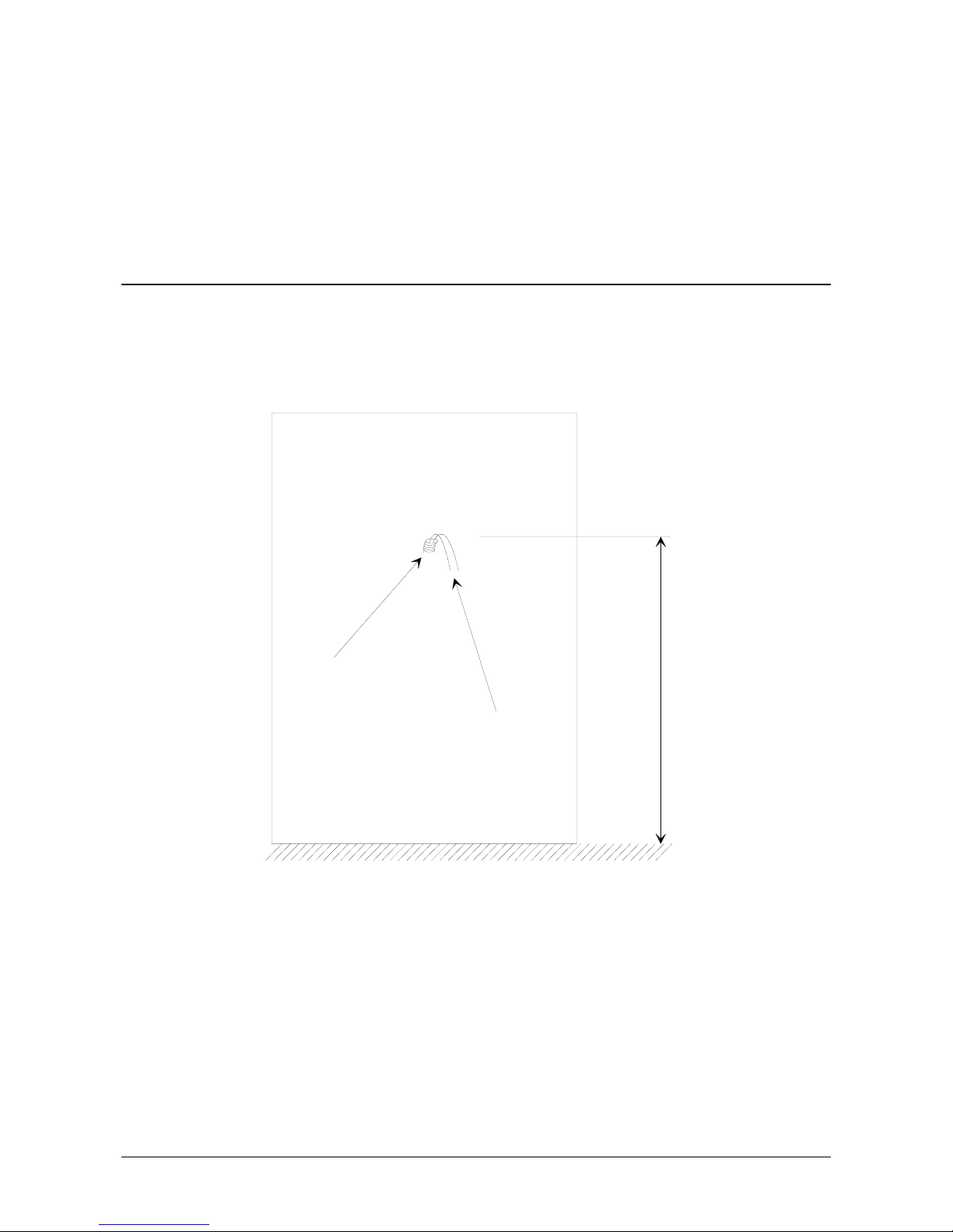
Mounting Instructions Page 7
PRELIMINARY OPERATIONS
Mounting Instructions
The cables are attached to an encased box. Make sure that you place the
box at a height of 120cm from the floor (see Figure 1).
tube
cables
1
2
0
c
m
floor
Figure 1: Space requirements for mounting
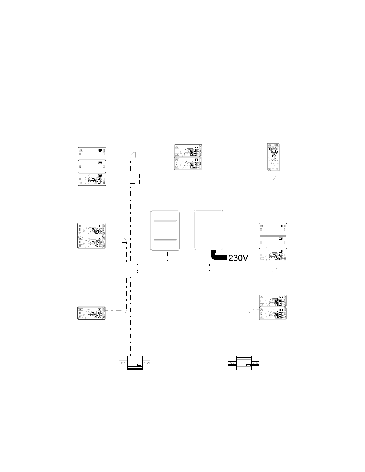
Page 8 Arranging the Cable Tubes and Junction Boxes
Arranging the Cable Tubes and Junction
Boxes
All the cables consist of 4 wires that must be connected in parallel from one
node to the next. It is possible to link nodes in free topology, i.e. by means of
a star or bus configuration.
Cabling: Recommendations
Figure 2 provides an example of a typical free topology installation.
T
em
aS
e
rver
TemaPower
Figure 2: Example of a free topology installation
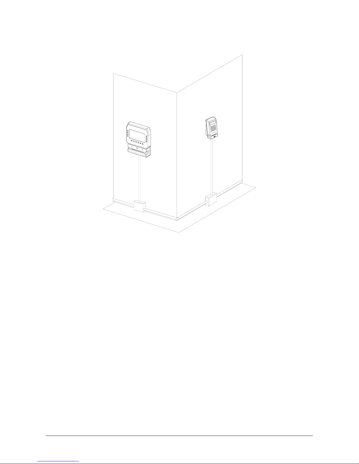
Arranging the Cable Tubes and Junction Boxes Page 9
If you want to mount the tubes on the surface of the walls, it is advisable to
place the junction boxes under each terminal (see example in Figure 3).
Figure 3: Location of the junction boxes
Page 10 Electrical Connections
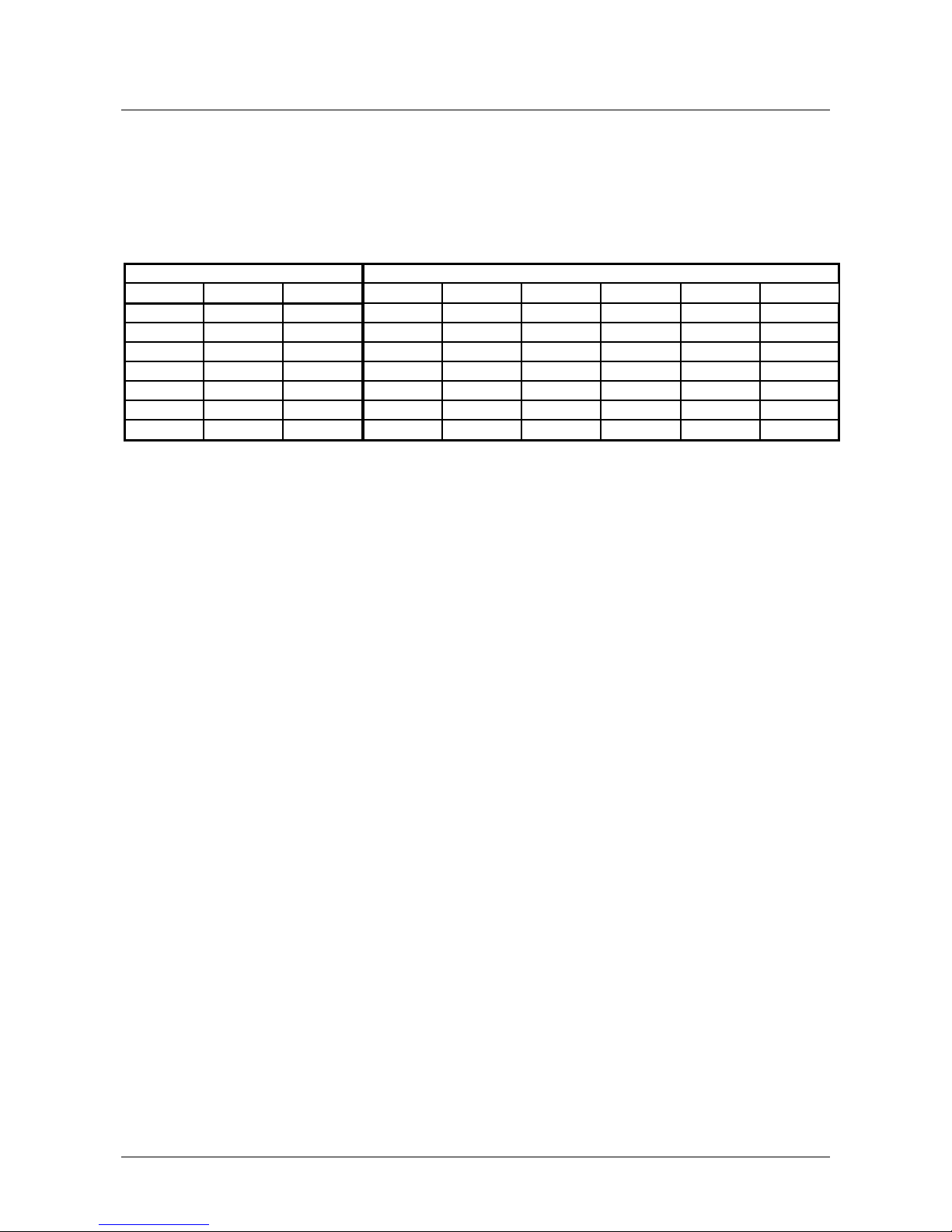
Electrical Connections
The RTU is powered at low voltage (12VDC 120mA) by a battery-operated
power supply module (RTU-Qxx). When determining the correct size for
power cables, refer to the table below.
Type of cable Lengt h (m) in relat ion t o effect ive load
A
WG mm2 ohm/Km 100 [mA] 200 [mA] 50 0 [mA] 1 [A] 2 [A] 5 [A]
12 3,3 5,7 1754 877 351 175 88 35
14 2 8,8 1136 568 227 114 57 23
16 1,3 14 714 357 143 71 36 14
18 0,9 21 476 238 95 48 24 10
20 0,6 34 294 147 59 29 15 6
22 0,35 52 192 96 38 19 10 4
24 0,2 85 118 59 24 12 6 2
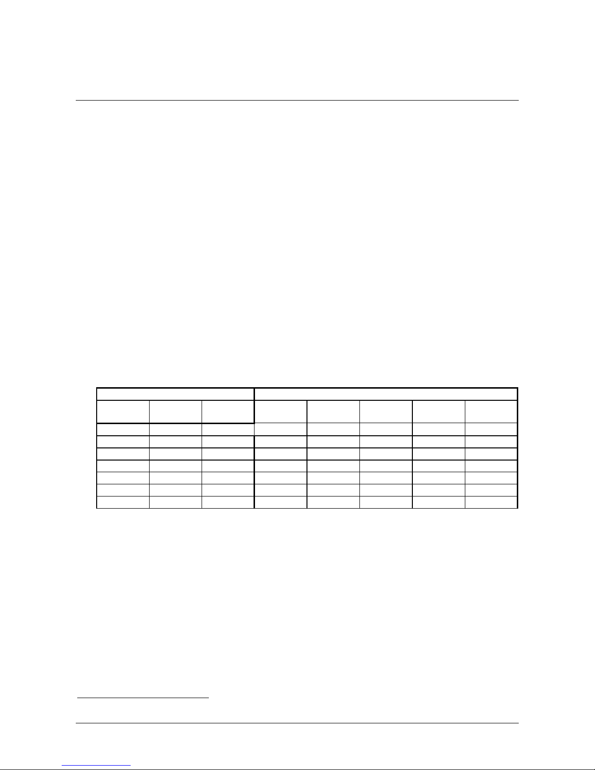
LONWORKS( Data Cables Page 11
LONWORKS Data Cables
• The LONWORKS
1
data cable must be twisted pair
• In a free topology configuration, the sum total of the sections must not
exceed 500m
• In a bus configuration, the sum total of the sections must not exceed
2700m
• In a free topology configuration, activate the 50ohm terminator by placing
the appropriate jumper on the FTT10A plug-in of the CTU-PLG06 board
inside the TemaServer
• In a bus configuration, place two terminators (with resistance values of
100ohm 1% ½W) at each end of the bus
• Check that the length of the L
ONWORKS
data cable corresponds to the
norms indicated in Table 1.
Type of cable Length [m] in relation to cable capacity
AWG mm2 Ohm/Km 50nF/Km 100nF/Km 200nF/Km 500nF/Km 1uF/Km
12 3,3 5,7 2676 1892 1338 846 598
14 2 8,8 2153 1523 1077 681 482
16 1,3 14 1707 1207 854 540 382
18 0,9 21 1394 986 697 441 312
20 0,6 34 1096 775 548 346 245
22 0,35 52 886 626 443 280 198
24 0,2 85 693 490 346 219 155
Table 1: Length/capacity of LONWORKS data cables (m)
1
LONWORKS® is a trademark of Echelon Corporation
 Loading...