

Honeywell TB7300A5x14B, TB7305A5x14B, TB7300C5x14B, TB7305C5x14B, TB7350C5x14B Integration Manual
...
Put Bar Code Here
63-4524—02
BACnet Integration Manual for
TB7200 Series
Thermostat
TB7300 Series
Thermostat with
Occupancy Sensor
TB7200 & TB7300 Series
Thermostats
INTEGRATION MANUAL
More information
The additional following documentation is available on
http://customer.honeywell.com.
• TB7200 Series Installation Instructions (form number 62-
2019).
• TB7300 Series Installation Instructions (form number 62-
2018).
• PIR Application Guide for TB7200 and TB7300 Series
Thermostats (form number 63-4526).
PRODUCT OVERVIEW
The TB7200 Series PI thermostats are designed for zoning
applications, and the TB7300 Series PI thermostats are
designed for fan coil control. Both Series are communicating
thermostats with models available in BACnet
®
ZigBee
integrated into a WEBs-AX building automation system based
on the NiagaraAX
TB7200 and TB7300 Series thermostats are compatible with
the Honeywell Occupancy Sensor Cover. Thermostats
equipped with an occupancy sensor cover provide advanced
active occupancy logic, which will automatically switch
occupancy levels from Occupied to Stand-By and Unoccupied
as required by local activity being present or not. This
advanced occupancy functionality provides advantageous
energy savings during occupied hours without sacrificing
occupant comfort. All thermostats can be ordered with or
without a factory installed PIR cover.
wireless mesh protocols and can be easily
®
platform.
®
MS/TP and
Contents
Product Overview .............................................................1
Compatibility .....................................................................2
Tips and Things You Need To Know .................................2
Wiring Guidelines .............................................................3
Network Configuration ......................................................5
Network Adapter ...............................................................8
Integration ........................................................................9
Troubleshooting ................................................................14
Appendix ..........................................................................15
BACnet Objects Supported ..............................................16

BACNET INTEGRATION MANUAL FOR TB7200 & TB7300 SERIES THERMOSTATS
COMPATIBILITY
Honeywell TB7200 and TB7300 Series thermostat compatiblity information is provided in Table 1.
Table 1. TB7200 Series and TB7300 Series Thermostat Compatibility Information
WEBs-AX Controller Thermostats Per Controller* WEBStation-AX
WEB-2xx 126 3.0 or later
WEB-6xx 126 3.0 or later
WEB-7xx 126 3.5
* 128 total devices supported. One node used by controller and one for a repeater. A repeater is required if more than 64 devices
are on a bus.
TIPS AND THINGS YOU NEED TO KNOW
• Each thermostat is delivered from the factory with the default MAC address set at 254. At this value, BACnet communication is
NOT active and the device will not participate in the token pass either. The local LED status for the communication adapter at
this point is one short flash only. To enable BACnet communication, set the local MAC address configuration property of the
thermostat to any valid value from 0 to 127.
• After the initial configuration of your device and if your BAS allows you to remove objects, we suggest that you remove all the
configuration objects to prevent unnecessary polling of non used objects and to help speed up the network.
• All configuration objects are available and accessible locally from the device itself using the local configuration routine. Please
refer to the PIR Application Guide for TB7200 and TB7300 Series Thermostats (form number 63-4526).
• In its default mode of operation, the device will automatically match its baud rate to the baud rate of the network. Automatic
baud rate detection will occur when the MS/TP communication port is initialized (on power up). If the network speed is
changed, the device will keep listening at the previously detected speed for 10 minutes before resuming auto-bauding. Repowering the devices will force immediate auto-bauding.
• Enumeration sets for System Mode MV16 depends on Sequence of Operation (MV15) value upon device discovery. If
required enumerations are not present, set MV15 to desired value and rediscover MV16 object. Available enumeration will
now reflect required configuration.
• Enumeration sets for MV16 depends on Fan Mode Sequence (MV58) value upon device discovery. If required enumerations
are not present, set MV58 to desired value and rediscover MV16 object. Available enumeration will now reflect required
configuration.
• Enumeration sets for MV26 and MV27 depend on Control Type (BV75) value and Pipe Number (MV52) value upon device
discovery. If required enumeration is not present, set BV75 and MV52 to desired value and rediscover MV26 and BV27 object.
Available enumeration will now reflect required configuration.
• If the device should go off-line, the following binded thermostat parameters will be released:
• Room Temperature
• Outdoor Temperature
• Occupancy
• The BACnet Data Link layer has two key parameters: the device object name and the device object ID. The device object
name must be unique from any other BACnet device object name on the BACnet network (i.e. not just the MS/TP subnetwork). The device object ID must be unique from any other BACnet device object ID on the entire BACnet network (i.e. not
just the MS/TP sub-network).
63-4524—02 2

BACNET INTEGRATION MANUAL FOR TB7200 & TB7300 SERIES THERMOSTATS
• To assign a Room Temperature (AV7) value manually, users must first enable the Override mode in the Room Temp Override
(BV8) object.
• To assign a Room Humidity (AV10) value manually, users must first enable the Override mode in the Room Humidity Override
(BV11) object.
• Device Name and Device ID properties are writable in Honeywell device object. Both properties can be renamed from any
BACnet network management tool as long as the tool itself give access to write to these properties.
WIRING GUIDELINES
Overview
Honeywell uses EIA-485 as the physical layer between their devices and supervisory controllers
For clarity we will use the term “Device” to represent any product with an active EIA-485 network connection, including Honeywell
and non-Honeywell thermostats.
Table 2. Summary of Specifications for a Honeywell EIA-485 Network
Parameter Details
Media Twisted pair 22AWG-24 AWG, shielded recommended
Characteristic Impedance 100-130 ohms
Distributed capacitance Less than 100 pF per meter (30 pF per foot)
Maximum length per segment 1200 meters (4000 feet)
Polarity Polarity sensitive
Multi-drop Daisy-chain (no T connections)
Terminations
Maximum number of nodes per segment 64 (Honeywell devices only)
Maximum number of nodes per network 128
Baud rate 9600, 19200, 38400, 76800 (Auto detect)
1. TB7200, TB7300 and/or TB7600 Series ther mostat devices
are installed at both ends of the MS/TP network:
120 Ohms resistor should be installed at each end.
2. A TB7200, TB7300 or TB7600 Series thermostat is inst alled at
one end of the MS/TP network and another device is installed
at the other end:
Install an End-Of-Line resistor value that matches the other
device’s instructions regarding the End-Of-Line resistors
3. Other devices are installed at both ends of the MS/TP
network:
Follow the other device’s instructions regarding the End-Of-Line
resistors.
3 63-4524—02

BACNET INTEGRATION MANUAL FOR TB7200 & TB7300 SERIES THERMOSTATS
Cable Type
Honeywell recommends the use of balanced 22-24 AWG twisted pair with a characteristic impedance of 100-130 ohms,
capacitance of 30 pF/ft or lower. A braided shield is also recommended.
Impedance
A value based on the inherent conductance, resistance, capacitance and inductance that represent the impedance of an infinitely
long cable. The nominal impedance of the cable should be between 100Ωand 120Ω. However using120Ω will result in a lighter
load on the network.
Capacitance (pF/ft)
The amount of equivalent capacitive load of the cable, typically listed in a per foot basis. One of the factors limiting total cable
length is the capacitive load. Systems with long lengths benefit from using low capacitance cable (i.e. 17pF/ft or lower).
63-4524—02 4
BACNET INTEGRATION MANUAL FOR TB7200 & TB7300 SERIES THERMOSTATS
M32571
DAISY CHAIN
CONFIGURATION
BUS CONFIGURATION
STAR CONFIGURATION
EOL
NODE 2
NODE 3
NODE 4
NODE 5
SC
EOL
NODE 1
END OF LINE RESISTOR DOES
NOT COUNT AS A NODE
M32572
LEGEND
EOL: END OF LINE RESISTOR
SC: SUPERVISORY CONTROLLER
NETWORK CONFIGURATION
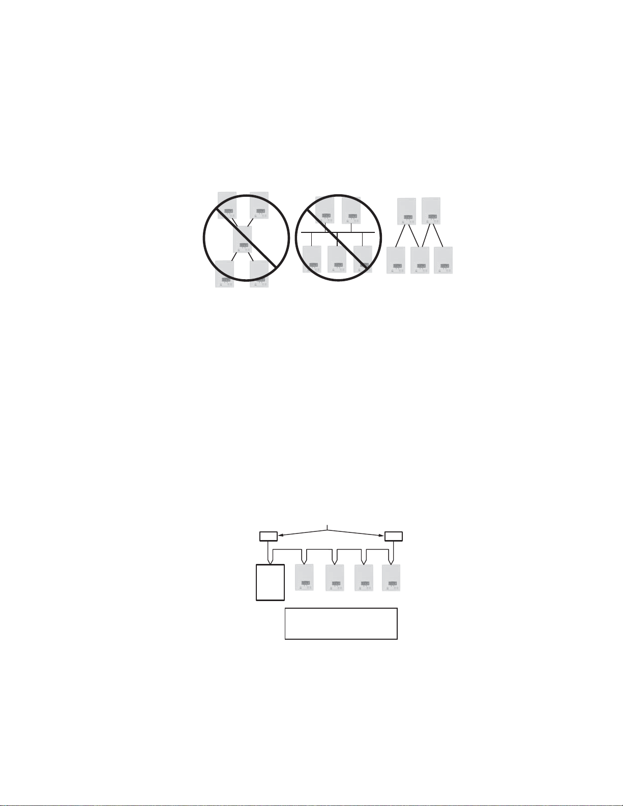
EIA-485 networks use a daisy chain configuration. A daisy chain means that there is only one main cable and every network
device is connected directly along its path.
Figure 1 illustrates two improper network configurations and the proper daisy chain configuration.
Other methods of wiring an EIA-485 network may give unreliable and unpredictable results. There are no troubleshooting
methods for these types of networks. Therefore, a great deal of site experimentation may have to be done, making this a difficult
task with no guarantee of success. Honeywell will only support daisy chain configurations.
Fig. 1. Three different network configurations: star, bus, and daisy chain.
Only the daisy chain configuration is correct for an EIA-485 network.
Maximum Number of Devices
A maximum of 64 nodes is allowed on a single daisy chain segment. A node is defined as any device (controller, thermostat,
repeater, etc.) connected to the RS485 network. Terminators do not count as a node.
NOTE: Biasing is not required with this series of devices.
To determine the number of nodes on a network, add the following:
• One node for each device, including the controller
• One node for each repeater on the chain
For the example in Figure 2, we have one node for the controller, plus 4 for the thermostats for a total of 5 nodes.
If you have more than 64 devices, then repeaters are required to extend the network.
Fig. 2. Five nodes network example.
5 63-4524—02
BACNET INTEGRATION MANUAL FOR TB7200 & TB7300 SERIES THERMOSTATS
EOL
SC
EOL
M32573
LEGEND
EOL: END OF LINE RESISTOR
R: RS485 REPEATER
SC: SUPERVISORY CONTROLLER
EOL
R
EOLEOL
R
EOLEOL
R
EOL
Maximum Cable Length
The maximum length of a chain is related to its transmission speed. The longer the chain, the slower the speed. Using proper
cable, the maximum length of an EIA-485 daisy chain is 4000-ft (1200 m). This will only work reliably for data rates up to 100,000
bps. The maximum data rate is 76,800 bps for TB7200 and TB7300 Series thermostats.
If you require a maximum network length of more than 4000 feet, then repeaters are required to extend the network.
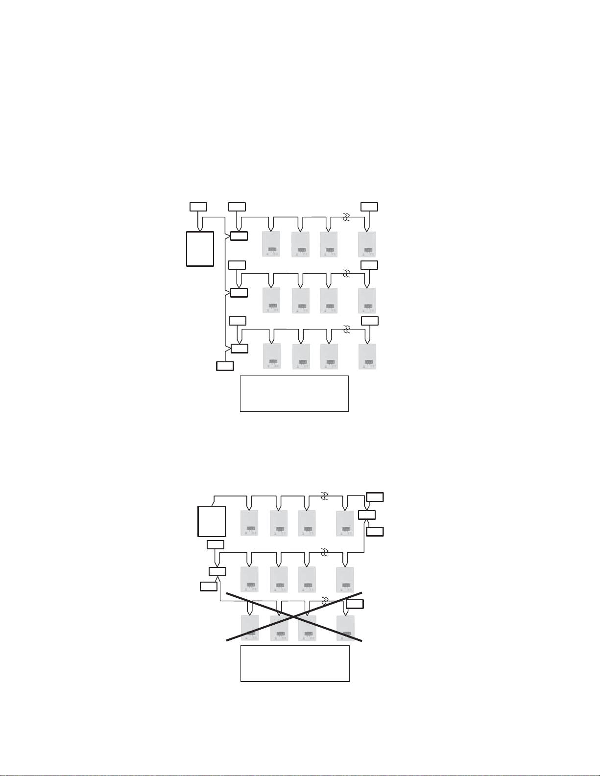
EIA-485 Repeaters
If you have more than 64 devices, or require a maximum network length of more than 4000 feet, then repeaters are required to
extend the network. The best configuration is to daisy chain the repeaters to the controller. From each of these repeaters, a
separate daisy chain will branch off. Figure 3 demonstrates a valid use of repeaters in an EIA-485 network.
Fig. 3. Correct usage – repeaters are daisy chained to the supervisory
controller and separate daisy chains branch from each repeater.
Do not install repeaters in series, as this may result in network reliability problems. Figure 4 demonstrates an incorrect use of a
repeater in an EIA-485 network.
EOL
R
EOL
EOL
M32574
SC
EOL
DO NOT ADD
SECOND
REPEATER
IN SERIES
EOL
R
LEGEND
EOL: END OF LINE RESISTOR
R: RS485 REPEATER
SC: SUPERVISORY CONTROLLER
Fig. 4. Incorrect usage – the second repeater in series may result in an unreliable system.
63-4524—02 6

BACNET INTEGRATION MANUAL FOR TB7200 & TB7300 SERIES THERMOSTATS
End Of Line (EOL) Resistors
MS/TP network must be properly terminated. For daisy chain configurations, you must install an EOL resistor at each end of the
daisy chain. Depending on your MS/TP network configuration, the resistance value of the EOL resistor may change:
• TB7200, TB7300, or TB7600 Series devices are installed at both ends of the MS/TP network:
• 120 Ohms resistor should be installed at each end.
• A TB7200, TB7300, or TB7600 device is installed at one end of the MS/TP network and another device is installed at the other
end:
• Install an End-Of-Line resistor value that matches the other device’s instructions regarding its EOL resistor value;
• Other devices are installed at both ends of the MS/TP network:
• Follow the other device’s instructions regarding its EOL resistor value.
7 63-4524—02
BACNET INTEGRATION MANUAL FOR TB7200 & TB7300 SERIES THERMOSTATS
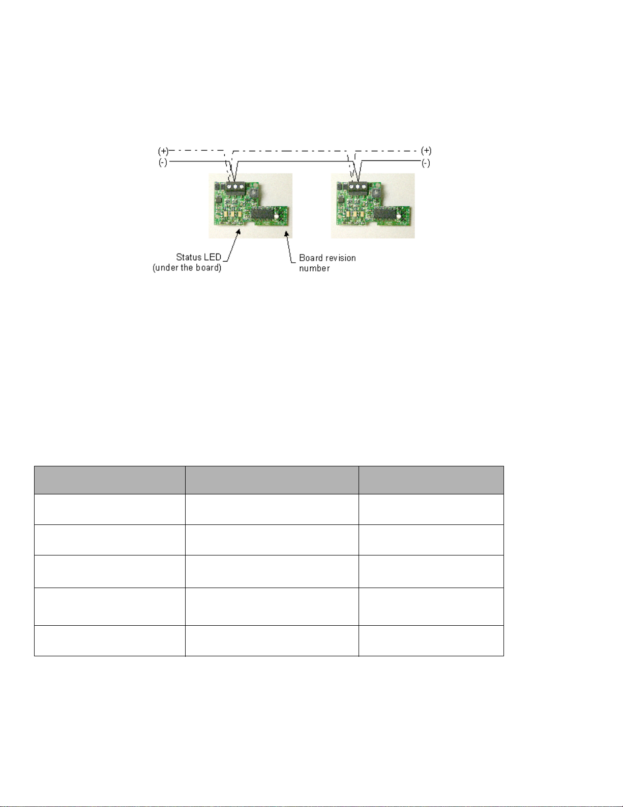
NETWORK ADAPTER
The polarity of the connection to the cable is important. From one module to the other it is important that the same colored wire be
connected to “plus” or “+” and the other colored wire be connected to the “minus” or ”-“. Figure 5 shows the proper MS/TP
connections and the location of the Status LED. This Status LED may help to troubleshoot network problems.
Fig. 5. Correct MS/TP connections and location of a Status LED on a BACnet module
IMPORTANT NOTE: The Ref terminal should NEVER be used to wire shields. The 2 shields from each feed of the network
connection to a thermostat should be wired together in the back of the thermostat and properly protected to prevent any
accidental connection to the ground.
The joined shield connection should then be grounded at a SINGLE point on the whole segment. More than one ground
connection to a shielded wire may induce ground loop noises and affect communication.
Network Adapter Status LED
Table 3 shows the different possibilities with the Status LED behavior for a BACnet module.
Table 3. Status LED condition and possible solutions.
Condition of the Status LED Possible Cause Solution
• 1 short blink
• 2 short blink (no wires
connected to the module)
• 2 short blink (wires connected
to the module)
• 2 short blinks and a longer blink
(wires connected to the
module)
• Right after power is applied: 2
long blinks and then no blinking
BACnet communication NOT active at
default MAC address = 254
The right module has been installed on
the right thermostat model
Module is not at the same baud rate as
the network
The module has detected the presence
of a network
Polarity has been reversed at the
module
Change MAC address to another
value from 0 to 127
N/A
Power off and on the thermostat
N/A
Reverse polarity at the module
63-4524—02 8
BACNET INTEGRATION MANUAL FOR TB7200 & TB7300 SERIES THERMOSTATS
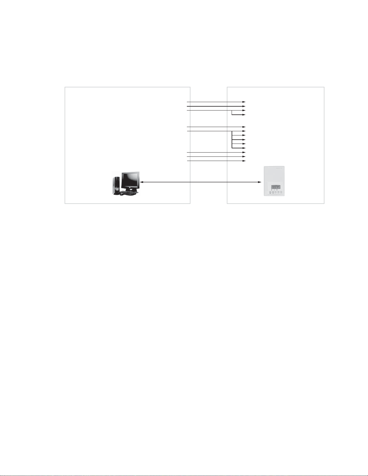
INTEGRATION
Global Commands
The following figure shows which objects from the thermostat can be monitored and commanded from the BAS front-end.
GLOBAL COMMANDS ALL DEVICES
(ALL THERMOSTATS)
OUTDOOR TEMPERATURE AND OUTDOOR HUMIDITY (ENTHALPY)
OUTDOOR TEMPERATURE AND HVAC PLANT CURRENT MODE
GLOBAL COMMANDS SPECIFIC DEVICES
(SPECIFIC AREA THERMOSTATS)
SCHEDULE AND OUTDOOR TEMPERATURE
RESTRICT USER ACCESS TO THERMOSTAT
ROOM TEMPERATURE FOR TESTING AND OVERRIDE
REMOTE CONTROL OF THE AUXILIARY OUTPUT
OUTDOOR TEMPERATURE
SCHEDULE
MSTP NETWORK
OUTDOOR TEMPERATURE (AV9)
DEHUMIDIFICATION LOCKOUT (BV13)
SEQUENCE OF OPERATION (MV15)
SYSTEM MODE (AV16)
OCCUPANCY (MV18)
FAN MODE (MV17)
OCCUPIED HEATING SETPOINT (AV39)
UNOCCUPIED HEATING SETPOINT (AV43)
OCCUPIED COOLING SETPOINT (AV40)
UNOCCUPIED COOLING SETPOINT (AV44)
KEYPAD LOCKOUT (MV19)
ROOM TEMPERATURE (AV7)
AUX OUTPUT (BV14)
BAS FRONT-END
GLOBAL COMMAND CONTROL LEVEL
TB7300 SERIES TSTAT
DEVICE LEVEL
Fig. 6. Global commands from a BAS front-end to a typical TB7300 Series thermostat.
MCR32655
9 63-4524—02
 Loading...