

Honeywell TB7300A5514B, TB7300F5514B, TB7300C5014B, TB7300C5514B, TB7300F5014B Installation Instructions Manual
...
Place Bar Code Here
62-2018-05
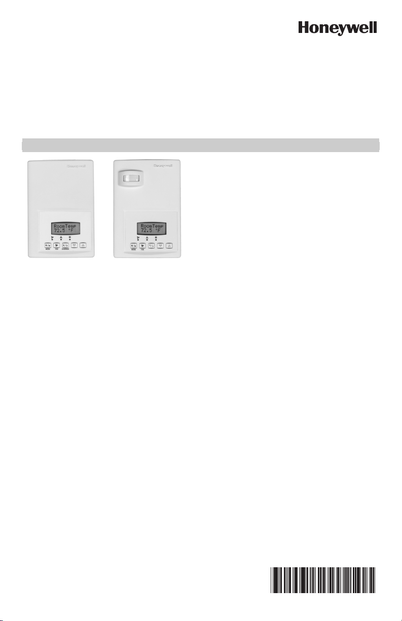
TB7300 Series Communicating
TB7300 Series
Commercial
Thermostat
TB7300 Series Hotel
Thermostat with
Occupancy Sensor
Fan Coil Thermostats
24 VAC/FOR COMMERCIAL AND LODGING HVAC
APPLICATIONS
INSTALLATION INSTRUCTIONS
APPLICATION
The TB7300 PI thermostat family is specifically designed for
fan coil control. The TB7300 Series are communicating
thermostats with models available in BACnet® MS/TP and
ZigBee® wireless mesh protocols and can be easily
integrated into a WEBs-AX building automation system based
on the NiagaraAX® platform.
Thermostats equipped with an occupancy sensor cover
provide advanced active occupancy logic, which will
automatically switch occupancy levels from Occupied to
Stand-By and Unoccupied as required by local activity being
present or not. This advanced occupancy functionality
provides advantageous energy savings during occupied
hours without sacrificing occupant comfort. All thermostats
are PIR ready and can be ordered with or without Honeywell
occupancy sensor. The occupancy sensor cover is available
to order separately if a PIR is needed at a later time.
FEATURES
• Available in BACnet MS/TP and Zigbee wireless protocols
• Backlit LCD display with dedicated function menu keys for simple operation
• Internal humidity sensing for increased occupant comfort through dehumidification on some models
• Fully integrated advanced occupancy functionality with a PIR cover provides energy savings opportunity on
select models; all other models are PIR ready and can have an optional occupancy sensor cover added
• Configurable sequences of operation
• Configurable fan button allows thermostat to meet more applications with a single model
• Password protection to minimize parameter tampering
• Six levels of keypad lockout to limit access to change user parameters such as setpoints, system mode, etc.
• Auto Fan speed mode increases occupant comfort in cooling mode by reducing humidity and reduces fan
noise
• Available for 24 Vac on/off, floating or analog control meets advanced applications requirements
• Three inputs for monitoring and other advanced functions
• SPST auxiliary output that can be used for lighting or auxiliary reheat
• All wiring connections are made to removable terminal blocks simplifying installation
TB7300 SERIES COMMUNICATING FAN COIL THERMOSTATS
TB7300 Series Model Selection
Product Number Description Outputs
BACnet Models
TB7300A5014B Commercial Fan Coil Unit 2 digital + 1 Aux Ready
TB7300A5514B Commercial Fan Coil Unit 2 digital + 1 Aux Yes
TB7300C5014B Commercial Fan Coil Unit 2 floating + 1 Aux Ready
TB7300C5514B Commercial Fan Coil Unit 2 floating + 1 Aux Yes
TB7300F5014B Commercial Fan Coil Unit 2 analog + 1 Aux Ready
TB7300F5514B Commercial Fan Coil Unit 2 analog + 1 Aux Yes
TB7350C5014B Commercial Fan Coil Unit 2 floating + 1 Aux + RH Ready
TB7350C5514B Commercial Fan Coil Unit 2 floating + 1 Aux + RH Yes
TB7350F5014B Commercial Fan Coil Unit 2 analog + 1 Aux + RH Ready
TB7350F5514B Commercial Fan Coil Unit 2 analog + 1 Aux + RH Yes
TB7305A5014B Hotel Fan Coil Unit 2 digital + 1 Aux Ready
TB7305A5514B Hotel Fan Coil Unit 2 digital + 1 Aux Yes
TB7305C5014B Hotel Fan Coil Unit 2 floating + 1 Aux Ready
TB7305C5514B Hotel Fan Coil Unit 2 floating + 1 Aux Yes
TB7305F5014B Hotel Fan Coil Unit 2 analog + 1 Aux Ready
TB7305F5514B Hotel Fan Coil Unit 2 analog + 1 Aux Yes
TB7355C5014B Hotel Fan Coil Unit 2 floating + 1 Aux + RH Ready
TB7355C5514B Hotel Fan Coil Unit 2 floating + 1 Aux + RH Yes
TB7355F5014B Hotel Fan Coil Unit 2 analog + 1 Aux + RH Ready
TB7355F5514B Hotel Fan Coil Unit 2 analog + 1 Aux + RH Yes
Wireless Models
TB7300A5014W Commercial Fan Coil Unit 2 digital + 1 Aux Ready
TB7300A5514W Commercial Fan Coil Unit 2 digital + 1 Aux Yes
TB7300C5014W Commercial Fan Coil Unit 2 floating + 1 Aux Ready
TB7300C5514W Commercial Fan Coil Unit 2 floating + 1 Aux Yes
TB7300F5014W Commercial Fan Coil Unit 2 analog + 1 Aux Ready
TB7300F5514W Commercial Fan Coil Unit 2 analog + 1 Aux Yes
TB7350A5014W Commercial Fan Coil Unit 2 floating + 1 Aux + RH Ready
TB7350A5514W Commercial Fan Coil Unit 2 floating + 1 Aux + RH Yes
TB7350F5014W Commercial Fan Coil Unit 2 analog + 1 Aux + RH Ready
TB7350F5514W Commercial Fan Coil Unit 2 analog + 1 Aux + RH Yes
TB7305A5014W Hotel Fan Coil Unit 2 digital + 1 Aux Ready
TB7305A5514W Hotel Fan Coil Unit 2 digital + 1 Aux Yes
TB7305C5014W Hotel Fan Coil Unit 2 floating + 1 Aux Ready
TB7305C5514W Hotel Fan Coil Unit 2 floating + 1 Aux Yes
TB7305F5014W Hotel Fan Coil Unit 2 analog + 1 Aux Ready
TB7305F5514W Hotel Fan Coil Unit 2 analog + 1 Aux Yes
TB7355C5014W Hotel Fan Coil Unit 2 floating + 1 Aux + RH Ready
TB7355C5514W Hotel Fan Coil Unit 2 floating + 1 Aux + RH Yes
TB7355F5014W Hotel Fan Coil Unit 2 analog + 1 Aux + RH Ready
TB7355F5514W Hotel Fan Coil Unit 2 analog + 1 Aux + RH Yes
Accessories
TB-PIR-FCU FCU Occupancy Sensor Cover
TB-RA-1014 Wireless Remote Antenna Base
TB-RP5000W Wireless Repeater for TB7XXX Series Wireless
TBST-5014W ZigBee Wireless Survey Toolkit
Thermostats
Occupancy
Sensor
1
62-2018—05 2
TB7300 SERIES COMMUNICATING FAN COIL THERMOSTATS
CAUTION
Product Number Description Outputs
TB-VWG-APP-1014 TB7XXX Series Wireless Communication Card
TB-WALL-1014 Room Sensor 10K NTC Type 2
TB-WALLOVR-1014 Room Sensor with Override 10K NTC Type 2
1
Thermostats ordered without an occupancy sensor cover can be retrofitted with an occupancy sensor cover later if
needed.
Occupancy
Sensor
More Information
We recommend downloading the appropriate integration reference document (wireless or BACnet) and if installing
thermostats with occupancy sensor covers, then also downloading the PIR Application Guide before you begin
installation. All documentation is available on http://customer.honeywell.com.
— BACnet Integration Manual for TB7200 and TB7300 Series Thermostats (Form No. 63-4524)
— Wireless Installation and Integration Reference Guide for TB7200, TB7300, and TB7600 Thermostats
(Form No. 63-4522)
— PIR Application Guide for TB7200 and TB7300 Series Thermostats (Form No. 63-4526)
— Sensors Product Overview Brochure (Form 63-9285) provides a complete listing of 10K NTC Type II sensors.
INSTALLATION AND WIRING
Mounting Locations
• Do not install on an outside wall.
• Must be installed away from any heat source.
• Should not be installed near an air discharge grill.
• Should not be mounted in direct sun radiation.
• Nothing must restrain vertical air circulation to the thermostat.
• Wall surface must be flat and clean.
IMPORTANT
• If replacing an old thermostat, label the wires before removal of the old thermostat.
1
• Electronic controls are static sensitive devices. Discharge yourself properly before manipulation and installing
the thermostat.
• Short circuit or wrong wiring may permanently damage the thermostat or the equipment.
• Anti-short cycling can be set to 0 minutes for equipment that has an anti-cycling timer. Do not set to 0 unless
the equipment has internal anti-cycling timer or damage to equipment can occur.
• All TB7300 Series thermostats are to be used only as operating controls. Whenever a control failure could
lead to personal injury and/or loss of property, it becomes the responsibility of the user to add safety devices
and/or alarm system to protect against such catastrophic failures.
3 62-2018—05
TB7300 SERIES COMMUNICATING FAN COIL THERMOSTATS
°C
°F
M21300
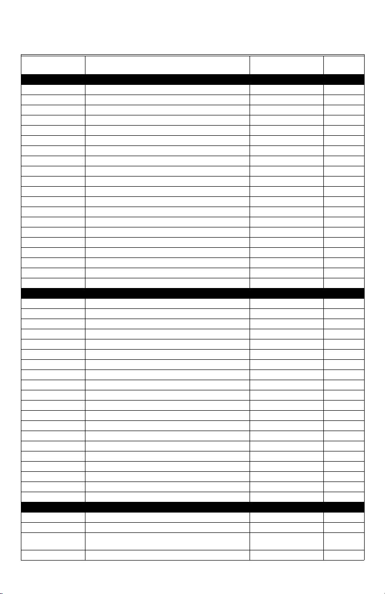
Fig. 1. Remove cover of thermostat
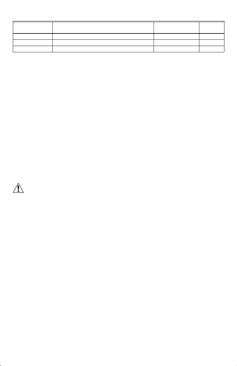
Fig. 2. Location of PCB retaining tabs and
mounting screws
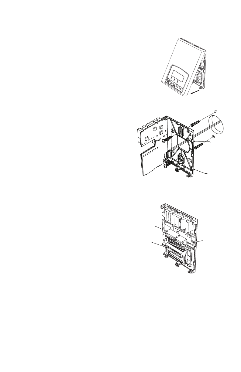
TOP LEFT
5 POLE
CONNECTOR
BOTTOM
8 POLE
CONNECTOR
TOP RIGHT
3 POLE
CONNECTOR
M21302
Fig. 3. Re-install terminal blocks
Thermostat Installation
1. Open up by pulling on the bottom side of thermostat.
(Fig. 1)
2. Remove wiring terminals.
3. Open the thermostat PCB to the left by pressing the PCB
retaining tabs. (Fig. 2).
4. Pull cables 6 inches out of the wall.
5. Thread cable through the central hole of the base.
6. Align the base and mark the location of the two mounting
holes on the wall. Install proper side of base up.
7. Install anchors in the wall.
8. Insert screws through the mounting holes on each side of
the base and mount base on wall. (Fig. 2).
9. Gently swing back the circuit board back to the base and
push on it until the tabs lock it in place.
10. Strip each wire 1/4 inch.
PCB
RETAINING
TABS
PCB
RETAINING
TABS
M21301
11. Wire the terminals for the desired application. See Table 1
for terminal descriptions and wiring diagrams.
12. Gently push back excess cable into hole.
13. Install wiring terminals in correct location (Fig. 3).
14. Reinstall the cover (top first).
15. Install security screw.
62-2018—05 4
TB7300 SERIES COMMUNICATING FAN COIL THERMOSTATS
BI 1
RS
Scom
BI 2
UI 3
REMOTE
WALL SENSOR
CONTACT
—REM NSB
—MOTION
—WINDOW
SS (SUPPLY SENSOR)
COS (CHANGEOVER
SENSOR)
COC/NH
—NORMALLY HEAT
—CLOSED CONTACT = COLD WATER
COC/NC
—NORMALLY COOL
—CLOSED CONTACT = HEAT WATER
CONTACT
—DOOR
—REMOTE OVERRIDE
—FILTER ALARM
—SERVICE ALARM
OR
M16948
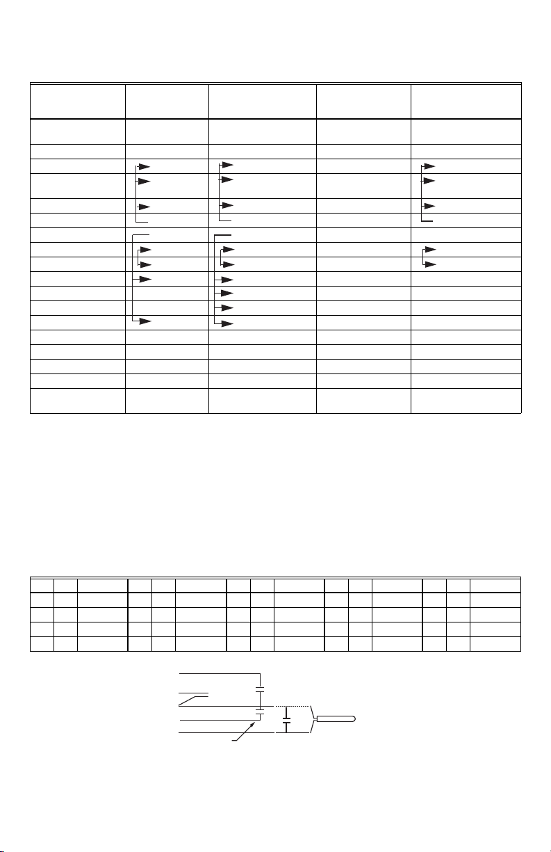
Thermostat Terminals
Table 1. Terminal identification
Terminal
Description
Internal
Temperature
TB73xxA5x14(x)
2 and 4 Pipe on/
off
XXInternal
Internal Humidity Model Dependent Internal Humidity Model Dependent
1- High Fan Speed Fan-H Fan-H 1- High Fan Speed Fa n-H
2- Medium Fan
Speed
Fan-M Fan-M 2- Medium Fan
3- Low Fan Speed Fan-L Fan-L 3- Low Fan Speed Fan-L
4- 24 V~ Hot 24 V~ Hot 24 V~ Hot 4- 24 V~ Hot 24 V~ Hot
5- 24 V~ Com 24 V~ Com 24 V~ Com 5- 24 V~ Com 24 V~ Com
6- Aux BO 5 BO 5-Aux BO 5-Aux 6- Aux BO 5 BO 5-Aux
7- Aux BO 5 BO 5-Aux BO 5-Aux 7- Aux BO 5 BO 5-Aux
8- BO 3 Open Heat BO 3 BO 3 Blank
9- BO 4 Close Heat BO 4 9- AO 2 Heat AO 2
10- BO 1 Open Cool BO 1 10- AO 1 Cool AO 1
11- BO 2 Close Cool BO 2 BO 2 Not used Blank Blank
12- BI #1 BI 1 BI 1 12- BI #1 BI 1
13- RS RS RS 13- RS RS
14- Scom Scom Scom 14- Scom Scom
15- BI #2 BI 2 BI 2 15- BI #2 BI 2
16- UI #3 COS/COC/
SS
For information on configuration options for the binary inputs (B1 and B2) and the universal input (U3) see Table 11.
Configuration Parameters.
UI 3 UI 3 16- UI #3 COS/COC/
TB73xxC5x14(x)
2 and 4 Pipe floating
2 and 4 Pipe on/off
Ter mina l
Description
Tem per atu re
Speed
SS
TB73xxF5x14(x)
2 and 4 Pipe analog
X
Fan-M
UI 3
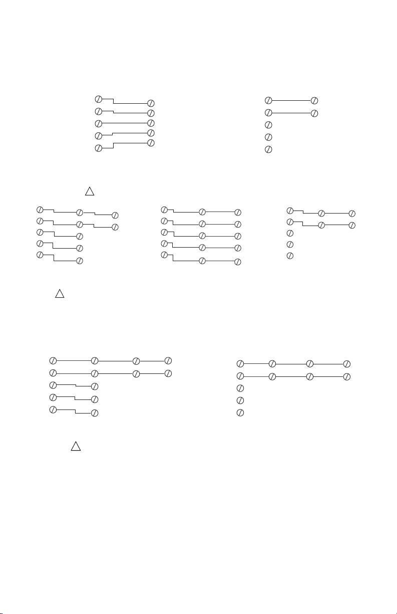
Sensor Wiring for all Thermostat Models
Remote sensors
Remote mount temperature sensors use 10K type 2 NTC thermistors. See Remote Inputs wiring diagram below for
wiring information.
• Each sensor can be configured for various averaging combinations
• Optional occupancy led
• Optional override key
• Remote mount temperature sensors use 10K type 2 NTC thermistors.
Table 2. Temperature vs Resistance for 10 Kohm NTC thermistor (R
ºF ºC Kohm ºF ºC Kohm ºF ºC Kohm ºF ºC Kohm ºF ºC Kohm
-40 -40 324.3197 -4 -20 94.5149 32 0 32.1910 68 20 12.4601 104 40 5.3467
-31 -35 234.4009 5 -15 71.2430 41 5 25.1119 77 25 10.0000 113 45 4.3881
-22 -30 171.3474 14 -10 54.1988 50 10 19.7390 86 30 8.0694 122 50 3.6202
-13 -25 126.6109 23 -5 41.5956 59 15 15.6286 95 35 6.5499 131 55 3.0016
Fig. 4. Remote input
5 62-2018—05
= 10KW±3%, B
25°C
25/85°C
= 3975K±1.5%)
TB7300 SERIES COMMUNICATING FAN COIL THERMOSTATS
A
Scom
RS
AUX
C
DI
Scom
RS
TB-WALLOVR-1014 TB-WALL-1014
DIP SWITCHES
S1 = ON
S2 = OFF
DIP SWITCHES
S1 = ON
S2 = OFF
REMOTE WIRING 2 SENSORS
M32848A
Scom
RS
TB-WALL-1014
Scom
RS
TB-WALL-1014
TB-WALL-1014 AND TB-WALLOVR-1014 CAN BE MIXED AND MATCHED
TB-WALL-1014 AND TB-WALLOVR-1014 ARE TO BE WIRED IN PARALLELL
ENSURE THE DIP SWITCH SETTINGS ARE CORRECT IN EACH REMOTE SENSOR
1
1
Scom
RS
AUX
C
DI
TB-WALLOVR-1014
DIP SWITCHES
S1 = ON
S2 = OFF
Scom
RS
AUX
C
DI
TB-WALLOVR-1014
TB7200/TB7300
THERMOSTAT
TB7200/TB7300
THERMOSTAT
TB7200/TB7300
THERMOSTAT
DIP SWITCHES
S1 = ON
S2 = OFF
DIP SWITCHES
S1 = ON
S2 = OFF
DIP SWITCHES
S1 = ON
S2 = OFF
Scom
RS
BO 5
24 VAC
COM
BI 2
Scom
RS
BO 5
24 VAC
COM
BI 2
Scom
RS
BO 5
24 VAC
COM
BI 2
Scom
RS
AUX
C
DI
TB-WALLOVR-1014
DIP SWITCHES
S1 = OFF
S2 = OFF
ALL DIP SWITCHES
S1 = OFF
S2 = OFF
REMOTE WIRING 3 SENSORS
M32849A
Scom
RS
TB-WALL-1014
Scom
RS
TB-WALL-1014TB-WALL-1014TB-WALL-1014
Scom
RS
TB-WALL-1014
TB7200/TB7300
THERMOSTAT
TB7200/TB7300
THERMOSTAT
Scom
RS
Scom
RS
Scom
RS
BO 5
24 VAC
COM
BI 2
Scom
RS
BO 5
24 VAC
COM
BI 2
DIP SWITCHES
S1 = OFF
S2 = OFF
TB-WALL-1014 AND TB-WALLOVR-1014 CAN BE MIXED AND MATCHED
TB-WALL-1014 AND TB-WALLOVR-1014 ARE TO BE WIRED IN PARALLELL
ENSURE THE DIP SWITCH SETTINGS ARE CORRECT IN EACH REMOTE SENSOR
1
If LED indicator is desired at the TB-WALL-OVR-1014:
1. Set the Aux Cont installer parameter (which controls BO5) to option 2, Auxiliary NC.
2. Install a jumper across the BO5 terminal and 24 Vac Hot.
REMOTE WIRING 1 SENSOR
TB7200/TB7300
THERMOSTAT
Scom
RS
BO 5
24 VAC
COM
BI 2
TB-WALLOVR-1014 TB-WALL-1014
Scom
RS
AUX
C
DI
DIP SWITCHES
S1 = ON S2 = ON
TB7200/TB7300
THERMOSTAT
Scom
RS
BO 5
24 VAC
COM
BI 2
Fig. 5. Wiring example of single remote wall mounted room sensor
Scom
RS
DIP SWITCHES
S1 = ON S2 = ON
M32847
Fig. 6. Wiring examples of two remote wall mounted room sensors for averaging applications
Fig. 7. Wiring examples of three remote wall mounted room sensors for averaging applications
62-2018—05 6
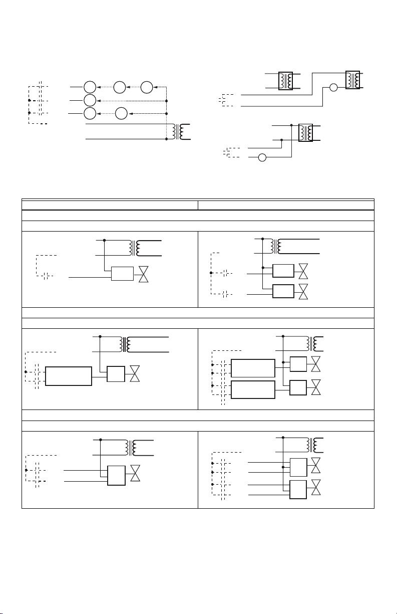
Fan and Auxiliary Output Wiring
24 V~ HOT
24 V ~ COM
HEATING/COOLING VALVE
BO1
BO2
IF N.O.
IF N.C.
24 VAC
COM
OR
M16924
24 V~ HOT
24 V ~ COM
HEATING VALVE
COOLING VALVE
BO3
BO4
BO1
BO2
IF N.O.
IF N.C.
24 VAC
COM
24 VAC
COM
OR
IF N.O.
IF N.C.
OR
M16917
24 V~ HOT
24 V ~ COM
HEATING/COOLING VALVE
BO1
BO2
OPEN
COM
CLOSE
M16925
24 V~ HOT
24 V ~ COM
HEATING VALVE
COOLING VALVE
BO3
BO4
BO1
BO2
OPEN
COM
CLOSE
OPEN
COM
CLOSE
M16918
TB7300 SERIES COMMUNICATING FAN COIL THERMOSTATS
3 SPEED 2 SPEED
FAN-H
FAN-M
FAN-L
HIGH
MED
LOW
24 V ~ HOT
24 V ~ COM
24 V~ TRANSFORMER RELAY PACK
Fig. 8. Power fan Fig. 9. Auxiliary output
Main outputs wiring
2 Pipe applications 4 Pipe applications
24 V~ HOT
24 V ~ COM
24 VAC
BO 2
TB7300C5x14(x), TB7305C5x14(x), TB7350C5x14(x) and TB7355C5x14(x)
COM
SINGLE
SPEED
HIGH
HIGH
LOW
M16947
On/Off control
TB7300A5x14(x) and TB7305AC5x14(x)
N.C. HEATING/
COOLING VALVE
M16960
On/Off control
DRY CONTACT TO END DEVICE 24 V~ MAXIMUM
#4 24 V~ HOT
#5 24 V~ COM
#6
#7
24 VAC POWER TO RELAY
#4 24 V~ HOT
#5 24 V~ COM
#6
#7
R
24 V~ HOT
24 V ~ COM
BO 3
BO 2
24 VAC
COM
24 VAC
COM
N.O. HEATING VALVE
N.C. COOLING VALVE
R
M16949
M16961
TB7300C5x14(x), TB7305C5x14(x), TB7350C5x14(x) and TB7355C5x14(x)
Floating control
7 62-2018—05
TB7300 SERIES COMMUNICATING FAN COIL THERMOSTATS
24 V~ HOT
24 V ~ COM
HEATING/COOLING VALVE
AO 1
COM
24 VAC
0-10 VDC
M16926
24 V~ HOT
24 V ~ COM
HEATING VALVE
COOLING VALVE
AO 2
AO 1
COM
24 VAC
0-10 VDC
COM
24 VAC
0-10 VDC
M16919
ROOM TEMPERATURE
CONTROL THERMOSTAT
3 SPEED FAN
M16950
ROOM TEMPERATURE
CONTROL THERMOSTAT
3 SPEED FAN
M16950
24 VAC FAN RELAYS
HIGH
MED
LOW
FAN-H
FAN-M
FAN-L
UI 3 COS
24 V~ COM
24 V ~ HOT
BO 2 CLOSE
BO 1 OPEN
OPTIONAL SUPPLY WATER
TEMPERATURE SENSOR
M16954
2 Pipe applications 4 Pipe applications
Analog control
TB7300F5x14(x), TB7305F5x14(x), TB7350F5x14(x) and TB7355F5x14(x)
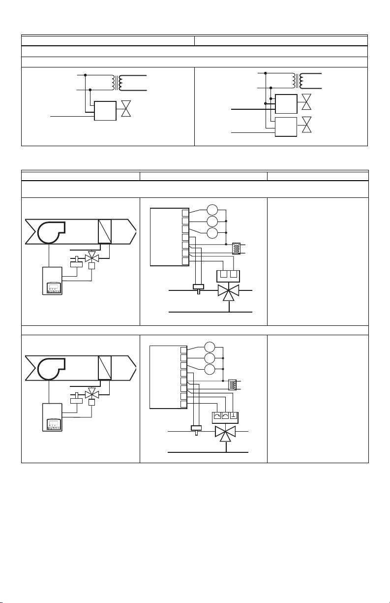
Typical applications
2 pipe system cooling and/or heating: TB7300A5x14(x), TB7300C5x14(x) and TB7305C5x14(x) on/off N.C.
Schematic Wiring Settings
actuator
Normally closed on/off valve
cooling and/or heating
UI 3 COS
24 V~ COM
24 V ~ HOT
BO 2 N.C.
24 VAC FAN RELAYS
FAN-H
FAN-M
FAN-L
OPTIONAL SUPPLY WATER
TEMPERATURE SENSOR
HIGH
MED
LOW
Mandatory
•Pipe no = 2 pipes
•CntrltTyp = On/Off
•Fan Menu = 0 (L-M-H)
•FL time = as per actuator
If cooling only set:
• SeqOpera = 0 Cooling only
If heating only set:
• SeqOpera = 1 Heating only
If heat/cool auto-changeover
with a local water temperature
sensor set:
• SeqOpera = 0 Cooling only
M16953
•UI3 = COS
2 pipe system cooling and/or heating: TB7300C5x14(x) and TB7305C5x14(x) floating actuator
Modulating floating valve
cooling and/or heating
Mandatory
•Pipe no = 2 pipes
•CntrltTyp = Floating
•Fan Menu = 0 (L-M-H)
•FL time = as per actuator
If cooling only set:
• SeqOpera = 0 Cooling only
If heating only set:
• SeqOpera = 1 Heating only
If heat/cool auto-changeover
with a local water temperature
sensor set:
• SeqOpera = 0 Cooling only
•UI3 = COS
62-2018—05 8
 Loading...