

Page 1
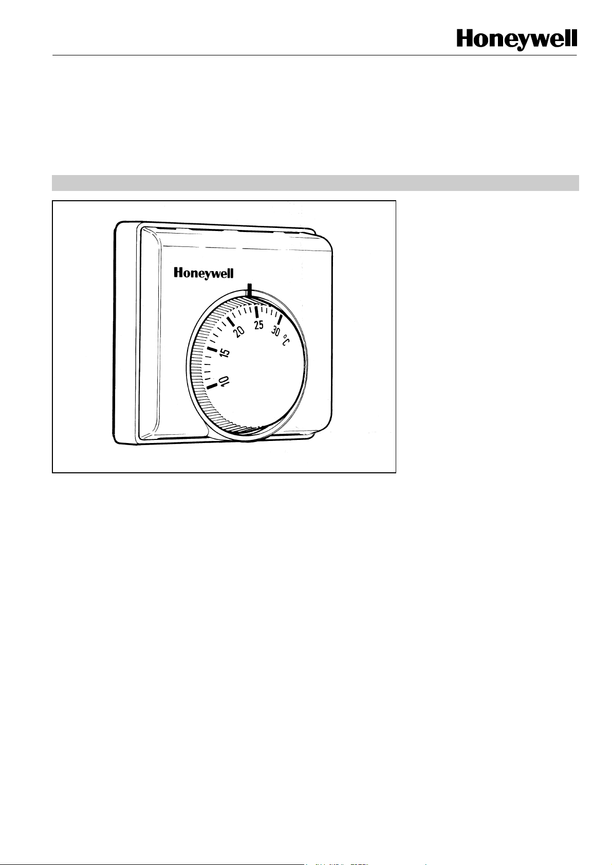
T8360
24 VOLT ROOM THERMOSTAT
PRODUCT SPECIFICATION SHEET
The T8360 low voltage room
thermostat has S.P.S.T. On/Off output
for control of oil or gas boilers, zone
valves, warm air or hydronic central
heating systems with low voltage
control circuits.
FEATURES
• Dual diaphragm sensing element ensures close
temperature control for all loads and applications
• Attractive modern styling makes this thermostat ideal
for locating in the living space
• Series heat anticipator allows 2-wire connection for
operation at current range 90 to 130mA
• Mounts directly onto wall or conduit box
• Easy-to-wire terminals with built-in conductor clamps
to ensure wiring is retained securely
• Double insulated. No earth wire required for
operation.
• Optional extras available are:
– range stops F42006646-001
– tamperproof cover F42007110-001 (opaque) or
F42007110-002 (transparent)
– additional wallplate for special mounting
requirements F42007789-001
EN0R8538 R0 2004
Page 2
T8360 24 VOLT ROOM THERMOSTAT
SPECIFICATIONS
Switch type : T8360 S.P.S.T. (Heating)
Electrical ratings : 24Vac, +10%, -15% 50…60Hz
Anticipator
Temperature setting range : 10 to 30
Terminals : Terminals sized to accept up to 2 x single or multi-stranded wires from
Performance : Maximum differential 1.0
Switch life : Greater than 100,000 operations (all loads) for main switch.
Environmental requirements : Operating temperature range 0 to 40
Approvals : CE mark, complying with standards EN60730-1 (1995), EN55014-1 (1997),
Ordering Specification : T8360A1000
: Gold-plated contacts, 127 mA maximum at 24 Vac
: Optimum rating 110 mA (+15%, -20%), anticipator connected
: Possible rating 10 - 500 mA , anticipator not connected
: In series with load, value 18 ohms
1.0 mm
Each terminal has a conductor clamp for securing the wiring conductor and is suitable
for both blade and cross-head screwdrivers.
connected.
: Typical differential 0.5
Shipping and storage range -20 to 50
Humidity range 0 to 90% R.H. (non-condensing)
EN55014-2 (1996).
Product must be wired as shown for CE compliance.
o
C
2
to 2.5 mm
2
o
C at 20oC at heat ramps of 3oC per hour, with anticipator
o
C.
o
C
o
C
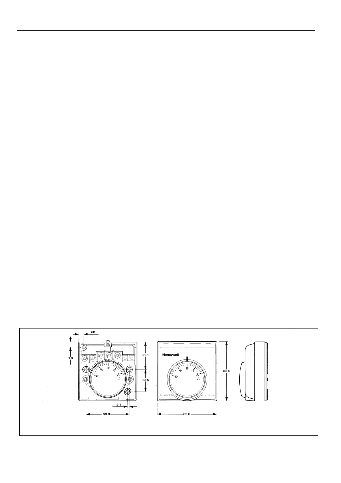
DIMENSIONS
EN0R8538 R0 2004 2
Page 3

T
INSTALLATION
IMPORTAN
1. The installer must be a trained service engineer
2. Disconnect the power supply before beginning
installation
Location
A T8360 room thermostat is the temperature control element
in your heating system and must be located in a position with
good air circulation at average temperature - on an inside
wall about 1.5 m above the floor.
Do not position the thermostat in draughts, near hot or cold
air from water pipes or radiant heat from the sun or
appliances.
T8360 24 VOLT ROOM THERMOSTAT
Mounting the thermostat
The T8360 can be mounted directly on the wall or on a
conduit box (see Fig. 2). Mounting screws are provided for
both alternatives.
An additional wall-plate is available for special mounting
requirements.
Wiring the thermostat
The standard wiring access is via a hole in the base of the
thermostat, near the top edge. There are also 4 breakouts
on the cover (2 on top and 2 on the sides) for surface wiring
requirements.
Wall box mounting Surface mounting
screws supplied
Fig.2 Mounting the Thermostat
OPERATION
Sensing Element
The thermostat sensing element comprises two circular,
flexible metal plates welded together at the rims
encapsulating a small quantity of gas in liquid form, whose
pressure changes greatly in response to small variations in
temperature. In effect, this dual diaphragm forms a 'bellows'
which expands/contracts in sympathy with the ambient
temperature changes - this movement serving to operate a
snap acting switch rated to control the heating or cooling
circuit.
Use wall box fixing holes
or alternatives shown
screws supplied
Disposal of Thermostat
The thermostat contains no user serviceable parts. Please
ensure product disposal is in a safe and environmentally
friendly manner, in compliance with local regulations. Do not
dispose of in a fire.
Series Heat Anticipator
It is recommended that the series heat anticipator is used for
systems with a high heating ramp rate. This will overcome
the overshoot and undershoot problems often found in this
type of installation. The 18ohm anticipator is in series with
the load, ensuring a 2-wire connection only is required.
However, this is suitable only for loads in the range 90 to
130mA.
For loads outwith the range 90 to 130mA, the 24Vac input
should be connected via terminal 1, so as to bypass the
series anticipator. If this is done, loads from 10 to 500mA
can be switched.
EN0R8538 R0 2004 3
Page 4

T8360 24 VOLT ROOM THERMOSTAT
WIRING
SERIES ANTICIPATOR : LOADS 90 – 130mA
SERIES ANTICIPATOR : LOADS 90 – 130mA
T8360A1000
T8360A1000
90 – 130mA
90 – 130mA
18R
18R
24 V
24 V
HEATING LOAD
HEATING LOAD
3
3
2
2
1
1
NO ANTICIPATOR : LOADS 10 – 500mA
NO ANTICIPATOR : LOADS 10 – 500mA
24 V
24 V
T8360A1000
T8360A1000
10 – 500mA
10 – 500mA
3
3
2
2
1
1
HEATING LOAD
HEATING LOAD
Honeywell Control Systems Limited
Newhouse Industrial Estate
Motherwell ML1 5SB
United Kingdom
EN0R8538 R0 2004
http://europe.hbc.honeywell.com
 Loading...