

Page 1
LOW VOLTAGE MODULATING CONTROLLER
y
g
g
g
g
g
y
y
y
y
APPLICATIONS
The T8078C digital electronic controller is designed for
individual zone control of terminal units in fan coil and
air conditioning systems.
The controller provides position control of valves or
dampers (for airside control), and is capable of
mounting on a switching sub-base for manual control
of the fan speed.
T8078C has great applications flexibility built-in – all
applications and control modes can be selected simpl
bysettinga bank of switches inside the product.
Control parameters are also adjusted by means of onboard switches.
T8078C also supports a number of features that
enhance the applications capability. These include
remote sensin
an external input), remote setpoint adjustment, and
heat/cool changeover.
Installation and commissionin
special fast commissionin
internal valve synchronisation, simple user dia
LED indication, and the provision of a dia
output.
, energysavings mode (activated from
are assisted bya
checkout sequence,
nostic
nostic
T8078C
PRODUCT SPECIFICATION SHEET
FEATURES
• Modern styling makes T8078C ideal for locating in
the occupied space, particularly in offices and
hotels.
• Proportional + Integral (P+I) control form ensures
close temperature control under all operating
conditions.
• Control modes and applications configured by onboard switches.
• Choice of control Modes:
- 3-position modulating
- thermal predictive modulating (TPM)
- On/off
• Choice of Applications:
- 2-pipe fan-coil cooling
- 2-pipe fan-coil heating
- 2-pipe fan-coil cooling +2-stage on/off heating
- 2-pipe fan-coil heating +2-stage on/off cooling
- 2-pipe fan-coil heat/cool changeover
- 4-pipe fan-coil heat + cool in sequence
• Choice of control parameters:
- 1, 2, or 4 K for the Proportional Band
- 2, 4 K for the Zero Energy Band
• Automatic heat/cool changeover is achieved b
using a remote switch, or a pipe thermostat
(S4390A1004) on the supply water pipe.
• Control setpoint can be remotely adjusted by ±±±±5K.
• Energy Savings Input - a local contact closure or a
central voltage input will switch T8087C to Energ
Savings Mode, where the cooling and heating
setpoints will change to pre-defined setup and
setback temperatures, enabling maximum energ
efficiency. Setup/setback values can be set 2-8K b
means of an on-board potentiometer.
• Sensor options: On-board or external (Wall
mounted, or Remote/return air). The connection of
an external sensor is detected automatically.
• Valve commissioning sequence for fast system
check.
• Periodic valve exercise and synchronisation.
• Simple user diagnostics capability – by means of a
flashing LED mounted inside the thermostat cover.
• Diagnostic output – for communication of
diagnostic system information to a PC tool.
• Extra wide Input Voltage Specification : 18 – 30 Vac.
• Automatic calibration offset over full voltage range.
• Suitable for mounting either on the terminal unit or
on the wall (surface or wall-box mounting).
• Wiring access from the rear, and surface wiring
knockouts at the top and sides.
• Locking front cover.
1 EN0R8535 R1 2003
Page 2

INDEX OF CONTENTS
Page Contents
1 APPLICATIONS OVERVIEW
1 FEATURES OVERVIEW
3 SPECIFICATIONS
4 PRODUCT APPLICATIONS TABLE
4 SYSTEM ARCHITECTURE
5 OPERATION
5 Control Modes
5 Operating Modes
5 Comfort Mode
5 Energy Savings Mode
6 Startup & Commissioning
7 Diagnostics & Fault Indication
8 ORDERING INFORMATION
8 SYSTEM & PARAMETER SELECTION SWITCHES
8 How to Configure T8078C
9 INSTALLATION
9 Location
9 Mounting
9 Wiring
9 Layout & Terminal Connections
10 APPLICATIONS – MODULATING CONTROL
10 (1) Modulating Cooling
10 (2) Modulating Heating
11 (3) Modulating Cooling + 2-Stage On/Off Heating
11 (4) Modulating Heating + 2-Stage On/Off Cooling
12 (5) Modulating Heat / Cool Changeover
12 (6) Modulating Cooling + Heating Sequence
13 APPLICATIONS – ON/OFF CONTROL
13 (7) On/Off Cooling
13 (8) On/Off Heating
14 (9) On/Off Cooling + 2-Stage On/Off Heating
14 (10) On/Off + 2-Stage On/Off Cooling
15 (11) On/Off Heat / Cool Changeover
15 (12) On/Off Cooling + Heating Sequence
16 APPLICATIONS – TPM CONTROL (THERMO-ELECTRIC ACTUATORS)
16 (13) TPM Cooling
16 (14) TPM Heating
17 (15) TPM Cooling + 2-Stage On/Off Heating
17 (16) TPM Heating + 2-Stage On/Off Cooling
18 (17) TPM Heat / Cool Changeover
18 (18) TPM Cooling + Heating Sequence
19 ADDITIONAL FEATURES
19 Auto Heat / Cool Changeover
19 Remote Temperature Sensing
20 Remote Setpoint Adjustment
20 SUITABLE VALVES & ACTUATORS
20 OPTIONAL ACCESSORIES
2 EN0R8535 R1 2003
Page 3
SPECIFICATIONS
Power Supply:
Power Consumption:
Output Load Rating:
Setpoint Range:
Configuration/System Selection:
Control Modes:
Applications Systems:
Proportional Band (Xp):
Zero Energy Band (ZEB):
Interstage Differential (ID):
Control Point Stability:
Ambient Temperature Range:
Storage Temperature Range:
Relative Humidity:
Remote Setpoint Adjustment:
Energy Savings (Setup/Setback):
Heat/Cool Changeover:
Mounting:
Wiring:
Enclosure:
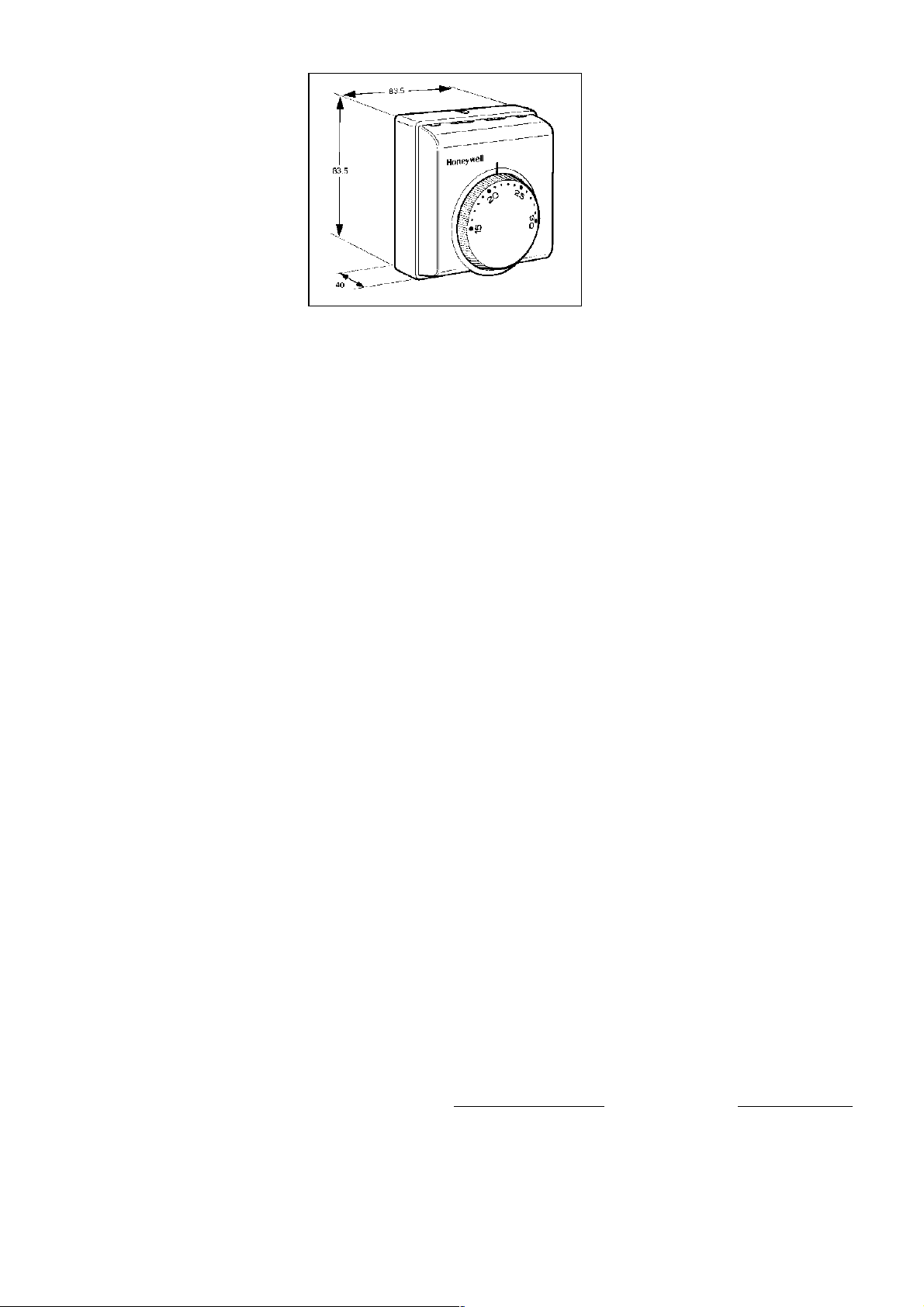
Dimensions:
Protection Class:
Approvals:
Sensors:
24 Vac nominal 50/60Hz, operating range 18 – 30 Vac
1.2 VA nominal (electronics only)
0.3 A (maximum) for all outputs at 24 Vac, with solid state switching
15 to 30 °C
Made via a bank of 6 on-board dip switches
3 different Control Modes :-
Modulating : 3-position modulating P+I control, based on adjustable proportional Band
(Xp), and 150sec valve run-time
On/Off : Primary stage control is P+I on/off output based on adjustable
Proportional Band (Xp) and a fixed cycle rate (6 cycles/hour Cooling, 6
cycles/hour heating)
: Secondary stage control is P+I on/off output based on a fixed Proportional
Band of 1K and a fixed cycle rate (6 cycles/hour Cooling, 12 cycles/hour
heating)
TPM : Special on/off control mode for thermo-electric actuators
6 different Applications System types :-
• Heat / Cool Changeover
• Cooling Only
• Cooling + optional 2-stage On/off Heating
• Heating Only
• Heating + optional 2-stage On/off Cooling
• Heating + Cooling Sequence Control
1K, 2K, or 4K (depending on system) selected using DIP switches
1K for secondary 2-stage Heating or Cooling stage control
2K or 4K selected using DIP switches
Fixed at 1K, for Systems with secondary 2-stage Heating or Cooling
±0.5K at 20°C
Operating range 0 to 40 °C
-20to55°C
10 to 90%, non condensing
±5K by remote unit, resistance input (Q979B1029, Q979C1036)
2 to 8K setup/setback possible, by means of external contact closure input
Value set by potentiometer on T8078C
Contact closure can be local or central, to control a group of T8078C (up to 50 max)
Automatic changeover by means of external contact closure input
Input can be local (from aquastat) or central from switch/relay (controls up to 50 max)
Directly onto wall or wall-box (65x65mm junction box with 60mm screw pitch) or inside
terminal unit or fan-coil
Also mounts on fan speed subbase Q6360A1025
Mounting accessory F42007789 available for other mounting configurations
14 x screw terminals capable of accepting up to 1.5mm² stranded cable
Max length of wiring to actuators is 100m @ 1.0mm², 150m @ 1.5mm²
Flame retardant plastic housing
83.5 x 83.5 x 40 mm
IP30 (IEC144)
CE mark, conforming as follows :
Directive (Amendments)
73/23/EEC (93/68/EEC) EN60730-1:2001
89/336/EEC (93/68/EEC & 92/51/EEC) EN55014-1:1997
On-board sensor , type NTC100K
Remote sensor T8109C1002 (1.5m cable) auto detected on power-up
Maximum sensor extension is 20m (using screened cable)
Standards Applied
EN60730-2-9:1995
EN55014-2:1997
3 EN0R8535 R1 2003
Page 4
PRODUCT APPLICATIONS
Basic Application Controlled Device Control Mode – details of application Application No.
2-pipe fan-coil Valve control Modulating cooling 1
“ Modulating heating 2
“ On/off cooling 7
“ On/off heating 8
“ TPM cooling (thermo-electric actuator) 13
“ TPM heating (thermo-electric actuator) 14
Airside control (damper) Modulating cooling 1
“ Modulating heating 2
Terminal unit Damper control Modulating cooling 1
“ Modulating heating 2
2-pipe fan-coil with auxillary electric heat Valve control Modulating cooling + 1or 2-stage on/off heating 3
(1 or 2-stage electric heating elements) “ On/off cooling + 1or 2-stage on/off heating 9
“ TPM cooling + 1or 2-stage on/off heating 15
Airside control (damper) Modulating cooling + 1or 2-stage on/off heating 3
2-pipe fan-coil with auxillary cooling Valve control Modulating heating + 1or 2-stage on/off cooling 4
(1 or 2-stage chillers) “ On/off heating+ 1or 2-stage on/off cooling 10
“ TPM heating + 1or 2-stage on/off cooling 16
Airside control (damper) Modulating heating + 1or 2-stage on/off cooling 4
2-pipe fan-coil with heat/cool changeover Valve control Modulating heat/cool changeover 5
“ On/off heat/cool changeover 11
“ TPM (thermo-electric actuator) heat/cool
changeover
4-pipe fan-coil Valve control Modulating cooling + heating in sequence 6
“ On/off cooling + heating in sequence 12
“ TPM cooling + heating in sequence 18
Airside control (damper) Modulating cooling + heating in sequence 1 or 2
17
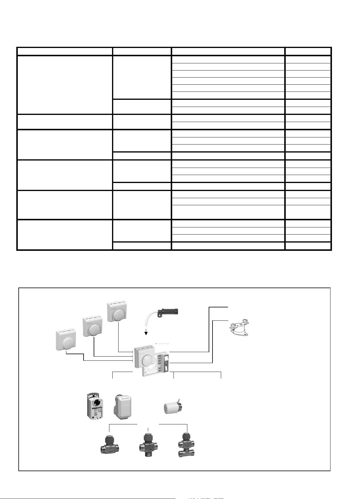
SYSTEM ARCHITECTURE
A diagram of compatible T8078B system components is shown below.
Q979C1036
Q979C1036
REMOTE SETPOINT
REMOTE SETPOINT
REMOTE SETPOINT
Q979A1020
Q979A1020
SPACE TEMP
SPACE TEMP
SENSOR
SENSOR
REMOTE SETPOINT
Q979B1029
Q979B1029
ADJUST UNIT
ADJUST UNIT
ML6161
ML6161
ML6174
ML6174
N2024
N2024
N3424
N3424
+ SENSOR
+ SENSOR
T8109C1002
T8109C1002
T8109C1002
SENSOR
SENSOR
SENSOR
T8078C CONTROLLER
T8078C CONTROLLER
MODULATING THERMAL ON/OFF
MODULATING THERMAL ON/OFF
ACTU ATORs ACTUATOR ACTU ATOR
ACTU ATORs ACTUATOR ACTU ATOR
M7410C
M7410C
M6410C
M6410C
Q6360A1025 SUB-BASE
Q6360A1025 SUB-BASE
VALVES
VALVES
M100
M100
Z100
Z100
M8450
M8450
ENERGY SAVINGS INPUT
ENERGY SAVINGS INPUT
HEAT/COOL CHANGEOVER
HEAT/COOL CHANGEOVER
S4390A1004
S4390A1004
PIPE STAT
PIPE STAT
V5822C
V5822C
V5822C
V5832C
V5832C
V5832C
V5823A
V5823A
V5823A
V5833A
V5833A
V5833A
V5823C
V5823C
V5823C
V5833C
V5833C
V5833C
4 EN0R8535 R1 2003
Page 5
OPERATION
g
gy
gy
y
Control Modes
T8078Cgives a choice of 3 different output control modes, to
suit a range of different actuators and system requirements.
Modulating Control
3-position modulating control is a control form that exactly
positions the control valve in order to satisfy the cooling or
heating demand.
For each valve actuator there are 2 control outputs, one to
drive the valve open, and another to drive the valve closed.
The controller can send out control pulses to each of these
outputs to move the valve to any position between fully
closed and 100% open. The required valve position is
calculated using a P+I algorithm, with an adjustable
Proportional Band (Xp), and valve actuator run-time of
150seconds.
This type of control gives optimum performance over a wide
range of conditions.
On/Off Control (with P+I input)
The on/off control form used by T8078C is one where the
output is cycled on and off with a fixed cycled period. The
on-time is adjusted by a P+I algorithm so the heating or
cooling demand is met and the space is controlled to
setpoint.
The cycle rate is 6cycles/hour for cooling and heating.
For the primary control stage, the Proportional Band (Xp) can
be selected to be either 1, 2, or 4K, depending on the
system.
For the secondary control stages, the Proportional Band is
fixed at 1K and the cycle rate is 6cycles/hour for cooling,
12cycles/hour for heating.
This type of on/off control ensures closer control to setpoint
than conventional on/off control based on a temperature
differential.
TPM Control (for Thermo-Electric Actuators)
Thermo-electric (or thermal) actuators are very cost effective
devices, but they present particular difficulties to control
because of the time-lags in their response to control inputs.
Therefore T8078C uses a special Thermal Predictive
Modulating (TPM) control to operate thermal actuators in the
optimum way.
This type of on/off control ensures closer control
performance when using thermal actuators than
conventional on/off control or pulse-width modulating control.
Operating Modes
T8078C has 2 main operating modes,
Energy Savings Mode
Commissioning Mode
, and also has a
which is entered immediately on
power-up.
Comfort Mode
This is the normal operating mode, where T8078C controls
to the setpoint selected by the user.
Comfort Mode
Startup /
and
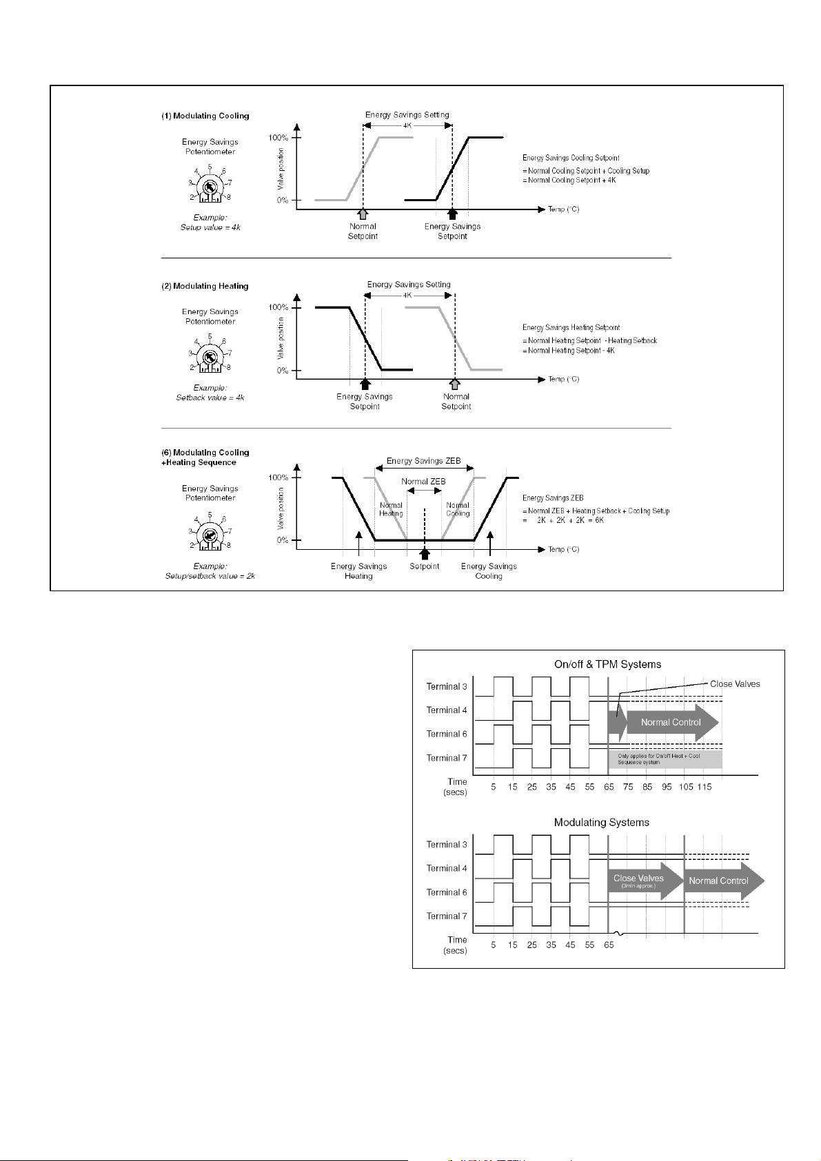
Energy Savings Mode – continued
In Energy Savings Mode the Setup/Setback values can be
set between 2-8K by means of an on-board potentiometer.
In cooling only systems (1, 7, 13) the setpoint will be
increased (setup) by the set value fixed by the potentiometer.
In heating only systems (2, 8, 14) the setpoint will be
decreased (setback).
In heat/cool changeover systems (5, 11, 17) the heating
setpoint will be decreased in heating mode, and the cooling
setpoint will be increased in cooling mode.
In coolin
+ heatingsystems (anysystem with a Zero Ener
Band) the cooling setpoint will be increased by the set value
and the heating setpoint will be decreased by the same
amount. The setpoint remains the same, but the effect is to
widen the Zero Ener
Band.
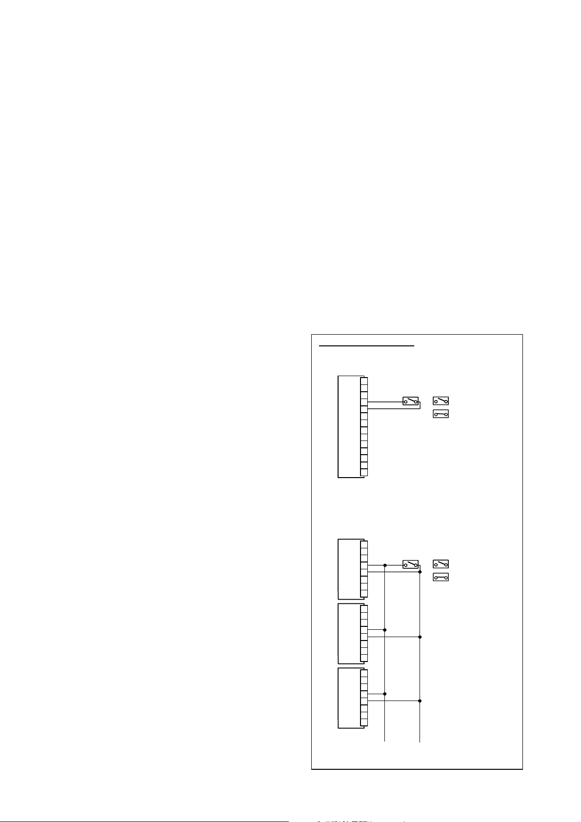
Energy Savings - From Central Location
A group of T8078C units can be switched to Energy Savings
mode using a central switch. A maximum of 50 units can be
switched this wa
the polarity of wiring connections is correct.
Each T8078C controller will switch to its own pre-defined
setback values, as set by its on-board potentiometer.
Input Wiring Connections
Input Wiring Connections
Single Unit Energy Savings
Single Unit Energy Savings
T8078C
T8078C
Central Energy Savings
Central Energy Savings
T8078C
T8078C
T8078C
T8078C
T8078C
T8078C
, but extreme care must be taken to ensure
14
14
Switch should be rated 30 Vdc
Switch should be rated 30 Vdc
13
13
0.5 mA nominal
0.5 mA nominal
12
12
11
11
10
10
9
9
8
8
7
7
6
6
5
5
4
4
3
3
2
2
1
1
Switch should be rated 30 Vdc
Switch should be rated 30 Vdc
0.5 mA nominal
0.5 mA nominal
11
11
10
10
11
11
10
10
= Normal Operation
= Normal Operation
= Energy Savings Mode
= Energy Savings Mode
= Normal Operation
= Normal Operation
= Energy Savings Mode
= Energy Savings Mode
Energy Savings Mode
T8078C has an Energy Management System, where the
detection of an external input signal will cause the cooling
and heating setpoints to change to pre-defined setup and
setback temperatures, enabling maximum energy efficiency.
This input signal must be in the form of a contact closure,
connected to terminals 10 and 11.
11
11
10
10
x 50 units maximum
x 50 units maximum
Take care to always observe polarity of connection
Take care to always observe polarity of connection
5 EN0R8535 R1 2003
Page 6
Energy Savings Mode - Examples
Startup & Commissioning
On power up, T8078C will immediately undergo a test and
synchronisation sequence to enable Installers and
Commissioning Engineers to test the system is wired correctly.
Test Sequence
For all control modes, the test sequence will last 60 seconds,
and will consist of switching the 4 control outputs on and off in
the sequence illustrated. The outputs are connected to
terminals 3, 4, 6, and 7.
If it is necessary to repeat the sequence, the power supply can
be switched off then back on again.
Valve Synchronisation
The synchronisation sequence will depend on what type of
Control Mode
For modulating systems, the test sequence will be followed by
a 3 minute valve synchronisation, where the valves will be
driven to the closed position in order to establish a baseline
control reference.
For on/off and TPM control systems, the valve closure
sequence will last 10 seconds.
The synchronisation sequence will be repeated 12 hours after
power up, and thereafter every 24 hours. This is designed to
ensure there will be no disturbance to temperature control
during normal hours of building occupancy.
The Diagnostic LED will pulse on and off in the sequence
illustrated for Terminal 3 if no faults are detected (see Section
entitled ‘Diagnostics & Fault Indication’ for a complete
description).
has been selected.
6 EN0R8535 R1 2003
Page 7

Diagnostics & Fault Indication
y
y
T8078C provides simple user diagnostics and fault
indication using an LED, positioned at the bottom right side
of the printed wiring board. The T8078C cover must be
removed to view the LED correctly.
By pulsing the LED on and off in predefined sequences,
T8078C is able to indicate valve position, heating or cooling
demand, or whether a fault has been detected.
The tables and graphs opposite give details of the how to
interpret the LED outputs.
Fault Indication
If a fault is detected, this will be indicated as highest priority.
Faults are indicated by 1, 2, or 3 LED pulses, followed b
second delay, then a repeat of the pulse sequence.
Most detectable faults are due to errors in reading sensor or
setpoint values. In the unlikel
event of an internal sensor or
unit setpoint fault, the controller must be replaced. If a
remote sensor fault is indicated, it is likely to be a bad
connection, so all wiring connections should be checked.
Valve Position / Cooling or Heating Demand
Valve position or cooling/heating demands are indicated by
an initial code sequence of pulses, followed by the position
or demand data, and this is repeated on a fixed cycle rate.
The duration of the data pulse provides the important
information, for example :
Valve position
The LED is switched on for a duration proportional to the
valve position, where 10s on = valve fully open
On/off or TPM demand
The LED is switched on for an amount proportional to the
on-period of the cycle, where 10s on = 100% demand.
T8078C will only provide demand or position data on the
current operating output, and this will be indicated by the
initial pulse sequence of 1, 2, or 3 pulses.
The table below shows how to determine current operating
mode & demand for each of the 18 possible control options.
a6
Suggested ActionFault
Suggested ActionFault
Replace controllerInternal Sensor out of range
Replace controllerInternal Sensor out of range
Check sensor connectionsRemote Sensor out of range
Check sensor connectionsRemote Sensor out of range
Replace controllerFaulty setpoint measurement
Replace controllerFaulty setpoint measurement
7 EN0R8535 R1 2003
Page 8

ORDERING INFORMATION
T8078C1009 : Controller
Accessory Products
Q979A1020
Q979B1029
Q979C1036
T8109C1002
S4390A1004
Q6360A1025
F42007789-001
F42006646-001
: Wall-mounted Remote Sensor
: Remote Setpoint Adjustment Unit (±5K)
: Remote Sensor + Setpoint Adjust Unit
: Remote Sensor (1.5m cable)
: Pipe-mounted Changeover Thermostat
: Fan Speed Switching Sub-base
: Wall-plate
: Range-stops
SYSTEM&PARAMETER SELECTION SWITCHES
T8078C uses a bank of 6 switches to enable configuration of the Control MODE,
the Applications SYSTEM, and appropriate Control Parameters, such as
PROPORTIONAL BAND (Xp) and ZERO ENERGY BAND (ZEB).
These switches are located on the wiring board underneath the cover, on the
bottom left hand side.
See the diagram below for an explanation of the switch settings.
How to Configure T8078C
(1) Select Control Type, using switches S1 and S2
The choices are :
TPM (optimised for thermal actuator control)
On/off
Modulating (3-position control) – sometimes also known as ‘Floating’ control.
(2) Select System Type, using switches S3 and S4
The choices are :
1-stage cooling (+ optional 2-stage on/off heating)
1-stage heating (+ optional 2-stage on/off cooling)
1-stage heat/cool changeover (activated by external input signal)
heat + cool sequence control
(3) Select Control Parameters, using switches S5 and S6
Proportional Band X
Zero Energy Band ZEB = 2K or 4K
= 1K, 2K or 4K (also dependant on system type)
p
8 EN0R8535 R1 2003
Page 9

INSTALLATION
j
Location
T8078C may be located on the wall in the space to be
controlled, or on the body of the terminal unit.
With In-built Temperature Sensor
T8078C is supplied with a built-in temperature sensor. If this
is to be used, then T8078C is the critical temperature control
element in the air-conditioning system, and must be located
about 1.5m above the floor in a position with good air
circulation at room temperature.
With Remote Temperature Sensor
T8078C supports remote temperature sensingfrom a rangeof
remote sensors or modules. In this case it is the position of
the sensor that is critical :
• for return air sensing the remote sensor must be
positioned within the terminal unit, duct, or plenum, in the
return air stream where it is not affected by other
influences
• for room temperature sensing the remote sensor or
module must be located as for a T8078C with in-built
sensor.
Please note :
1. The maximum cable run between T8078C and remote
sensor is 20m, and screened cable must be used.
2. T8078C uses it’s in-built sensor, unless it automatically
detects the presence of the remote sensor at power-up.
So the T8078C must be powered down then back up
again after a remote sensor is connected.
Mounting T8078C
T8078C can mounted directly on the wall or on a suitable
unction box of dimension 65 x 65mm maximum. Mounting
screws are supplied (2 x 25mm No. 6 woodscrews, 2 x 25mm
M3.5 screws) and there are 4 mounting hole locations on the
controller that can be used.
IMPORTANT !
The Installer must be a trained service engineer.
Isolate the power supply before commencing installation.
(3) Make the required wiring connections
(4) Re-attach the cover and tighten the locking screw to
complete the installation.
Wiring
The standard wiring access is through a hole at the top and
back of T8078B, but there are 4 wiring breakouts in the
cover to allow surface wiring, if necessary.
T8078C has 14 wiring terminals – all are suitable for the
connection of up to 1.5mm
Take care not to over-tighten the terminal screws during
installation, as this can damage the joints.
Refer to
schematics.
Applications
2
stranded cable.
pages for details of all wiring
Mounting on Q6360A1025 Fan Speed Sub-base
Where 230Vac fan-speed switching is required, T8078C can
be mounted on the Q6360A1025 switching sub-base, using
the screws supplied with Q6360.
All line voltage wiring connections should be made to the
sub-base before the controller is installed or wired. Line
voltage sub-base wiring and low voltage controller wiring
should be clearly separated and must comply with all
relevant local electrical codes.
Layout & Wiring Connections
(1) Unscrew the cover locking screw and remove the cover.
(2) Mount T8078C to the surface using the mounting screws
provided. If it is to be mounted onto a terminal unit, the
installer should use appropriate bolts or self-tapping screws.
Terminals
1. 24 volt supply
2. 24 volt supply (0v)
3. Valve 1 open
4. Valve 1 close
5. Valve common
6. Valve 2 open / stage 1 on/off control (applications
3,4,9,10,15,16)
7. Valve 2 close / stage 2 on/off control (applications
3,4,9,10,15,16)
8. Heat / Cool changeover input
9. Heat / Cool changeover input
10. Energy savings input
11. Energy savings input
12. Remote sensor input
13. Remote common (for remote sensor / setpoint inputs)
14. Remote setpoint input
9 EN0R8535 R1 2003
Page 10

APPLICATIONS – MODULATING CONTROL
(1) MODULATING COOLING
Valve position
Valve position
100%
100%
0%
0%
X
X
pC
pC
Setpoint
Setpoint
(oC)
(oC)
Applications
•2-pipefcuvalvecontrol
• terminal unit damper control
• 2-pipe fcu airside control
• 4-pipe fcu airside control
Notes
1) Proportional Band XpC=2K or 4K.
2) Use 4K Prop Band for 4-pipe airside control, and wire damper
motor as for actuator shown.
Wiring Schematics
2-port valves
T8078C
T8078C
14
14
13
13
12
12
11
11
10
10
9
9
8
8
7
7
6
COOL
COOL
COM
COM
6
5
5
4
4
-
-
+
+
3
3
2
2
1
1
M7410C
M7410C
BROWN
BROWN
BROWN
3-port valves
T8078C
T8078C
14
14
13
13
12
12
11
11
10
10
9
9
8
8
7
7
6
COOL
COOL
COM
COM
6
5
5
4
4
-
-
+
+
3
3
2
2
1
1
M7410C
M7410C
BROWN
BROWN
BROWN
WHITE
WHITE
WHITE
GREEN
GREEN
GREEN
WHITE
WHITE
WHITE
GREEN
GREEN
GREEN
T8109C SENS OR (OPTIONAL)
T8109C SENS OR (OPTIONAL)
V5822A
V5822A
V5832A
V5832A
M
M
M
24Vac
24Vac24Vac
~
~
T8109C SENS OR (OPTIONAL)
T8109C SENS OR (OPTIONAL)
V5823A,C
V5823A,C
V5833A,C
V5833A,C
M
M
M
24Vac
24Vac24Vac
~
~
(2) MODULATING HEATING
Valve position
Valve position
100%
100%
0%
0%
X
X
pH
pH
Setpoint
Setpoint
(oC)
(oC)
Applications
•2-pipefcuvalvecontrol
• terminal unit damper control
• 2-pipe fcu airside control
• 4-pipe fcu airside control
Notes
1) Proportional Band XpH=2K or 4K.
2) Use 4K Prop Band for 4-pipe airside control, and wire damper
motor as for actuator shown.
Wiring Schematics
2-port valves
T8078C
T8078C
14
14
13
13
12
12
11
11
10
10
9
9
8
8
7
7
6
6
COM
COM
5
5
4
4
-
HEAT
HEAT
-
+
+
3
3
2
2
1
1
BROWN
BROWN
BROWN
GREEN
GREEN
GREEN
3-port valves
T8078C
T8078C
14
14
13
13
12
12
11
11
10
10
9
9
8
8
7
7
6
6
COM
COM
5
5
4
4
-
HEAT
HEAT
-
+
+
3
3
2
2
1
1
GREEN
GREEN
GREEN
BROWN
BROWN
BROWN
M7410C
M7410C
WHITE
WHITE
WHITE
M7410C
M7410C
WHITE
WHITE
WHITE
T8109C SENSOR (OPTIONAL)
T8109C SENSOR (OPTIONAL)
V5822A
V5822A
V5832A
V5832A
M
M
M
24Vac
24Vac24Vac
~
~
T8109C SENSOR (OPTIONAL)
T8109C SENSOR (OPTIONAL)
V5823A,C
V5823A,C
V5833A,C
V5833A,C
M
M
M
24Vac
24Vac24Vac
~
~
10 EN0R8535 R1 2003
Page 11

APPLICATIONS – MODULATING CONTROL
(3) MODULATING COOLING + 2-STAGE ON/OFF HEATING Wiring Schematics
Valve position
Valve position
H
H
100%
100%
0%
0%
2
2
ID
ID
H
H
H
H
1
1
ZEB
ZEB
X
X
pC
pC
Setpoint
Setpoint
(oC)
(oC)
Applications
• 2-pipe fcu valve control with 1or 2 stage electric heat
• 2-pipe fcu airside control with 1or 2 stage electric heat
Notes
1) Proportional Band XpC=2K or 4K.
2) Zero Energy Band ZEB=2K or 4K.
3) Valve must be closed before heating comes on.
4) Heating stages H
5) H
1&H2
=1K (fixed).
are P+I on/off control with 1K prop. Band.
1&H2
6) Heating stages cycle rate=12c/hour (fixed).
7) Interstage Differential ID
8) Stages H
do not switch together -20s delay.
1&H2
=1K (fixed).
H
9) For airside control, wire damper motor as for actuator shown.
2-port valves
T8078C
T8078C
14
14
13
13
12
12
11
11
10
10
9
9
8
8
H
H
7
7
2
2
HEAT
HEAT
H
H
1
1
6
6
COM
COM
5
5
4
4
-
-
COOL
COOL
3
3
+
+
2
2
1
1
3-port valves
T8078C
T8078C
14
14
13
13
12
12
11
11
10
10
9
9
8
8
H
H
7
7
2
2
HEAT
HEAT
H
H
1
1
6
6
COM
COM
5
5
4
4
-
-
COOL
COOL
3
3
+
+
2
2
1
1
ELECTRIC HEAT (STAGE H
ELECTRIC HEAT (STAGE H
ELECTRIC HEAT (STAGE H1)
ELECTRIC HEAT (STAGE H1)
M7410C
M7410C
WHITE
WHITE
WHITE
BROWN
BROWN
BROWN
M
M
M
GREEN
GREEN
GREEN
ELECTRIC HEAT (STAGE H
ELECTRIC HEAT (STAGE H
ELECTRIC HEAT (STA GE H1)
ELECTRIC HEAT (STA GE H1)
M7410C
M7410C
WHITE
WHITE
WHITE
GREEN
GREEN
GREEN
M
M
M
BROWN
BROWN
BROWN
T8109C SENSOR (OPTIONAL)
T8109C SENSOR (OPTIONAL)
)
)
2
2
V5822A
V5822A
V5832A
V5832A
24Vac
24Vac
~
~
T8109C SENSOR (OPTIONAL)
T8109C SENSOR (OPTIONAL)
)
)
2
2
V5823A,C
V5823A,C
V5833A,C
V5833A,C
24Vac
24Vac
~
~
(4) MODULATING HEATING + 2-STAGE ON/OFF COOLING
Valve position
Valve position
100%
100%
0%
0%
X
X
pH
pH
Setpoint
Setpoint
ZEB
ZEB
C
C
2
2
ID
ID
C
C
C
C
1
1
(oC)
(oC)
Applications
• 2-pipe fcu valve control with 1 or 2 stage chiller
• 2-pipe fcu airside control with 1 or 2 stage chiller
Notes
1) Proportional Band XpH=2K or 4K.
2) Zero Energy Band ZEB=2K or 4K.
3) Valve must be closed before cooling comes on.
4) Cooling stages C
5) C
1&C2
=1K (fixed).
are P+I on/off control with 1K prop. Band.
1&C2
6) Cooling stages cycle rate=6c/hour (fixed).
7) Interstage Differential ID
8) Stages C
do not switch together -20s delay.
1&C2
=1K (fixed).
C
9) For airside control, wire damper motor as for actuator shown.
Wiring Schematics
2-port valves
T8078C
T8078C
14
14
13
13
12
12
11
11
10
10
9
9
8
8
C
C
7
7
2
2
COOL
COOL
C
C
1
1
6
6
COM
COM
5
5
4
4
-
HEAT
HEAT
-
+
+
3
3
2
2
1
1
BROWN
BROWN
BROWN
GREEN
GREEN
GREEN
3-port valves
T8078C
T8078C
14
14
13
13
12
12
11
11
10
10
9
9
8
8
C
C
7
7
2
2
COOL
COOL
C
C
1
1
6
6
COM
COM
5
5
4
4
-
-
HEAT
HEAT
+
+
3
3
2
2
1
1
BROWN
BROWN
BROWN
M7410C
M7410C
WHITE
WHITE
WHITE
M7410C
M7410C
WHITE
WHITE
WHITE
GREEN
GREEN
GREEN
T8109C SENSOR (OPTIONAL)
T8109C SENSOR (OPTIONAL)
COOLING (STAGE C
COOLING (STAGE C
COOLING (STAGE C1)
COOLING (STAGE C1)
V5822A
V5822A
V5832A
V5832A
M
M
M
~
~
T8109C SENSOR (OPTIONAL)
T8109C SENSOR (OPTIONAL)
COOLING (STAGE C
COOLING (STAGE C
COOLING (STAGE C1)
COOLING (STAGE C1)
V5823A,C
V5823A,C
V5833A,C
V5833A,C
M
M
M
~
~
24Vac
24Vac
24Vac
24Vac
2
2
)
)
)
)
2
2
11 EN0R8535 R1 2003
Page 12

APPLICATIONS – MODULATING CONTROL
(5) MODULATING HEAT / COOL CHANGEOVER Wiring Schematics
Valve position
Valve position
100%
100%
0%
0%
Heating
Heating
Mode
Mode
X
X
pCH
pCH
Setpoint
Setpoint
Cooling
Cooling
Mode
Mode
(oC)
(oC)
Applications
• 2-pipe fcu valve control with input signal for automatic changeover
Notes
1) Proportional Band X
=2K or 4K.
pCH
2) Wire as for Cooling control.
3) External input signal changes operating mode from cooling to heating.
4) Contact closure signal from single aquastat.
5) Contact closure signal from central control switch – ensure correct
polarity of connection to all T8078C units.
2-port valves
T8078C
T8078C
14
14
13
13
12
12
11
11
10
10
9
9
8
8
7
7
6
6
COM
COM
5
5
4
4
-
-
COOL
COOL
3
3
+
+
2
2
1
1
3-port valves
T8078C
T8078C
14
14
13
13
12
12
11
11
10
10
9
9
8
8
7
7
6
6
COM
COM
5
5
4
4
-
-
COOL
COOL
3
3
+
+
2
2
1
1
M7410C
M7410C
WHITE
WHITE
WHITE
BROWN
BROWN
BROWN
GREEN
GREEN
GREEN
M7410C
M7410C
WHITE
WHITE
WHITE
GREEN
GREEN
GREEN
BROWN
BROWN
BROWN
T8109C SENSOR (OPTIONAL)
T8109C SENSOR (OPTIONAL)
S4390A
S4390A
HEAT / COOL
HEAT / COOL
CHANGEOVER SWITCH
CHANGEOVER SWITCH
V5822A
V5822A
V5832A
V5832A
M
M
M
24Vac
24Vac24Vac
T8109C SENSOR (OPTIONAL)
T8109C SENSOR (OPTIONAL)
S4390A
S4390A
HEAT / COOL
HEAT / COOL
CHANGEOVER SWITCH
CHANGEOVER SWITCH
V5823A,C
V5823A,C
V5833A,C
V5833A,C
M
M
M
24Vac
24Vac24Vac
(6) MODULATING COOLING + HEATING SEQUENCE
Valve position
Valve position
100%
100%
0%
0%
X
X
pH
pH
ZEB
ZEB
Setpoint
Setpoint
X
X
pC
pC
(oC)
(oC)
Applications
•4-pipefcuvalvecontrol
Notes
1) Both Proportional Bands XpC&XpH=1K or 2K.
2) Zero Energy Band ZEB=2K or 4K.
3) Heat valve is closed before cooling valve opens.
4) Cool valve is closed before heating valve opens.
Wiring Schematics
2-port valves
T8078C
T8078C
14
14
13
13
12
12
11
11
10
10
9
9
8
HEAT
HEAT
COOL
COOL
COM
COM
8
7
7
-
-
+
+
6
6
5
5
4
4
-
-
3
3
+
+
2
2
1
1
BROWN
BROWN
BROWN
BROWN
BROWN
BROWN
3-port valves
T8078C
T8078C
14
14
13
13
12
12
11
11
10
10
9
9
8
8
7
7
-
-
HEAT
HEAT
COOL
COOL
COM
COM
+
+
6
6
5
5
4
4
-
-
3
3
+
+
2
2
1
1
BROWN
BROWN
BROWN
BROWN
M7410C
M7410C
GREEN
GREEN
GREEN
WHITE
WHITE
WHITE
WHITE
WHITE
WHITE
GREEN
GREEN
GREEN
M7410C
M7410C
GREEN
GREEN
WHITE
WHITE
WHITE
WHITE
GREEN
GREEN
T8109C SENS OR (OPTIONAL)
T8109C SENS OR (OPTIONAL)
V5822A
V5822A
V5832A
V5832A
M
M
M
M
M
M
24Vac
24Vac24Vac
~
~
T8109C SENS OR (OPTIONAL)
T8109C SENS OR (OPTIONAL)
V5823A,C
V5823A,C
V5833A,C
V5833A,C
M
M
M
M
24Vac
24Vac
~
~
12 EN0R8535 R1 2003
Page 13

APPLICATIONS – ON / OFF CONTROL
(7) ON/OFF COOLING Wiring Schematics
Valve position
Valve position
100%
100%
100%
0%
0%
0%
X
X
X
pC
pC
pC
Setpoint
Setpoint
Setpoint
(oC)
(oC)
(oC)
Applications
•2-pipefcuvalvecontrol
Notes
1) Control is P+I on/off.
2) Cycle rate is 6c/hour (fixed).
3) Proportional Band X
=2K or 4K.
pC
4) Can use valves that require only to be driven in one direction (for
example, with thermal actuators) or valves that require to be driven
open, then driven closed.
5) Normally closed valves: use output from (+) terminal to drive open.
6) Normally open valves: use output from (-) terminal to drive closed.
Drive open valves
T8078C
T8078C
14
14
13
13
12
12
11
11
10
10
9
9
8
8
7
7
6
6
COM
COM
5
5
4
4
-
-
COOL
COOL
+
+
3
3
2
2
1
1
Drive open / drive closed valves
T8078C
T8078C
14
14
13
13
12
12
11
11
10
10
9
9
8
8
7
7
6
6
COM
COM
5
5
4
4
-
-
COOL
COOL
+
+
3
3
2
2
1
1
ACTUATOR
ACTUATOR
COMMON
COMMON
OPEN VALVE
OPEN VALVE
ACTUATOR
ACTUATOR
COMMON
COMMON
CLOSE
CLOSE
OPEN
OPEN
T8109C SENSOR (OPTIONAL)
T8109C SENSOR (OPTIONAL)
24Vac
24Vac24Vac
~
T8109C SENS OR (OPTIONAL)
T8109C SENS OR (OPTIONAL)
24Vac
24Vac24Vac
~
(8) ON/OFF HEATING
Valve position
Valve position
Valve position
100%
100%
100%
0%
0%
0%
X
X
X
pH
pH
pH
Setpoint
Setpoint
Setpoint
(oC)
(oC)
Applications
•2-pipefcuvalvecontrol
Notes
1) Control is P+I on/off.
2) Cycle rate is 6c/hour (fixed).
3) Proportional Band X
=2K or 4K.
pH
4) Can use valves that require only to be driven in one direction (for
example, with thermal actuators) or valves that require to be driven
open, then driven closed.
5) Normally closed valves: use output from (+) terminal to drive open.
6) Normally open valves: use output from (-) terminal to drive closed.
Wiring Schematics
Drive open valves
T8078C
T8078C
14
14
13
HEAT
HEAT
COM
COM
13
12
12
11
11
10
10
9
9
8
8
7
7
6
6
5
5
4
4
-
-
+
+
3
3
2
2
1
1
ACTUATOR
ACTUATOR
COMMON
COMMON
T8109C SENSOR (OPTIONAL)
T8109C SENSOR (OPTIONAL)
OPEN
OPEN
~
~
24Vac
24Vac24Vac
Drive open / drive closed valves
T8078C
T8078C
14
14
13
HEAT
HEAT
COM
COM
13
12
12
11
11
10
10
9
9
8
8
7
7
6
6
5
5
4
4
-
-
+
+
3
3
2
2
1
1
ACTUATOR
ACTUATOR
COMMON
COMMON
CLOSE
CLOSE
T8109C SENSOR (OPTIONAL)
T8109C SENSOR (OPTIONAL)
OPEN
OPEN
~
~
24Vac
24Vac24Vac
13 EN0R8535 R1 2003
Page 14

APPLICATIONS – ON / OFF CONTROL
(9) ON/OFF COOLING + 2-STAGE ON/OFF HEATING Wiring Schematics
Valve position
Valve position
H
H
100%
100%
0%
0%
2
2
ID
ID
H
H
H
H
1
1
ZEB
ZEB
X
X
pC
pC
Setpoint
Setpoint
(oC)
(oC)
Applications
• 2-pipe fcu valve control with 1or 2 stage electric heat
Notes
1) Cooling control is P+I form, with 6c/hour cycle rate.
2) Cooling Proportional Band X
=2K or 4K.
pC
3) Zero Energy Band ZEB=2K or 4K.
4) Cooling valve must be closed before heating comes on.
5) Heating stages H
6) H
1&H2
=1K (fixed).
are P+I on/off control with 1K Prop. Band.
1&H2
7) Heating stages cycle rate=12c/hour (fixed).
8) Interstage Differential ID
9) Stages H
do not switch together -20s delay.
1&H2
=1K (fixed).
H
Drive open valves
T8078C
T8078C
14
14
13
13
12
12
11
11
10
10
9
9
8
8
H
H
7
7
2
2
HEAT
HEAT
H
H
1
1
6
6
COM
COM
5
5
4
4
-
-
COOL
COOL
3
3
+
+
2
2
1
1
Drive open / drive closed valves
T8078C
T8078C
14
14
13
13
12
12
11
11
10
10
9
9
8
8
H
H
7
7
2
2
HEAT
HEAT
H
H
1
1
6
6
COM
COM
5
5
4
4
-
-
COOL
COOL
3
3
+
+
2
2
1
1
T8109C SENSOR (OPTIONAL)
T8109C SENSOR (OPTIONAL)
ELECTRIC HEAT (STAGE H
ELECTRIC HEAT (STAGE H
ELECTRIC HEAT (STAGE H1)
ELECTRIC HEAT (STAGE H1)
ACTUATOR
ACTUATOR
COMMON
COMMON
OPEN VALVE
OPEN VALVE
~
~
T8109C SENSOR (OPTIONAL)
T8109C SENSOR (OPTIONAL)
ELECTRIC HEAT (STAGE H
ELECTRIC HEAT (STAGE H
ELECTRIC HEAT (STAGE H1)
ELECTRIC HEAT (STAGE H1)
COMMON
COMMON
CLOSEVALVE
CLOSEVALVE
OPEN VALVE
OPEN VALVE
ACTUATOR
ACTUATOR
~
~
24Vac
24Vac
24Vac
24Vac
)
)
2
2
)
)
2
2
(10) ON/OFF HEATING + 2-STAGE ON/OFF COOLING
Valve position
Valve position
100%
100%
0%
0%
X
X
pH
pH
Setpoint
Setpoint
ZEB
ZEB
C
C
2
2
ID
ID
C
C
C
C
1
1
(oC)
(oC)
Applications
• 2-pipe fcu valve control with 1 or 2 stage chiller
Notes
1) Heating control is P+I form, with 6c/hour cycle rate.
2) Heating Proportional Band X
=2K or 4K.
pH
3) Zero Energy Band ZEB=2K or 4K.
4) Heating valve must be closed before cooling comes on.
5) Cooling stages C
6) C
1&C2
=1K (fixed).
are P+I on/off control with 1K Prop. Band.
1&C2
7) Cooling stages cycle rate=6c/hour (fixed).
8) Interstage Differential ID
9) Stages C
do not switch together -20s delay.
1&C2
=1K (fixed).
C
Wiring Schematics
Drive open valves
T8078C
T8078C
14
14
13
COOL
COOL
HEAT
HEAT
COM
COM
13
12
12
11
11
10
10
9
9
8
8
C
C
7
7
2
2
C
C
1
1
6
6
5
5
4
4
-
-
+
+
3
3
2
2
1
1
COMMON
COMMON
OPEN VALVE
OPEN VALVE
T8109C SENSOR (OPTIONAL)
T8109C SENSOR (OPTIONAL)
COOLING (STAGE C
COOLING (STAGE C
COOLING (STAGE C1)
COOLING (STAGE C1)
ACTUATOR
ACTUATOR
~
~
24Vac
24Vac
Drive open / drive closed valves
T8078C
T8078C
14
14
13
COOL
COOL
HEAT
HEAT
COM
COM
13
12
12
11
11
10
10
9
9
8
8
H
H
7
7
2
2
H
H
1
1
6
6
5
5
4
4
-
-
3
3
+
+
2
2
1
1
CLOSEVALVE
CLOSEVALVE
OPEN VALVE
OPEN VALVE
T8109C SENSOR (OPTIONAL)
T8109C SENSOR (OPTIONAL)
COOLING (STAGE H
COOLING (STAGE H
COOLING (STAGE H1)
COOLING (STAGE H1)
COMMON
COMMON
ACTUATOR
ACTUATOR
~
~
24Vac
24Vac
)
)
2
2
)
)
2
2
14 EN0R8535 R1 2003
Page 15

APPLICATIONS – ON / OFF CONTROL
(11) ON/OFF HEAT / COOL CHANGEOVER Wiring Schematics
Valve position
Valve position
100%
100%
0%
0%
Heating
Heating
Mode
Mode
X
X
pCH
pCH
Setpoint
Setpoint
Cooling
Cooling
Mode
Mode
(oC)
(oC)
Applications
• 2-pipe fcu valve control with input signal for automatic changeover
Notes
1) Control is P+I form, with 6c/hour cycle rate (heating or cooling).
2) Proportional Band X
=2K or 4K.
pCH
3) Wire as for Cooling control.
4) External input signal changes operating mode from cooling to heating.
5) Contact closure signal from single aquastat.
6) Contact closure signal from central control switch – ensure correct
polarity of connection to all T8078C units.
Drive open valves
T8078C
T8078C
14
14
13
13
12
12
11
11
10
10
9
9
8
8
7
7
6
6
COM
COM
5
5
4
4
-
-
COOL
COOL
3
3
+
+
2
2
1
1
Drive open / drive closed valves
T8078C
T8078C
14
14
13
13
12
12
11
11
10
10
9
9
8
8
7
7
6
6
COM
COM
5
5
4
4
-
-
COOL
COOL
3
3
+
+
2
2
1
1
ACTUATOR
ACTUATOR
COMMON
COMMON
OPEN VALVE
OPEN VALVE
ACTUATOR
ACTUATOR
COMMON
COMMON
CLOSEVALVE
CLOSEVALVE
OPEN VALVE
OPEN VALVE
T8109C SENSOR (OPTIONAL)
T8109C SENSOR (OPTIONAL)
S4390A
S4390A
HEAT / COOL
HEAT / COOL
CHANGEOVER SWITCH
CHANGEOVER SWITCH
24Vac
24Vac24Vac
~
~
T8109C SENSOR (OPTIONAL)
T8109C SENSOR (OPTIONAL)
S4390A
S4390A
HEAT / COOL
HEAT / COOL
CHANGEOVER SWITCH
CHANGEOVER SWITCH
24Vac
24Vac24Vac
~
~
(12) ON/OFF COOLING + HEATING SEQUENCE
Valve position
Valve position
100%
100%
0%
0%
X
X
pH
pH
ZEB
ZEB
Setpoint
Setpoint
X
X
pC
pC
(oC)
(oC)
Applications
•4-pipefcuvalvecontrol
Notes
1) Both stages are P+I on/off control, with 6c/hour cycle rate.
2) Both Proportional Bands X
pC&XpH
=1K or 2K.
3) Zero Energy Band ZEB=2K or 4K.
4) Heat valve is closed before cooling valve opens.
5) Cool valve is closed before heating valve opens.
Wiring Schematics
Drive open valves
T8078C
T8078C
14
14
13
HEAT
HEAT
COOL
COOL
COM
COM
13
12
12
11
11
10
10
9
9
8
8
7
7
-
-
+
+
6
6
5
5
4
4
-
-
3
3
+
+
2
2
1
1
OPEN VALVE
OPEN VALVE
COMMON
COMMON
COMMON
COMMON
OPEN VALVE
OPEN VALVE
T8109C SENSOR (OPTIONAL)
T8109C SENSOR (OPTIONAL)
HEAT
HEAT
ACTUATOR
ACTUATOR
COOL
COOL
ACTUATOR
ACTUATOR
24Vac
24Vac24Vac
~
~
Drive open / drive closed valves
T8078C
T8078C
14
14
13
HEAT
HEAT
COOL
COOL
COM
COM
13
12
12
11
11
10
10
9
9
8
8
7
7
-
-
+
+
6
6
5
5
4
4
-
-
3
3
+
+
2
2
1
1
CLOSE VALVE
CLOSE VALVE
CLOSE VALVE
OPEN VALVE
OPEN VALVE
OPEN VALVE
COMMON
COMMON
COMMON
COMMON
COMMON
CLOSEVALVE
CLOSEVALVE
OPEN VALVE
OPEN VALVE
T8109C SENSOR (OPTIONAL)
T8109C SENSOR (OPTIONAL)
HEAT
HEAT
ACTUATOR
ACTUATOR
COOL
COOL
ACTUATOR
ACTUATOR
24Vac
24Vac24Vac
~
~
15 EN0R8535 R1 2003
Page 16

APPLICATIONS – TPM CONTROL (THERMO-ELECTRIC ACTUATORS)
13) TPM COOLING Wiring Schematic
Valve position
Valve position
100%
100%
100%
0%
0%
0%
X
X
X
pC
pC
pC
Setpoint
Setpoint
Setpoint
(oC)
(oC)
(oC)
Applications
• 2-pipe fcu valve control (with thermal actuator)
Notes
1) Special algorithm for thermal actuators.
2) Proportional Band X
=2K or 4K.
pC
3) Only suitable for normally closed valves: where actuator is
powered to drive valve open.
For normally closed valve – drive to open
T8078C
T8078C
14
14
13
COOL
COOL
COM
COM
13
12
12
11
11
10
10
9
9
8
8
7
7
6
6
5
5
4
4
-
+
+
3
3
2
2
1
1
ACTUATOR
ACTUATOR
COMMON
COMMON
OPEN VALVE
OPEN VALVE
T8109C SENSOR (OPTIONAL)
T8109C SENSOR (OPTIONAL)
~
24Vac
24Vac24Vac
(14) TPM HEATING
Valve position
Valve position
Valve position
100%
100%
100%
0%
0%
0%
X
X
X
pH
pH
pH
Setpoint
Setpoint
Setpoint
(oC)
(oC)
Applications
• 2-pipe fcu valve control (with thermal actuator)
Notes
1) Special algorithm for thermal actuators.
2) Proportional Band X
=2K or 4K.
pH
3) Only suitable for normally closed valves: where actuator is
powered to drive valve open.
Wiring Schematic
For normally closed valve – drive to open
T8078C
T8078C
14
14
13
HEAT
HEAT
COM
COM
13
12
12
11
11
10
10
9
9
8
8
7
7
6
6
5
5
4
4
-
+
+
3
3
2
2
1
1
ACTUATOR
ACTUATOR
COMMON
COMMON
T8109C SENSOR (OPTIONAL)
T8109C SENSOR (OPTIONAL)
OPEN
OPEN
~
~
24Vac
24Vac24Vac
16 EN0R8535 R1 2003
Page 17

APPLICATIONS – TPM CONTROL (THERMO-ELECTRIC ACTUATORS)
(15) TPM COOLING + 2-STAGE ON/OFF HEATING Wiring Schematic
Valve position
Valve position
H
H
100%
100%
0%
0%
2
2
ID
ID
H
H
H
H
1
1
ZEB
ZEB
X
X
pC
pC
Setpoint
Setpoint
(oC)
(oC)
Applications
• 2-pipe fcu valve control with 1or 2 stage electric heat
Notes
1) Cooling control is special algorithm for thermal actuators.
2) Only suitable for normally closed valves: where actuator is
powered to drive valve open.
3) Cooling Proportional Band X
=2K or 4K.
pC
4) Zero Energy Band ZEB=2K or 4K.
5) Heating stages H
6) H
1&H2
=1K (fixed).
are P+I on/off control with 1K Prop. Band.
1&H2
7) Heating stages cycle rate=12c/hour (fixed).
8) Interstage Differential ID
9) Stages H
do not switch together -20s delay.
1&H2
=1K (fixed).
H
For normally closed valve – drive to open
T8078C
T8078C
14
14
13
13
12
12
11
11
10
HEAT
HEAT
COOL
COOL
COM
COM
10
9
9
8
8
H
H
7
7
2
2
H
H
1
1
6
6
5
5
4
4
-
-
3
3
+
+
2
2
1
1
ELECTRIC HEAT (STAGE H
ELECTRIC HEAT (STAGE H
ELECTRIC HEAT (STAGE H1)
ELECTRIC HEAT (STAGE H1)
ACTUATOR
ACTUATOR
COMMON
COMMON
OPEN VALVE
OPEN VALVE
T8109C SENSOR (OPTIONAL)
T8109C SENSOR (OPTIONAL)
)
)
2
2
24Vac
24Vac
~
~
(16) TPM HEATING + 2-STAGE ON/OFF COOLING
Valve position
Valve position
100%
100%
0%
0%
X
X
pH
pH
Setpoint
Setpoint
ZEB
ZEB
C
C
2
2
ID
ID
C
C
C
C
1
1
(oC)
(oC)
Applications
• 2-pipe fcu valve control with 1 or 2 stage chiller
Notes
1) Heating control is special algorithm for thermal actuators.
2) Only suitable for normally closed valves: where actuator is
powered to drive valve open.
3) Heating Proportional Band X
=2K or 4K.
pH
4) Zero Energy Band ZEB=2K or 4K.
5) Cooling stages C
6) C
1&C2
=1K (fixed).
are P+I on/off control with 1K Prop. Band.
1&C2
7) Cooling stages cycle rate=6c/hour (fixed).
8) Interstage Differential ID
9) Stages C
do not switch together -20s delay
1&C2
=1K (fixed).
C
Wiring Schematic
For normally closed valve – drive to open
T8078C
T8078C
14
14
13
COOL
COOL
HEAT
HEAT
COM
COM
13
12
12
11
11
10
10
9
9
8
8
C
C
7
7
2
2
C
C
1
1
6
6
5
5
4
4
-
-
+
+
3
3
2
2
1
1
COMMON
COMMON
OPEN VALVE
OPEN VALVE
T8109C SENSOR (OPTIONAL)
T8109C SENSOR (OPTIONAL)
COOLING (STAGE C
COOLING (STAGE C
COOLING (STAGE C1)
COOLING (STAGE C1)
ACTUATOR
ACTUATOR
~
~
24Vac
24Vac
)
)
2
2
17 EN0R8535 R1 2003
Page 18

APPLICATIONS – TPM CONTROL (THERMO-ELECTRIC ACTUATORS)
(17) TPM HEAT / COOL CHANGEOVER Wiring Schematic
Valve position
Valve position
100%
100%
0%
0%
Heating
Heating
Mode
Mode
X
X
pCH
pCH
Setpoint
Setpoint
Cooling
Cooling
Mode
Mode
(oC)
(oC)
Applications
• 2-pipe fcu valve control with input signal for automatic changeover
Notes
1) Control is special algorithm for thermal actuators.
2) Only suitable for normally closed valves: where actuator is powered to
drive valve open.
3) Proportional Band X
=2K or 4K.
pCH
4) Wire as for Cooling control.
5) External input signal changes operating mode from cooling to heating.
6) Contact closure signal from single aquastat.
7) Contact closure signal from central control switch – ensure correct
polarity of connection to all T8078C units.
For normally closed valve – drive to open
T8078C
T8078C
14
14
13
COOL
COOL
COM
COM
13
12
12
11
11
10
10
9
9
8
8
7
7
6
6
5
5
4
4
-
-
3
3
+
+
2
2
1
1
COMMON
COMMON
OPEN VALVE
OPEN VALVE
T8109C SENSOR (OPTIONAL)
T8109C SENSOR (OPTIONAL)
ACTUATOR
ACTUATOR
S4390A
S4390A
HEAT / COOL
HEAT / COOL
CHANGEOVER SWITCH
CHANGEOVER SWITCH
24Vac
24Vac24Vac
~
~
(18) TPM COOLING + HEATING SEQUENCE
Valve position
Valve position
100%
100%
0%
0%
X
X
pH
pH
ZEB
ZEB
Setpoint
Setpoint
X
X
pC
pC
(oC)
(oC)
Applications
•4-pipefcuvalvecontrol
Notes
1) Control is special algorithm for thermal actuators.
2) Only suitable for normally closed valves: where actuator is
powered to drive valve open.
3) Both Proportional Bands X
pC&XpH
=1K or 2K.
4) Zero Energy Band ZEB=2K or 4K.
Wiring Schematic
For normally closed valves – drive to open
T8078C
T8078C
14
14
13
HEAT
HEAT
COOL
COOL
COM
COM
13
12
12
11
11
10
10
9
9
8
8
7
7
-
-
+
+
6
6
5
5
4
4
-
-
3
3
+
+
2
2
1
1
OPEN VALVE
OPEN VALVE
COMMON
COMMON
COMMON
COMMON
OPEN VALVE
OPEN VALVE
T8109C SENSOR (OPTIONAL)
T8109C SENSOR (OPTIONAL)
HEAT
HEAT
ACTUATOR
ACTUATOR
COOL
COOL
ACTUATOR
ACTUATOR
24Vac
24Vac24Vac
~
~
18 EN0R8535 R1 2003
Page 19

ADDITIONAL FEATURES
Automatic Heat / Cool Changeover
T8078C is suitable for automatic or central Heat / Cool
Changeover, if configured for this Mode of operation. This
is applicable only for 2-pipe fan-coil systems, where the
changeover is made on a seasonal demand basis.
Configuration is done by setting System switches S3 and S4
to 1 and 0 respectively.
Automatic changeover is initiated by a thermostat positioned
on the water flow pipe, detecting the presence of heated or
chilled water, and sending the appropriate signal to the
controller. A suitable product is the S4390A1004 pipethermostat.
Central changeover is initiated by a switch, and can be used
to centrally switch a group of connected T8078C controllers
from Heating to Cooling operation.
See wiring schematics for connection details.
Remote Temperature Sensor
T8078C is supplied with an on-board temperature sensor. If
remote temperature sensing is required (for example in
return air sensing applications), then a suitable Honeywell
Remote Sensor can be connected to terminals 12 and 13 as
shown in the wiring schematic.
T8078C will auto detect the presence of the Remote Sensor
on power up, and will use the Remote Sensor measurement
in preference to its internal sensor. So if a Remote Sensor is
to be connected, the power must be switched off then on
again for it to be detected.
Remote Sensors are available as wall-mounted or airflow
(return air) models. Both Q979A1020 and Q979C1036
contain the sensor in wall-mounted form, whereas
T8109C1002 is an airflow sensor supplied with 1.5 m cable.
If this cable is to be extended then the maximum cable run
will be 20m, and the extension must use screened cable.
Polarity of connection is not important, but the screen wire
must be connected to terminal 9 or 10, as shown.
T8109C1002 Sensor
Note : x 50 units maximum
Take care to always observe polarity of connection
Q979A1020 Wall-mounted Sensor
19 EN0R8535 R1 2003
Page 20

Remote Setpoint Adjustment
y
Suitable Valves & Actuators
T8078C allows its setpoint to be adjusted remotely by up to
±5K. This is achieved by the connection of a Remote
Setpoint Adjustment module to terminals 13 and 14, as
shown in the wiring schematic.
Suitable modules are :
Q979B1029 (Remote Setpoint Adjust) and
Q979C1036 (Sensor + Remote Setpoint Adjust).
Note – the polarit
is purely resistive.
To ensure measurement stability when wiring these
modules, use screened cable and connect the screen wire to
terminal 9 or 10 of T8078C as shown.
The maximum cable run will be 20m.
of connection is not important as the input
T8078C is compatible with a range of Honeywell valves and
actuators, as shown in the table below. See relevant product
Specificaton Sheets for more details.
Valve Actuators Suitable Valves
Conical Sealing
M6410C
M7410C
Modulating 3-pos, 24V~
Max of 10 actuators
(0.7VA each) to be
connected to any
T8078C output
M8450A1000
Thermo-electric, 24V~
Stroke 8mm
Max of 2 actuators (3VA
each) to be connected to
any T8078C output
M100
Thermo-electric, 24V~
Stroke 2.5mm
Z100
Thermo-electric, 24V~
Stroke 4mm
Max of 2 actuators (3VA
each) to be connected to
any T8078C output
V5822A 2-way
V5823A 3-way
V5823C 3-way+bypass
Flat Sealing
V5832A 2-way
V5833A 3-way
V5833C 3-way+bypass
Conical Sealing
V5822A 2-way
V5823A 3-way
V5823C 3-way+bypass
Flat Sealing
V5832A 2-way
V5833A 3-way
V5833C 3-way+bypass
Conical Sealing
V5822A4xxx 2-way
V5823A4xxx 3-way
V5823C4xxx 3-way+bypass
Flat Sealing
V5832A4xxx 2-way
V5833A4xxx 3-way
V5833C4xxx 3-way+bypass
Damper Actuators
Modulating 3-pos, 24V~
4Nm
ML6161B2024
5Nm
ML6161E
10Nm
ML6174E
20Nm
N2024
34Nm
N3424
Max no. to be connected
to each T8078C output
Max of 3 actuators (2VA each)
Max of 2 actuators (4VA each)
Max of 2 actuators (4VA each)
Max of 1 actuator (6VA each)
Max of 1 actuator (7VA each)
Optional Accessories
Optional accessories are available for use with T8078C:
F42006646-001 Range stops (pack of 20)
F42007789-001 Wall-plate
Q6360A1025 Fan Speed Switching Subbase
Q979A1020 Wall mounted Remote Sensor
Q979B1029 Remote Setpoint Adjust Unit (±5K)
Q979C1036 Sensor + Remote Setpoint Unit (±5K)
T8109C1002 Return Air Sensor (1.5m cable)
S4390A1004 Pipe-mounted Changeover Thermostat
Honeywell Control Systems Limited
Newhouse Industrial Estate
Motherwell ML1 5SB
United Kingdom
Honeywell
http://europe.hbc.honeywell.com
20 EN0R8535 R1 2003
 Loading...