

Page 1
T8001F, T8024F Flush Mount
Programmable Thermostat
INSTALLATION INSTRUCTIONS
APPLICATION
The T8001F Thermostat provides single-stage,
programmable temperature control for 24 Vac heatingcooling systems with manual changeover from heat to
cool. The T8024F Thermostat provides multistage
electronic control of single-zone heating and c ooling
systems. Heating cycle rate is selectable at 1, 3, 4, 5, 6,
9, or 12 cph. Cooling cycle rate is fixed at 3 cph.
Temperature indication can be set for °F or °C.
The T8001F, T8024F Thermostat is powered directly
from the system transformer. Batteries are not required
because setpoints are held permanently by non-volatile
memory.
The T8001F, T8024F model includes a thermostat,
wallplate and owner’s guide. See Table 1.
MERCURY NOTICE
If this control is replacing a control that contains
mercury in a sealed tube, do not place your old
control in the trash. Dispose of it properly.
Contact your local waste management authority
for instructions regarding recycling and the
proper disposal of the control.
INSTALLATION
When Installing this Product…
1. Read these instructions carefully. Failure to follow
them could damage the product or cause a hazardous condition.
2. Check the ratings given in the instructions and on
the product to make sure the product is suitable for
your application.
Table 1. Thermostat Descriptions.
Model System Changeover System Selection Fan Selection Powering Method
T8001F Heat-Cool Manual Cool-Off-Heat Auto-On Hardwired
T8024F Heat-Cool Manual Cool-Off-Heat Auto-On Hardwired
3. Installer must be a trained, experienced service
technician.
4. After installation is complete, check out product
operation as provided in these instructions.
CAUTION
Hazardous Voltage.
Can damage heating/cooling system.
Disconnect power at furnace or main breaker/
fuse box.
Location
Install the thermostat about 5 ft (1.5m) above the floor in
an area with good air circulation at average temperature.
See Fig. 1. Do not install the thermostat where it can be
affected by:
— drafts or dead spots behind doors and in corners.
— hot or cold air from ducts.
— radiant heat from the sun or appliances.
— concealed pipes and chimneys.
— unheated (uncooled) areas such as an outside wall
behind the thermostat.
Installing Wallplate in Wall
IMPORTANT
Level only for appearance. The thermostat functions normally even when not level.
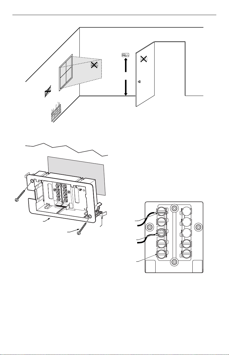
Mount wallplate and the T8001F or T8024F with the wing
anchors provided (see Fig. 2) as follows:
1. Place the wallplate template at the desired location
on the wall.
2. Trace and cutout the opening.
3. Pull the thermostat wire through the wallplate
entrance hole.
4. Fasten the wallplate to the wall using the wing
anchors.
® U.S. Registered Trademark
Copyright © 2001 Honeywell • • All Rights Reserved
69- 1465- 3
Page 2
T8001F, T8024F FLUSH MOUNT PROGRAMMABLE THERMOSTAT
2)
A
F
I
S
(
NO
WALL
WALLPLATE
MOUNTING
SCREWS (2)
Fig. 2. Mounting wallplate to wall.
Wiring
IMPORTANT
Use an 18-gauge maximum wire for wiring the
T8001F Thermostat.
YES
NO
5 FEET
[1.5 METERS]
NO
Fig. 1. Typical location of thermostat.
All wiring must comply with local electrical codes and
ordinances. Disconnect the power supply to prevent
electrical shock or equipment damage.
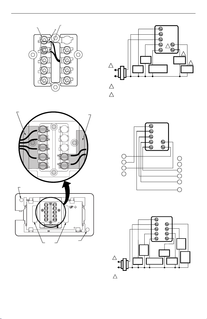
The shape of the terminals permits insertion of straight or
wraparound wiring connections; either method is
acceptable. A letter code is located near each terminal
for identification. See Fig. 3 and 4.
NOTE: To ensure correct mounting of thermostat,
restrict all wiring to shaded area in center of
terminals. See Fig. 5.
OR STRAIGHT
NSERTION
TRIP 5/16 IN.
9 MM)
WING
ANCHORS (
M18610
FOR WRAP
AROUND
STRIP 7/16 IN.
(11 MM)
TERMINAL
SCREW
Fig. 3. T8001F wiring connections.
M11338
G
C
R
W
Y
B
O
M18609
69-1465—3 2
Page 3
T8001F, T8024F FLUSH MOUNT PROGRAMMABLE THERMOSTAT
T
S
2
)
A
T8001 THERMOSTAT
1
M12567
T8001 THERMOSTAT
L
(
L
-
ERMINAL
CREW
FOR STRAIGHT
INSERTION STRIP
5/16 IN. (8 MM)
FOR WRAPAROUND
STRIP 7/16 IN. (11 MM
G
C
R
W1
Y
Fig. 4. T8024F wiring connections.
KEEP WIRING IN
SHADED AREA
G
C
R
W
Y
MOUNTING
SCREW HOLE
W2
Y2
B
O
M2021
KEEP WIRING IN
SHADED AREA
B
O
G
C
R
W
Y
HEAT
1
L1
(HOT)
L2
TRANSFORMER
1
POWER SUPPLY. PROVIDE DISCONNECT MEANS AND OVERLOAD
PROTECTION AS REQUIRED.
CAN BE USED FOR CHANGEOVER VALVE ON SINGLE-STAGE HEAT
2
PUMP SYSTEMS.
Fig. 6. Typical T8001Fhookup in heat-cool
O1
G1
B1
E1
CHANGEOVER
CONTROL
Fig. 7. Typical wiring diagram for T8001F on a zone 1
MABS II or Masterol™ control panel.
RELAY
COMPRESSOR
FAN
CONTACTOR
RELAY
system with one transformer.
G
C
R
W
Y
B
2
O
2
COOL
DAMPER
2
HEAT
DAMPER
B
O
ZONE
T8
T7
T6
T5
T4
M1
MOUNTING
SCREW HOLE
WIRING
Fig. 5. Restrict wiring to shaded area (T8001 shown).
The T8001F Thermostat is powered directly from the
system transformer and is adaptable to most 18 to
30 Vac heating-cooling systems. All T8001F Thermostats
require a common wire to supply power. Refer to Fig. 6
through 8 for typical wiring hookups.
ENTRANCE HOLE (2)
T8024 THERMOSTAT
G
C
R
W1
Y
M18608
1
1
HOT)
2
TRANSFORMER
1
POWER SUPPLY. PROVIDE DISCONNECT MEANS AND OVERLOAD
PROTECTION AS REQUIRED.
Fig. 8. Typical diagram for T8024F two-stage heat and
two-stage cool system with manual changeover.
FAN
RELAY
STAGEONE
HEAT
RELAY
STAGE ONE
COOLING
COOL
DAMPER
W2
Y2
B
O
HEAT
DAMPER
STAGETWO
COOLING
M20214
STAGE
TWO
HEAT
RELAY
3 69-1465—3
Page 4

T8001F, T8024F FLUSH MOUNT PROGRAMMABLE THERMOSTAT
M12580
FAN OPERATION (FUEL) SWITCH
1
A
3
A
A
A
Setting Fan Operation (Fuel) Switch (T8001F Only)
The fan operation (fuel) switch is preset at the factory in
the F position. See Fig. 9. This is the correct setting for
most systems. If this system is an electric heat system,
set the switch to the E position. The E setting allows the
fan to turn on immediately with the heating or cooling
equipment in a system where the G terminal is
connected.
E
F
Fig. 9. Fan operation (fuel) switch.
Mounting Thermostat to Wallplate
1. Slide SYSTEM switch to the Off position.
2. Slide the thermostat straight into the wallplate until
it is flush against the wall. See Fig. 10.
PM
TUE
Fan
Auto
On
PRESS THERMOSTAT STRAIGHT
BACK ONTO WALLPLATE
Hold
Select
System
Cool
Off
Heat
M1861
Fig. 10. Mounting thermostat to wallplate.
INSTALLER SETUP
1. Enter Installer Setup.
a. Use ▲ or ▼ keys to set the temperature set-
point to 52°F (11°C).
SET
HT.
b. Press the ▲ and ▼ keys simultaneously for
more than two seconds to enter installer setup.
c. When released, the three-digit software revi-
sion code is displayed.
d. Press the ▲ key. Factory configuration (FC) is
displayed. (A typical example is shown, but
information displayed varies by model. This
information is for factory use only).
M12582
M1258
M12584
Optional System Checkout
When in steps 1c and 1d only, pressing the ▼ key can be
used to turn heat or cool outputs on and off. Change the
SYSTEM switch setting to test heat or cool outputs. No
action takes place If the system switch is in the Off
position.
Examples:
— System setting at HEAT: If heat is on, pressing
the ▼ key turns it off; if heat is off, pressing the
▼ key turns it on.
— System setting at COOL: If cool is on, pressing
the ▼ key turns it off; if cool is off, pressing the
▼ key turns it on. The 5 minute minimum off
time is bypassed.
NOTE: In installer setup only, each press of the ▲ key
momentarily displays 1. Each press of the ▼
key momentarily displays 2. When the keys are
released, these one-digit codes are no longer
displayed.
2. Setting °C or °F.
a. Press the ▲ key again to display the current
setting.
Setting °F/°C Indication and Heat Cycle Rate
The following instructions provide the information
necessary to change the heating cycle rate to match the
heating equipment and to choose either Fahrenheit (°F)
or Celsius (°C) display.
NOTE: All four steps must be completed to save
changes to the °F/°C indication and the heat
cycle rate.
69-1465—3 4
b. Press the ▼ key to change the °C or °F indica-
tion.
M12587
M12586
Page 5

T8001F, T8024F FLUSH MOUNT PROGRAMMABLE THERMOSTAT
6
5
7
8
A
A
1
2
3. Setting Number of Cool/Heat Stages (T8024F
Only).
a. Press ▲ to display number of cool stages.
M2021
b. Press ▼ to change number of cool stages.
c. Press ▲ to display number of heat stages.
M2021
M2021
d. Press ▼ to change number of heat stages.
M2021
4. Setting Heat Cycle Rate (see Table 2) for the cycle
rate options and equipment.
a. Press the ▲ key to display the current heat
cycle rate setting of 1,3, 4, 5, 6, 9, or 12 cph.
M12589
NOTE: If thermostat is set to operate two stages of heat
(T8024 only), both stages operate at the
selected cycle rate.
b. To change the heat cycle rate, press the ▼ key
until your choice of 1, 3, 4, 5, 6, 9, or 12 is displayed. See Table 2.
c. Press the ▲ key to display control algorithm
configuration default.
d. Press the ▲ key again to change control algo-
rithm to C1 or C3.
C1 = Standard control algorithm.
C3 = Aggressive control algorithm (can
e. Press the ▲ key again. Current configuration
cause overshooting).
(CC) is displayed. A typical example is shown,
but CC varies by model. (This information is for
factory use only.)
5. Exit Installer Setup.
PM
a. Press the ▲ key to save all changes and return
to normal operation.
Table 2. Heating Cycle Rate
System Cycles Per Hour
Steam, gravity 1
Hydronic heat, condensing gas
a
furnaces
3
Gas or oil forced air 6
Electric heat 9
Special applications
a
High efficiency furnace (90+).
b
Refer to the equipment manufacturer ’s instructions.
b
4, 5, 12
M12588
M1469
M1469
M12590A
5 69-1465—3
Page 6

T8001F, T8024F FLUSH MOUNT PROGRAMMABLE THERMOSTAT
A
A
A
A
OPERATION
Setting FAN and SYSTEM Switches
Fan and system settings are controlled manually by
using the switches located at the bottom of the
thermostat case. See Fig. 11.
FAN Switch
Fan switch settings are:
On: The fan runs continuously. Use for improved air
circulation and air quality.
Auto: Normal setting for most homes. In cooling, the
fan starts and stops with the cooling equipment. In
heating, the fan is controlled directly by the heating
equipment and may start a few minutes after the
heating equipment turns on (most systems). When
the fan operation (fuel) switch is in the E position,
the fan starts and stops with the heating equipment.
Slide the FAN switch in the lower left corner of the
thermostat to select the desired fan setting.
SYSTEM Switch
System switch settings control thermostat operation as
follows:
Cool: The thermostat controls the cooling system.
Off: Both heating and cooling are off.
Heat: The thermostat controls the heating system.
Slide the SYSTEM switch in the lower right corner of the
thermostat to select the desired system setting.
PM
TUE
Fan
Auto
On
Fig. 11. Digital Display and System switches.
Hold
Select
System
Cool
Off
Heat
M18612
Setting Current Time and Day
1. To Set Curren t Time.
a. Press Select twice.
SET
PM
M12591
b. Press ▲ or ▼ to set current time.
SET
PM
2. To Set Day of Week.
a. Press Select again.
M12592
M12593
b. Press ▲ or ▼ to set current day.
M12594
To use the preprogrammed time and temperature (see
Table 3) press Hold to exit the programming mode.
Setting Time and Temperature
The T8001F and T8024F are preprogrammed with the
time and temperature settings shown in Table 3. For
instructions on programming the thermostat, refer to the
Owner’s Guide, form no. 69-1464.
Table 3. Preprogrammed Time and
Temperature Settings.
Period Time Heat Setpoint Cool Setpoint
Wake 6:00 AM 70°F (21°C) 78°F (26°C)
Leave 8:00 AM 62°F (17°C) 85°F (29°C)
Return 6:00 PM 70°F (21°C) 78°F (26°C)
Sleep 10:00 PM 62°F (17°C) 82°F (28°C)
69-1465—3 6
Page 7

CHECKOUT
T8001F, T8024F FLUSH MOUNT PROGRAMMABLE THERMOSTAT
Heating
1. Slide the SYSTEM switch to Heat and the FAN
switch to Auto.
2. Press and hold the ▲ key to raise the temperature
setting several degrees above the room temperature; the heating equipment should start. In conventional systems, the system turns on the fan
through the use of a time delay relay or through a
limit control. When the fan operation (fuel) switch is
in the E position, the fan starts immediately.
3. Press the ▼ key to lower the temperature setting
below the room temperature. Heating equipment
should stop.
Cooling
CAUTION
Damage To compressor possible.
Operating at too low of an outdoor
temperature may cause compressor damage.
Do not operate cooling if outdoor temperature is
below 50°F (10°C).
Allow compressor to remain off for five minutes
before restarting.
Refer to manufacturer’s recommendations.
1. Slide the SYSTEM switch to Cool and the FAN
switch to Auto.
2. Press the ▼ key to lower the temperature setting
several degrees below the room temperature; the
cooling equipment should start. The fan starts and
stops with the cooling equipment.
NOTE: If unit doesn’t start immediately, remem-
ber, the thermostat has a built-in minimum
off-time of five minutes to protect the compressor.
3. Press the ▲ key to raise the temperature setting
above the room temperature. Cooling system
should shut down.
Fan
1. Slide the SYSTEM switch to Off and the FAN
switch to On. The fan should run continuously.
2. Slide the FAN switch to Auto. In heating, the fan is
controlled directly by the heating equipment and
may start a few minutes after the heating equipment turns on (on most systems). In cooling, the
fan starts and stops with the cooling equipment.
Be sure all equipment responds correctly to the
thermostat.
7 69-1465—3
Page 8

T8001F, T8024F FLUSH MOUNT PROGRAMMABLE THERMOSTAT
Home and Building Control Home and Building Control
Honeywell Honeywell Limited-Honeywell Limitée
1985 Douglas Drive North 35 Dynamic Drive
Golden Valley, MN 55422 Scarborough, Ontario
M1V 4Z9
69-1465—3 G.H. Rev. 9-01 Printed in Mexico www.honeywell.com/yourhome
 Loading...