

Page 1
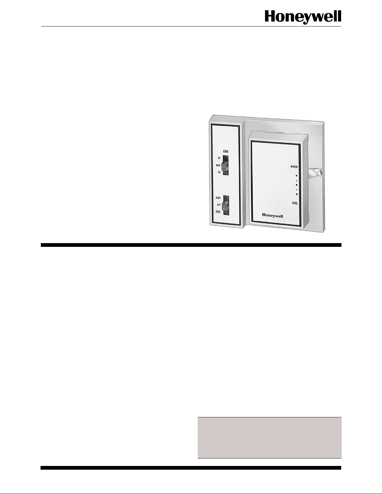
T4039A,B,D-M,S,V
Line Voltage Cooling and
Heating-Cooling Thermostats
T4039 Thermostats Control Line Voltage Valves of
a fan coil unit in cooling, manual changeover heating-cooling, or automatic changeover heating-cooling systems. One or two valves may be controlled
directly by the thermostat. The fan switch (where
applicable) controls air circulation.
■ 1-, 2-, or 3-speed manual fan control available.
■ Positive deadspot separates heating-cooling circuits
in automatic models. Remote changeover switch is
required to separate circuits in manual changeover
heating-cooling models.
■ Scale range is approximately 55° F to 95° F [13° to
35° C] in 10° F [6° C] increments from 75° F [24°
C] midpoint. Scale is marked COOL-WARM.
■ Cooling circuit breaks in FAN-OFF position to re-
duce condensation problems in the fan coil unit.
■ Color-coded leadwires.
■ All models can be mounted on standard vertical
outlet boxes. Models with manual switching can be
mounted on 4 in. square junction boxes or 2ganged outlet boxes.
■ Adjustable range stops limit temperature adjustment or lock at selected setpoint.
■ Models available with separate power source for
fan and thermostat.
CONTENTS
Specifications ................................................. 2
Ordering Information ..................................... 2
Installation ..................................................... 5
Operation ....................................................... 8
Checkout......................................................... 8
J. H. • Rev. 10-92 • ©Honeywell Inc. 1992 • Form Number 60-2241—8
1 60-2241—8
Page 2
T4039A,B,D-M,S,V
SPECIFICATIONS • ORDERING INFORMATION
Specifications
MODELS:
System Switching
Cooling Only Off-On
Cooling Only Hi-Med-Lo T4039B
Heating-Cooling
Heating Cooling
Heating-Cooling
Automatic Heating-Cooling None T4039G
Automatic Heating-Cooling — T4039H
Automatic Heating-Cooling Off-Hi-Lo
Automatic Heating-Cooling Off-Hi-Lo
Automatic Heating-Cooling Hi-Med-Lo
Autoamtic Heating-Cooling Hi-Med-Lo T4039M
Automatic Heating-Cooling Hi-Med-Lo T4039S
Automatic Heating-Cooling Hi-Lo T4039V
a
See Fig. 4 for arrangements of switches.
b
OFF breaks cooling circuit and fan circuit.
c
Remote changeover switch required.
d
OFF breaks both heating and cooling circuits and
c
c
c
Manual
Off-On
— T4039D
Off-On
Off-Hi-Lo
—
Hi-Med-Lo T4039F
Off-On
Off-On
—
Off-On
Off-On
Heat-Off-Cool
Off-On
a
b
b
d
b
b
d
b
d
b
d
d
d
fan circuit.
Model
T4039A
T4039E
T4039J
T4039K
T4039L
ELECTRICAL RATINGS:
A. Thermostat (valve load).
Normal (A) Inrush (B)
120 Vac 0.32 1.00
240 Vac 0.16 0.50
277 Vac 0.14 0.43
B. Fan Switch
Full Load (A) Locked Rotor (A)
120 Vac 5.5 33.0
240 Vac 2.75 16.5
277 Vac 2.4 14.4
10A Resistive at 125 Vac
5A Resistive at 240 Vac
4.2A Resistive at 277 Vac
TEMPERATURE SETTING RANGE: Approximately
55° F to 95° F [13° C to 35° C]; marked COOLWARM in 10° F [6° C] increments from 75° F [24° C]
midpoint.
DIFFERENTIAL: Approximately 2° F [1° C] at mid-
scale. On automatic heating-cooling models, the
differential from make of one contact to make of
the opposite contact is 7° F [4° C] maximum with a
positive deadspot.
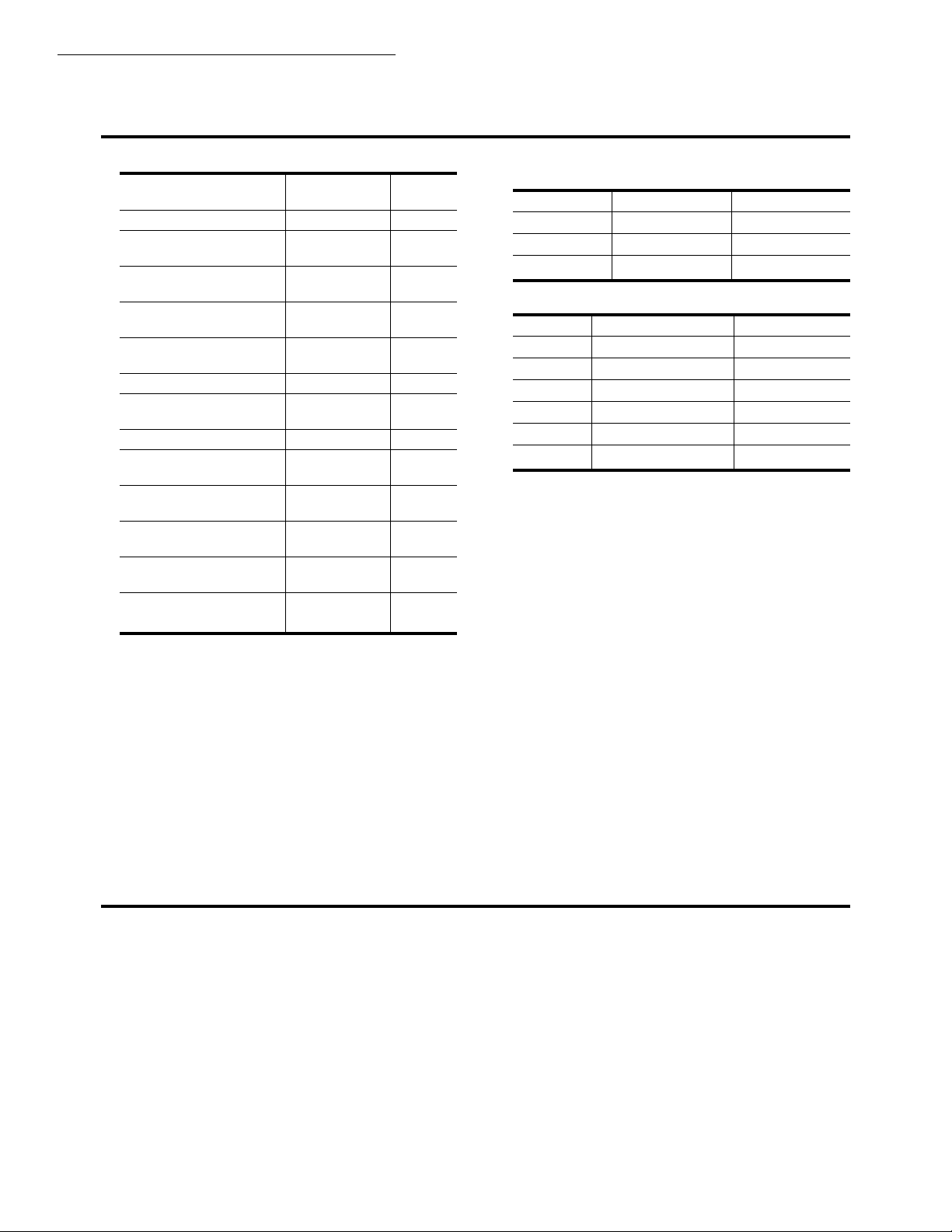
DIMENSIONS: See Figs. 1 and 2.
Ordering Information
When purchasing replacement and modernization products from your TRADELINE® wholesaler or your distributor, refer to the
TRADELINE Catalog or price sheets for complete ordering number, or specify—
1. Model number.
If you have additional questions, need further information, or would like to comment on our products or services, please write or phone:
1. Your local Honeywell Home and Building Control Sales Office (check white pages of your phone directly).
2. Home and Building Control Customer Satisfaction
Honeywell Inc., 1885 Douglas Drive North
Minneapolis, Minnesota 55422-4386 (612) 951-1000
In Canada—Honeywell Limited/Honeywell Limitée, 740 Ellesmere Road, Scarborough, Ontario M1P 2V9. International Sales and
Service offices in all principal cities of the world. Manufacturing in Australia, Canada, Finland, France, Germany, Japan, Mexico,
Netherlands, Spain, Taiwan, United Kingdom, U.S.A.
2
Page 3
T4039A,B,D-M,S,V
SPECIFICATIONS
FINISH: Silver bronze. T4039M is available in white.
MOUNTING: Models without manual switching mount
on standard vertical outlet boxes. Models with manual
switching mount on 4-in. square junction boxes or
2-ganged outlet boxes. Manual switching models may
Fig. 1—Mounting dimensions in in. [mm] of
T4039 models with manual switching.
also mount on a standard vertical outlet box if local
codes permit. See Fig. 3.
UNDERWRITERS LABORATORIES, INC. LISTED: File
No. E4436, Vol. 2, dated 3-19-73; Guide No. XAPX.
Fig. 2—Mounting dimensions in in. [mm] of
T4039 models without manual switching.
3 60-2241—8
Page 4

T4039A,B,D-M,S,V
SPECIFICATIONS
Fig. 3—Mounting T4039.
4
Page 5

T4039A,B,D-M,S,V
INSTALLATION
Installation
WHEN INSTALLING THIS PRODUCT…
1. Read these instructions carefully. Failure to follow
them could damage the product or cause a hazardous
condition.
2. Check the ratings given in the instructions and on
the product to make sure the product is suitable for your
application.
3. Installer must be a trained, experienced service
technician.
4. After the installation is complete, check out product
operation as provided in these instructions.
CAUTION
Disconnect power supply to prevent electrical shock
or equipment damage.
Before mounting, be sure to remove cardboard shipping
inserts that protect the contacts.
1. Remove T4039 cover by loosening the cover screw
with Allen wrench.
2. Open the cardboard inside cover by pressing inward on
the left side to release latch. Do not remove this cover.
3. Carefully remove the shipping inserts from around the
snap contacts.
4. Check contact operation before mounting device.
MOUNTING
Models without manual switching mount on standard
vertical outlet boxes. Models with manual switching
mount on 4-in. square junction boxes or 2-ganged outlet
boxes. Manual switching models can also mount on standard vertical outlet boxes if local electrical codes permit.
Mount thermostat on side wall about 5 ft. [1.5 m] above
the floor. Do not mount where thermostat can be affected by
drafts, radiant heat from the sun or other sources of heat.
Use Allen wrench to open cover and mount according
to Fig. 3. Two mounting screws are provided.
WIRING
Disconnect power supply before beginning installation to avoid electrical shock or equipment damage. All
wiring must comply with local codes and ordinances.
Internal schematic and external connections for the
T4039 are shown in Fig. 4. Use solderless connectors or
other approved methods to wire thermostat into the system. Six-inch color-coded leadwires are provided.
SETTING
The T4039 temperature scale is marked COOL-WARM
with approximate scale divisions of 10° F from 75° F
[24° C] midpoint. The range is approximately 55° F to 95°
F [13° C to 35° C]. Set lever at desired temperature.
To adjust the temperature setpoint range stops, Fig. 3,
locate stops at the desired temperature range setpoint
and insert.
5 60-2241—8
Page 6

T4039A,B,D-M,S,V
INSTALLATION
Fig. 4—Internal schmeatics and external connections for T4039 Thermostats.
BLUE
1
OFF
ON
HI
MED
LO
1
OFF
ON
RISE
YELLOW
ORANGE
BLUE
TAN
YELLOW
RISE
ORANGE
RED
T4039B
RED
TO FAN
T4039A
TO COOLING
CONTROL
L1 (HOT)
L1 (HOT)
TO FAN
SPEED CONTROL
TO COOLING
CONTROL
L1 (HOT)
HI
LO
MED
HI
RISE
T4039F
BLUE
TAN
YELLOW
RISE
BROWN
ORANGE
RED
TO FAN
SPEED CONTROL
TO HEATING
CONTROL
L1 (HOT)
TO COOLING
CONTROL
MED
3
LO
OFF
1
ON
T4039G
RED
RISE
BROWN
ORANGE
TO COOLING
CONTROL
TO HEATING
CONTROL
L1 (HOT)
OFF
ON
1
OFF
HI
LO
BLUE
RED
RISE
RISE
2
YELLOW
ORANGE
T4039D
TO FAN
TO COOLING CONTROL
BROWN
TO HEATING
CONTROL
L1 (HOT)
L1 (HOT)
T4039H
BLUE
RED
RISE
3
OFF
ON
2
YELLOW
ORANGE
TO FAN
TO COOLING CONTROL
BROWN
TO HEATING
CONTROL
L1 (HOT)
L1 (HOT)
3
T4039E
RED
TO COOLING CONTROL
RISE
LO
RISE
BROWN
ORANGE
BLUE
HI
YELLOW
TO HEATING
CONTROL
L1 (HOT)
TO FAN
SPEED CONTROL
1
OFF BREAKS COOLING AND FAN CIRCUITS.
OFF BREAKS HEATING, COOLING AND FAN CIRCUITS.
2
3
SEPARATE POWER SOURCE FOR THERMOSTAT AND
FAN. CONNECT ORANGE AND YELLOW FOR
SINGLE POWER SOURCE IF NEEDED.
M5353
6
Page 7

T4039A,B,D-M,S,V
INSTALLATION
Fig. 4—Internal schmeatics and external connections for T4039 Thermostats
T4039J
TO HEATING
CONTROL
L1 (HOT)
TO FAN
SPEED CONTROL
TO COOLING
CONTROL
TO HEATING
CONTROL
TO FAN
SPEED CONTROL
TO HEATING
CONTROL
L1 (HOT)
TO COOLING
CONTROL
BLACK
HI
MED
LO
OFF
2
4
ON
MED
HI
LO
HI
MED
LO
HEAT
OFF
2
COOL
HI
LO
2
OFF
ON
RISE
OFF
HI
LO
LO
1
M5352
LO
HI
RED
RISE
ORANGE
BLUE
YELLOW
1
TYPICAL T4039K
RED
RISE
2
OFF
HI
HI
MED
LO
OFF
ON
1
OFF BREAKS COOLING AND FAN CIRCUITS.
OFF BREAKS HEATING, COOLING AND FAN CIRCUITS.
2
SEPARATE POWER SOURCE FOR THERMOSTAT AND
3
FAN. CONNECT ORANGE AND YELLOW FOR SINGLE
POWER SOURCE IF NEEDED.
THE WIRE COLORS OF THE T4039K1024 MODEL DIFFER
4
FROM THE TYPICAL T4039K MODELS AS FOLLOWS:
TYPICAL
T4039K
T4039K1024 BROWN RED
LO
HI
YELLOW
ORANGE
BLUE
YELLOW
T4039L
LO
MED
HI
RISE
BLUE
TAN
YELLOW
ORANGE
BLUE
L1 (HOT)
BROWN
RED
RED
BLUE YELLOW
TO COOLING
CONTROL
BROWN
BROWN
TO FAN
SPEED CONTROL
BROWN ORANGE
(Continued).
MED
BLACK
YELLOW
HI
LO
BLUE
RISE
LO
HI
RISE
RED
BROWN
ORANGE
TAN
YELLOW
BLUE
BROWN
ORANGE
RED
BROWN
RED
BLUE
YELLOW
T4039M
T4039S
TO FAN
SPEED CONTROL
T4039V
TO FAN
SPEED CONTROL
TO COOLING
CONTROL
BLACK
TO FAN
SPEED CONTROL
TO COOLING
CONTROL
TO HEATING
CONTROL
L1 (HOT)
TO HEATING
CONTROL
L1 (HOT)
TO COOLING
CONTROL
TO HEATING
CONTROL
L1 (HOT)
7 60-2241—8
Page 8

Operation
In heating applications, as the temperature drops, the
thermostat heating contacts make to open a valve that
allows hot water to flow through the coil. On select models,
the speed at which the heat is circulated is controlled
manually by the fan switch.
In cooling applications, as the temperature rises, the
thermostat cooling contacts close to open a valve that
allows cold water to flow through the coil. Cooling mechanism will not operate if manual switch is in the OFF
position. Models T4039D,H,K,M,S,V will also turn off
the heating valve when the manual switch is in OFF.
Check the T4039 before leaving the installation. Raise
the temperature setting to start the heating cycle or lower
In manual changeover heating-cooling models, the
thermostat must be used with a remote changeover switch
or control to select the proper heating or cooling cycle
for the thermostat.
CALIBRATION
The T4039 is accurately calibrated at the factory under
controlled conditions. Do not attempt to field calibrate
this device.
Checkout
the setting to start the cooling cycle. Check both cycles
on heating-cooling models.
Home and Building Control Home and Building Control
Honeywell International, Inc. Honeywell Limited—Honeywell Limitée
1985 Douglas Drive North 35 Dynamic Drive
Golden Valley, MN 55422 Scarborough, Ontario
M1V 4Z9
8
 Loading...