

Honeywell ST9500C Installation Instructions Manual
Mounting
The Programmer should be mounted at a level where the display can be
seen clearly, (1.2 to1.5m from the floor) and the ambient temperature is
within the range of 0 to 40°C. The ST9500 is for use in normal domestic
environments.
CAUTION
Isolate power supply and make safe before wiring the unit to prevent
electric shock and equipment damage. Installation should be carried
out by a qualified electrician or competent heating engineer.
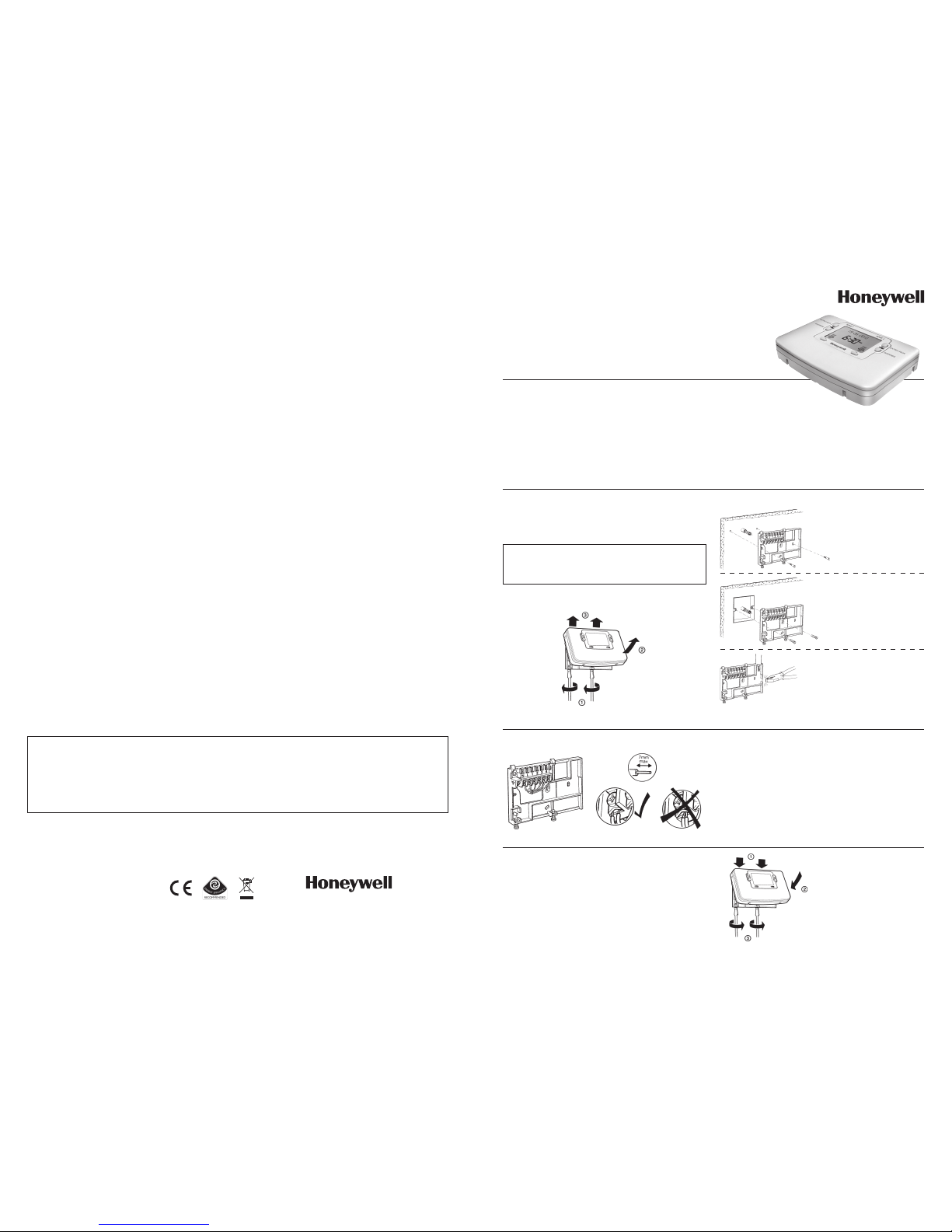
To remove the unit from the wall-plate, slacken the two securing screws at
the bottom of the ST9500 and hinge the unit up to separate the two halves.
50022736-007 A
© 2007 Honeywell International Inc.
ST9500C 2-Zone Programmer
INSTALLATION INSTRUCTIONS
50022736-007 A
Introduction
ST9500 is an Electronic Programmer which provides accurate time
control for central heating systems with separate 7 day programmes for
two independent heating zones.
ST9500 Programmers can be combined with other Honeywell controls such
as Room Thermostats, Cylinder Thermostats, Wiring Centres and Zone or
Diverting Valves to form a fully automatic central heating control system.
4 1
Honeywell Control Systems Ltd.
Arlington Business Park,
Bracknell
Berkshire
RG12 1EB
Technical Help Desk: 08457 678999
www.honeywelluk.com
Specification
Power Supply: 230V~, 50…60Hz, 10W
Switch Action: 2 x SPDT
Switch Rating: 230V~, 50…60Hz, 3(3)A
Factory set clock
Power Reserve: lifetime battery
Programmes/Settings: permanently stored in NV RAM
Approvals: Conforms to protection requirements of
Directives 2006/95EC and 89/336EC
Mounting Options
RECOMMENDED CLEARANCE DISTANCES:
ABOVE WALLPLATE: 110mm
BELOW WALLPLATE: 100mm
LEFT/RIGHT OF WALLPLATE: 10mm
a. Sur face mounting
concealed wiring
b. Flush switchbox
Fixing holes are
spaced to suit BS4662
requirements
c. Sur face mounting with
surface wiring in
mini trunking
Wiring
ALL WIRING MUST BE IN ACCORDANCE WITH I.E.E. REGULATIONS.
THIS UNIT IS FOR FIXED WIRING ONLY.
A switch, having contact separation of at least 3mm in all poles (formerly
Class ‘A’), must be incorporated in the fixed wiring as a means of
disconnecting the supply.
The unit is a Class II (double insulated) device. A parking terminal is
provided for external earth continuity.
The system must be appropriately fused. A fuse rated at no more than
3 Amps should be installed.
The unit has 4 knockouts for surface wiring, care must be taken to ensure
that the cable or mini-trunking completely fills the knockout hole without
leaving any gaps.
Final Assembly
Clip the unit onto the hinges on the top of the wallplate and hinge down
into position. Tighten the two securing screws using a screwdriver.
Switch on the power – the unit will now be operating according to the
built-in programme. Note : the ST9500 is supplied with a factory set
clock for faster installation .
Refer to ST9500 User Guide for programming details.
Replacing Other Manufacturers’ Time Controls
Refer to Honeywell for wiring conversion diagrams.
Completion Checklist for Installation
1. Check unit powers up correctly, and that the display does not remain blank.
2. Set Zone 1 and Zone 2 operating modes to AUTO and switch Zone 1 and Zone 2 on and off using the OVERRIDE buttons, to ensure the system
is operating correctly.
3. Check the factory-set day, date, and time are correct and adjust if necessary. Refer to the User Guide for details.
4. If required, enter Installer Mode and adjust Installer Parameters to match the lifestyle and needs of the User. Remember to make a note of these
parameter changes in the Configuration Data section of the User Guide. Also note here how the zones have been set.
5. Explain the operation of the product to the User and help them to set their Zone 1 and Zone 2 programmes. There are 3 built-in profiles that can
be used as a basis for typical User programmes.
6. If required, attach the self-adhesive programme guide label to the underside of the cover flap. The label is supplied in the box and requires to be
peeled away from the backing material before use. Write details of how the zones have been configured in the space provided.
7. Explain when the User should contact someone to arrange a Service Visit.
8. Write the date of installation, your name and telephone number in the space provided in the User Guide, in the section ‘Boiler & System Service
Log’
9. Remember to leave the User Guide and Installation Instructions with the User and remind them to keep them in a safe place. This forms part of a
Home Information Pack.
This product and its associated documentation and packaging are protected by various intellectual property rights belonging to Honeywell Inc and its subsidiaries
and existing under the laws of the UK and other countries. These intellectual and property rights may include patent applications, registered designs, unregistered
designs, registered trade marks, unregistered trade marks and copyrights.
Honeywell reserves the right to modify this document, product and functionality without notice. This document replaces any previously issued instructions and is only
applicable to the product(s) described.
This product has been designed for applications as described within this document. For use outside of the scope as described herein, refer to Honeywell for guidance.
Honeywell cannot be held responsible for misapplication of the product(s) described within this document.
Manufactured for and on behalf of the Environment and Combustion Controls Division of Honeywell Technologies Sarl, Ecublens, Route du Bois 37, Switzerland by its
Authorised Representative Honeywell Inc.
Ensure the mounting surface is supporting and fully covers the wiring
wall-plate.
2 ST9500C Programmer Installation Guide 3
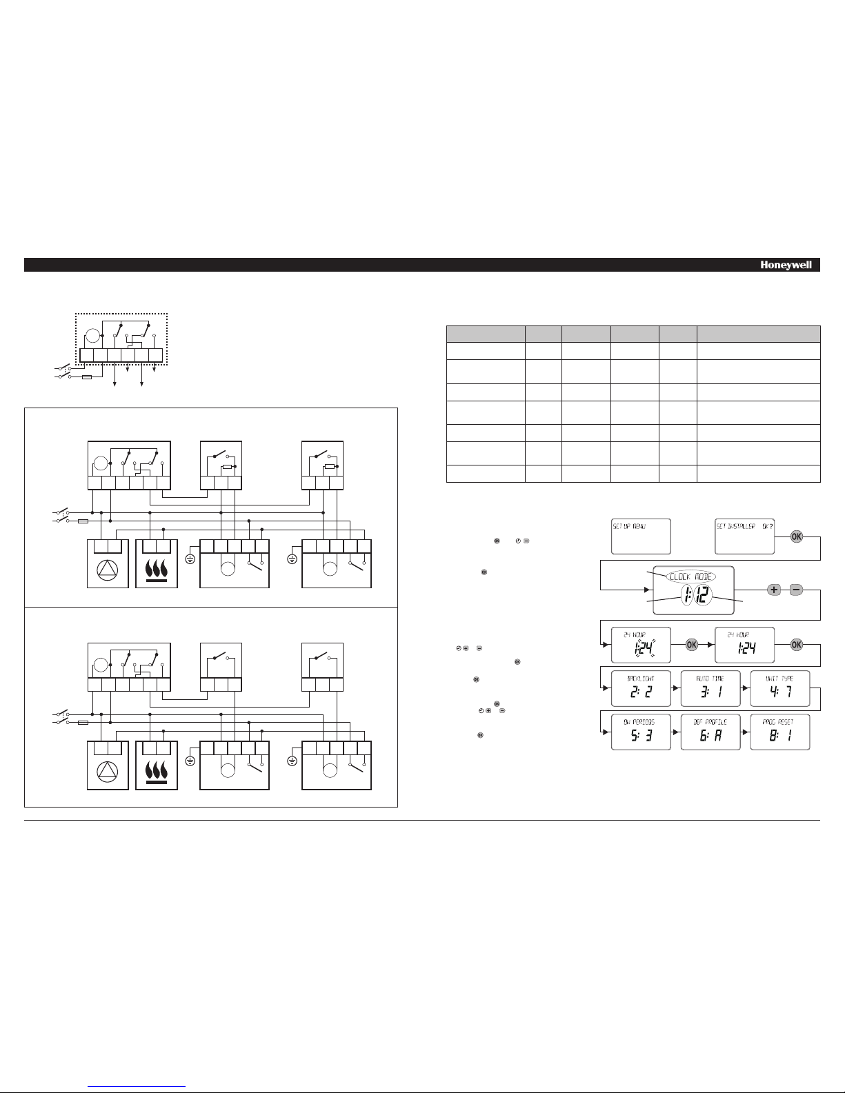
WIRING CONNECTIONS
ST9500 Internal Wiring
Notes
1. The ST9500 is a Class II (double insulated) device. A parking
terminal is provided for earth wiring continuity, if required.
2. In the wiring schematics below, connections are shown to basic
boilers only. For wiring connections to Pump over-run boilers
refer to the boiler manufacturers instructions or to Honeywell for
assistance.
3. Wiring schematics are shown for 2-Zone control using ST9500C and
2 Zone-valves. Please refer to Honeywell for other wiring and control
options.
Control using Zone-valves: Wiring to Mechanical Thermostats
ADDITIONAL PRODUCT FEATURES
Installer Mode
The ST9500 has a special Installer Mode where some features can be adjusted to suit user lifestyle or preferences – these are called installer
Parameters, and are listed in the table below, along with a description of the options that are possible.
INSTALLER PARAMETER Parameter
Number
LoT™ Display
Description
Default Value Range of
Values
Description [LoT™ Display Description]
24hr or am/pm clock display 1 CLOCK MODE 12 12, 24 12 = am/pm display,
24 = 24hr display
[AM-PM]
[24 HOUR]
Configure backlight operation
(backlight consumes no
additional energy)
2 BACKLIGHT 2 0, 1, 2 0 = off,
1 = on if button pressed,
2 = on continuously
[NO B-LIGHT]
[B-L DELAY]
[B-LIGHT ON]
Enable/disable auto time
change
3 AUTO TIME 1 0, 1 0 = disabled,
1 = enabled
[NO CHANGE]
[TIME CHANGE]
1-day or 5/2-day or 7-day
operation
4 UNIT TYPE 7 1, 5, 7 1 = 1-day operation,
5 = 5/2-day operation,
7 = 7-day operation
[1-DAY]
[5-2 DAY]
[7-DAY]
Number of ON/OFFs per
day
5 ON PERIODS 3 2, 3 2 = 2 on/offs per day,
3 = 3 on/offs per day
[2 PER DAY]
[3 PER DAY]
Select default time
programme
6 DEF PROFILE A A, b, C A = standard,
b = at home,
C = economy
[PROFILE A]
[PROFILE B]
[PROFILE C]
* Reset all parameters 8 PROG RESET 1 0, 1 0 = do not reset
1 = default parameters
[RESET OFF]
[RESET ON]
To Enter Installer Mode:
a.
Ensure the slider is in the RUN position, then press
and hold the and buttons together for 8
seconds. Ignore the ‘NOT VALID’ that is displayed
for a few seconds. The message ‘SET UP MENU’ will
show briefly, followed by ‘SET INSTALLER OK ?’
b. Press the button to take you into the Installer Mode
Parameter Menu.
c. Parameter 1 is now available to change. This is to
allow you to change the clock format from 12 hour
AM/PM to 24 hour. At every step, the LoT™ Display
will inform you what the parameter means and what
option you have selected. The parameter number is
shown on the display separated by a colon from the
parameter value.
d. You can change the parameter value by pressing the
or buttons. At this point the description in the
LoT™ Display will change and the parameter value
will flash. If you press the value will stop flashing
and will be saved for use.
e. Press to move to the next parameter available
for editing. The parameter number will change
accordingly.
f. Keep pressing to step around the list of parameters,
and use or buttons to change the parameter
value.
g. Any parameter changes that have been confirmed
with the button will be saved and used.
* this parameter by default has a value of 1, unless you change any other parameter, when it will change to 0. Set it to 1 to reset all parameters back to defaults.
LoT™ Display
Parameter
Number
Parameter
Value
or
Clock
N L 1 2 3 4
3 AMPS MAX
Zone 1
OFF
Zone 1
ON
Zone 2
OFF
Zone 2
ON
N
L
OFF ON OFF ON
To Exit Installer Mode:
You can exit Installer Mode at any time by moving the slider to the next position and then back again to RUN.
Note: Installer Mode will exit automatically after 10 minutes if the slider is not moved.
230V~
50...60Hz
Clock
N L 1 2 3 4
3 AMPS MAX
N
L
OFF ON OFF ON
230V~
50...60Hz
1 2 3
ST9500
1 2 3
T6360B (ZONE 2) T6360B (ZONE 1)
PUMP
N L
BOILER
N L
V4043H (ZONE 2)
G/Y BL BR GR O
M
V4043H (ZONE 1)
G/Y BL BR GR O
M
Control using Zone-valves: Wiring to Digital Thermostats
Clock
N L 1 2 3 4
3 AMPS MAX
N
L
OFF ON OFF ON
230V~
50...60Hz
A B
ST9500
A B
T6620B (ZONE 2) T6620B (ZONE 1)
PUMP
N L
BOILER
N L
V4043H (ZONE 2)
G/Y BL BR GR O
M
V4043H (ZONE 1)
G/Y BL BR GR O
M
 Loading...