


DESCRIPTION
FEATURES
POTENTIAL APPLICATIONS
The SS351AT and SS451A sensors are small, versatile digital
Hall-effect devices that are operated by the magnetic field from
a permanent magnet or an electromagnet. They are designed
to respond to a either a North pole or a South pole.
These omnipolar sensors are sensitive and flexible devices
designed to meet a wide range of potential applications. The
SS351AT and SS451A have a typical operating point of 85 G
at 25 °C [77 °F]. Because they can be operated by a North
pole or a South pole, they do not require the magnet polarity to
be identified, thus making the installation easier and potentially
reducing the system cost.
These sensors are available in two package styles. The
SS351AT is available in the subminiature SOT-23 surface
mount package; the SS451A is available in the leaded, flat TO92-style package. The SS351AT’s small size requires less PC
board space, allowing it to be used in smaller assemblies. Its
3 Vdc capability allows for use in low voltage applications,
promoting energy efficiency.
The SS351AT is available on tape and reel (3000 units per
reel); the SS451A is available in a bulk package (1000 units
per bag).
Subminiature package size (SS351AT) supplied on tape
and reel allows for a compact design with automated
component placement, helping to reduce manufacturing
costs
Simple activation from a North pole or a South pole and
sensitive magnetics make this omnipolar product suitable
in a variety of potential motion control, lid closure
detection, and displacement sensing applications
Low voltage 3 Vdc capability helps reduce power
consumption
Built-in reverse polarity protection protects the device from
potential damage during installation
Thermally balanced integrated circuit provides for stable
operation over a wide temperature range of -40° to
150 °C [-40 °F to 302 °F]
RoHS-compliant materials meet Directive 2002/95/EC
Commercial:
Speed and RPM (revolutions per minute) sensing in
fitness equipment
Magnetic encoder for building access
Damper or valve position control in HVAC (heating,
ventilation and air conditioning) equipment
Flow rate sensing in appliances and water softeners
Printer head position sensing
Industrial:
Flow rate sensing in industrial processes
Robotic control (cylinder position monitoring)
Float-based fluid level sensing
Medical:
Displacement sensor in hospital beds and medical
equipment
Medication bin monitor on portable drug carts
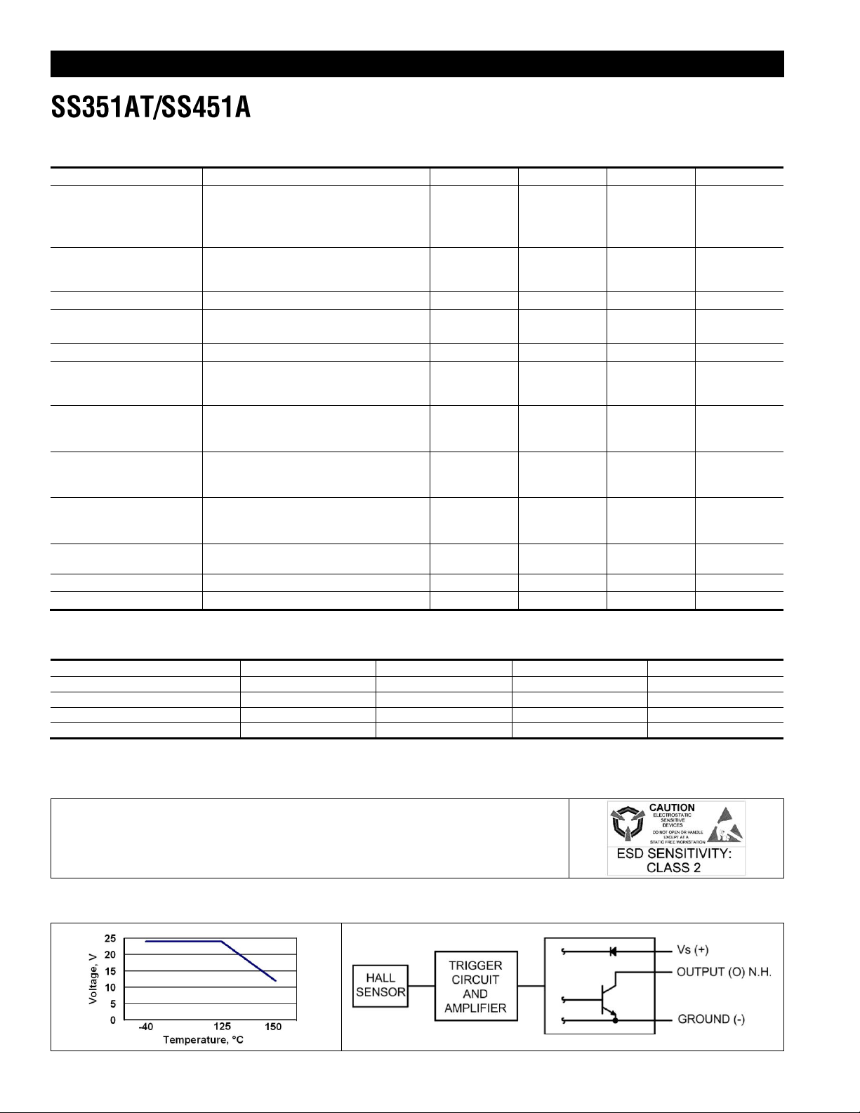
Table 1. SS351AT/SS451A Specifications (At Vs=3.0 Vdc to 24 Vdc, 20 mA load, TA = -40 °C to 150 °C [-40 °F to 257 °F])
Characteristic
Condition
Minimum
Typical
Maximum
Unit
Supply voltage1:
Vdc
SS451A
-40 °C to 150 °C [-40 °F to 302 °F]
3 – 24
SS351AT
-40 °C to 125 °C [-40 °F to 257 °F]
3 – 24
SS351AT
150 °C [302 °F]
3 – 12
Supply current
Vsupply = 5 V at 25 °C [77 °F]
Vsupply = 3 V at 25 °C [77 °F]
–
–
–
4.5
3.5
–
6
5 9 mA
Output Current
–
– – 20.0
mA
Vsat
at 20 mA, gauss > Bop positive
or gauss < Bop negative
– – 0.4
V
Output leakage current
gauss > Bop+ or < Bop-
– – 10
µA
Output switching time:
rise
fall
Vsupply = 12 V at 25 °C [77 °F],
RL =1.6 KOhm, CL = 20 pF
–
–
–
–
1.5
1.5
µs
Thermal resistance:
–
°C/W
SS451A
–
233
–
SS351AT
–
303
–
SS351AT/SS451A:
–
gauss
Operate positive
35
85
135
Operate negative
-135
-85
-35
SS351AT/SS451A:
–
gauss
Release positive
10
50
120
Release negative
-120
-50
-10
SS351AT/SS451A
gauss
Differential
–
5
35
80
Operating temperature
–
-40 [-40]
–
150 [302]
°C [°F]
Storage temperature
–
-40 [-40]
–
150 [302]
°C [°F]
Characteristic
Minimum
Typical
Maximum
Unit
Supply voltage
-28.0
–
28.0
V
Applied output voltage
-0.5 – 28.0
V
Output current – –
20
mA
Magnetic flux – –
no limit
gauss
NOTICE
Absolute maximum ratings are the extreme limits that the device will withstand without
damage to the device. However, the electrical and mechanical characteristics are not
guaranteed as the maximum limits (above recommended operating conditions) are
approached, nor will the device necessarily operate at absolute maximum ratings.
Figure 1. SS351AT Rated Supply Voltage
Figure 2. Current Sinking Output Block Diagram
Note 1: See Figure 1.
Table 2. SS351AT/SS451A Absolute Maximum Ratings1
Note 1: The magnetic field strength (gauss) required to cause the switch to change state (operate and release) will be as specified
in the magnetic characteristics. To test the switch against the specified magnetic characteristics, the switch must be placed in a
uniform magnetic field.
2 www.honeywell.com/sensing
 Loading...