

Page 1
SP970A, B, C and D Manual and
Minimum Position Pressure Regulators
INSTALLATION INSTRUCTIONS
DESCRIPTION
The SP970A, B, C and D Manual and Minimum Position
Pressure Regulators provide regulated pressure to a
(22)
60
40
20
0
FRONT VIEW SIDE VIEW
1-9/16
(40)
80
2-1/4
100
(57)
2-1/2
(63)
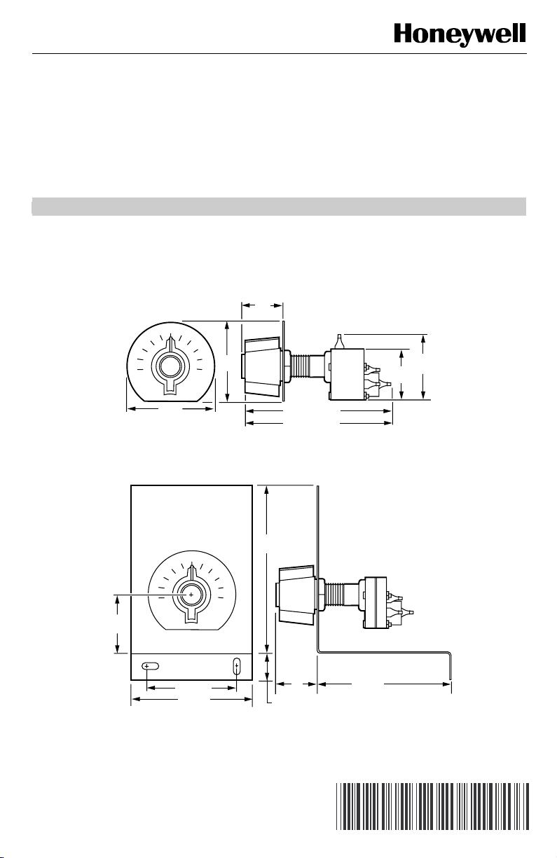
Fig. 1. SP970A and C dimensions in in. (mm).
60
40
20
0
80
100
controlled device such as a pneumatic damper operator.
It provides either manually set pressure or manually set
minimum pressure with variable maximum pressure.
Figs. 1 and 2 show approximate dimensions.
7/8
1-7/8
(48)
1-1/2
(38)
SP970C 3-7/8 (98)
4-1/2
(114)
SP970A 3-1/2 (89)
C4857
2-1/16 (62)
3-1/4 (83)
FRONT VIEW
Fig. 2. SP970B and D dimensions in in. (mm).
® U.S. Registered Trademark
Copyright © 2002 Honeywell •All Rights Reserved
7/8
(22)
(25)
1
3-1/2 (89)
SIDE VIEW
C4858
95-7237EF
Page 2
SP970A, B, C AND D MANUAL AND MINIMUM POSITION PRESSURE REGULATORS
BEFORE INSTALLATION
SP970A and C only
For panels having a thickness greater than 5/16 in.
(8 mm) but less than one in. (25 mm), use 315677A Bus
Assembly.
INSTALLATION
Mounting
The SP970A and C can be panel, surface or wall
mounted. The SP970B and D are surface or wall
mounted. See Fig. 3 and 4.
8 PSI
CENTER PUNCH MARK IN "V" GROOVE
SHOWING 8 PSI (55 kPa) CALIBRATION ENLARGED
SP97O
HEX NUT
CENTER
PUNCH
MARK
IN "V"
GROOVE
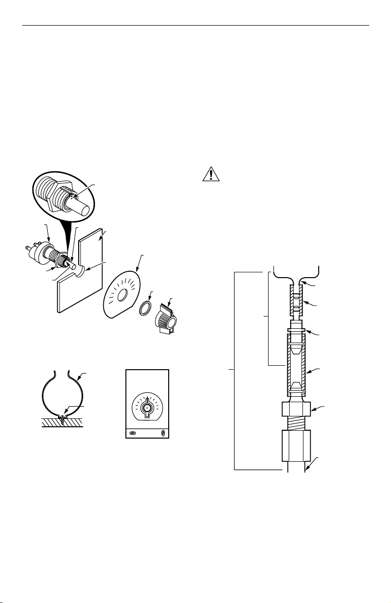
Fig. 3. SP970A and C panel mounting.
SP970A AND C
SP970 SWITCH
Fig. 4. SP970 surface or wall mounting.
Panel Mounting SP970A and SP970C
1. Drill a 5/8 in. (16 mm) hole.
2. Lock the SP970 switch and scaleplate to the panel
with a hex nut on the back of the panel. Use a second hex nut on the front panel. See Fig. 3.
MOUNTED
HERE
SHAFT
SCREW
SPRING
CLIP
C8275
PANEL-UP TO 5/16 IN.
(8MM) THICK
5/8 IN. (16MM)
DIA. HOLE
60
80
40
100
20
0
SP970B AND D
40
20
0
SCALEPLATE
HEX NUT
60
80
100
C8277
KNOB
C8278
NOTES:
√ The scaleplate, knob and two mounting nuts
are furnished with SP970A and C.
√ Do not mount the knob during installation.
Refer to the Calibration section of this document.
Surface Mounting
Use the mounting bracket as a template and secure
mounting bracket to surface. See Fig. 4. Screws are not
provided.
Piping
All connections are sharp barb 5/32 in. (4 mm) O.D.
polyethylene tubing.
CAUTION
Equipment Damage Hazard.
To prevent damage to the sharp barb
connections, do not attempt to cut or pull tubing.
To remove the tubing from the barb connections,
cut tubing a few inches from the control device.
Use a coupling to reconnect tubing.
NOTES: When the system is not copper or polyethylene
tubing, adapt as shown in Fig.5. Some models
provide parts for adapting.
SP970A-D
POST FOR
5/32 IN. (4 MM) O.D.
PLASTIC TUBING
CONNECT
1/4 IN.
(6 MM)
PLASTIC
CONNECT
1/4 IN.
(6 MM)
COPPER
Fig. 5. Adaptation piping.
Port Identification Table
The two right columns in Table 1 identifies the ports of
older Honeywell pneumatic relays when upgrading
installation.
5/32 IN. (4 MM)
O.D. PLASTIC
TUBING CUT
TO LENGTH
5/32 IN. X 1/4 IN.
(4 MM X 6 MM)
O.D. PLASTIC
CONNECTOR
(CCTI606B)
1/4 IN. (6 MM)
O.D. PLASTIC
TUBING CUT TO
LENGTH
1/4 IN. (4 MM) O.D.
PLASTIC/COPPER
ADAPTER
(CCTI633BT)
1/4 IN. (6 MM) O.D.
COPPER TUBING
C8276
95-7237EF 2
Page 3
SP970A, B, C AND D MANUAL AND MINIMUM POSITION PRESSURE REGULATORS
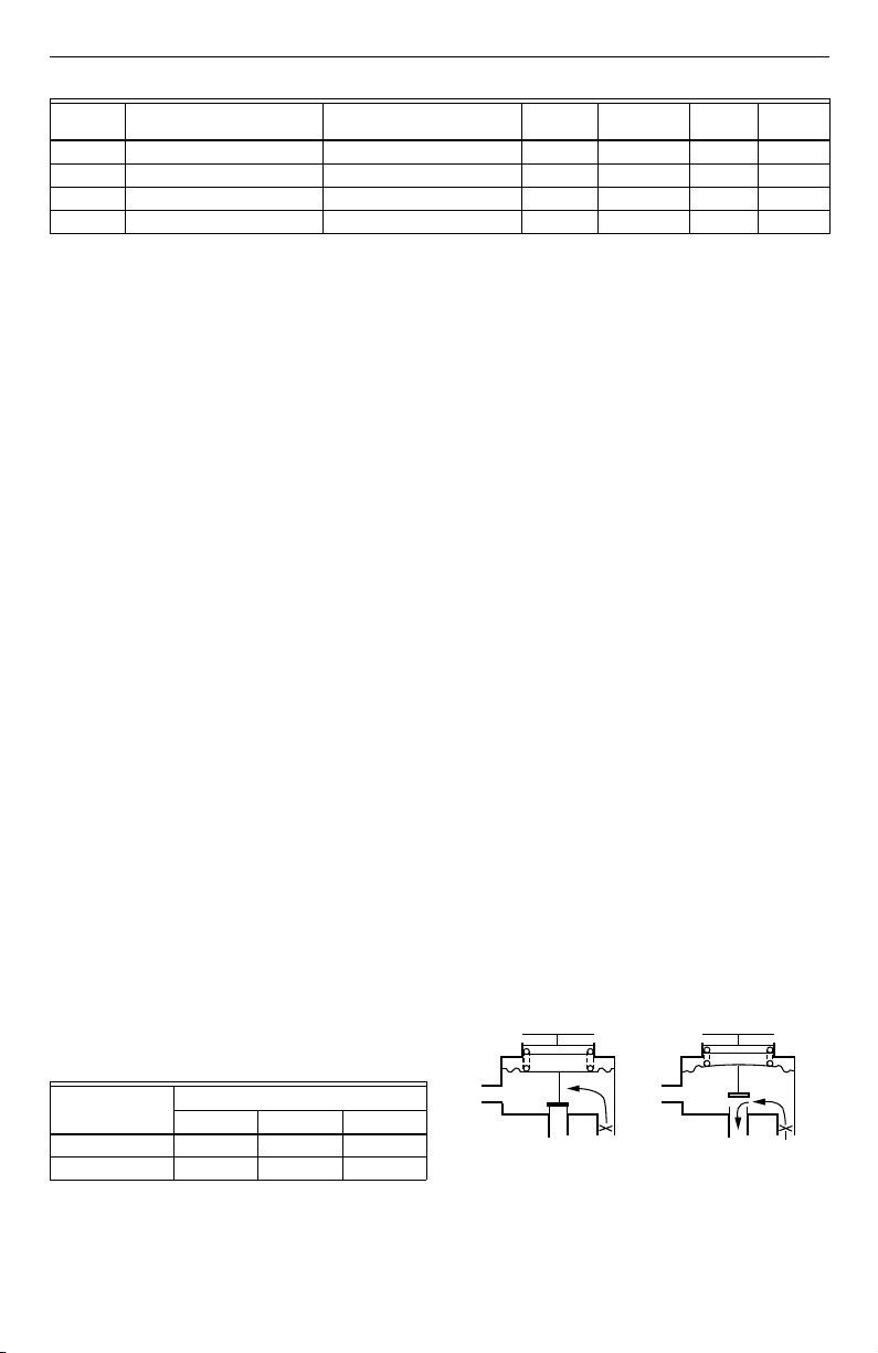
Table 1. Port Identification.
SP970A Pressure
Regulator SP970A Minimum Position SP970B SP970C, D SP92 SP93
Main 1 1 1 1 2 M
Pilot √ 4 √ 3 4 P
Branch 2 2 2 2 3 B
Exhaust 4 √ 4 4 √ √
Calibration
All SP970A and C models are calibrated at 8 psi (55 kPa)
when the calibration mark (center punch) on the shaft is
centered at the bottom of the molded V. To calibrate,
align the center punch mark on the shaft with the bottom
of the molded V groove on the plastic surrounding shaft.
See Fig. 3. This setting equals 8 psi (55 kPa). Secure the
knob to the shaft at the proper scale setting. The knob
should be pointing to 8 psi (55 kPa). See Fig. 4.
All SP970B and D models are calibrated at 8 psi (55 kPa)
when the knob is set at 50 percent.
The large range device can be field recalibrated to other
end points with the same span from 0 psi (0 kPa) lower
limit to 26 psi (179 kPa) upper limit. The small range
device can be field recalibrated to other end points with
the same span from 0 psi (0 kPa) lower limit to 16 psi
(110 kPa) upper limit.
Checkout and Test for All Models
1. With main air connected, insert a pressure gage
into the branch line.
2. Check pressures equivalent to knob settings.
3. When minimum position is used, attach input and
increase pilot pressure.
4. Verify correct operation.
ENGINEERING DATA
Specifications
Models:
- SP970A: A bleed type pressure regulator.
- SP970B: A bleed type pressure regulator mounted
on a sheet metal panel.
- SP970C: A bleed type pressure regulator with a
dead ended pilot chamber for minimum pressure
applications.
- SP970D: A bleed type pressure regulator with a
dead ended pilot chamber for minimum pressure
applications mounted on a sheet metal panel.
Selectable Spans for psi (kPa): See Table 2.
Table 2. Selectable Spans.
Knob Rotation
Model
188 244 300
Small span 5 (34) 6.5 (45) 8 (55)
Large span 10 (69) 13 (90) 16 (110)
a
The setpoint knob normally rotates 188 degrees. Two
breakaway stops on the knob allow rotation of 244 and
300 degrees.
a
Operating Pressure (Switch and Pilot) Range:
Normal Main: 18 psi (124 kPa)
Branch: 3 to 15 psi (21 to 103 kPa)
Pilot: 3 to 15 psi (21 to 103 kPa)
Maximum Safe Air Pressure: 30 psi (207 kPa)
Ambient Operating Limits:
Temperature: 0 to 140°F (-18 to 60°C)
Relative Humidity : 5 to 95%
Air Handling Capacity:
SP970A, B: above minimum position, device feeding
pilot determines capacity. Below minimum position,
air capacity is 0.022 scfm (10 ml/s)
SP970C, D: 0.022 scfm (10 ml/s)
Air Consumption: 0.022 scfm (10 ml/s)
Scaleplate: All models ship with a 0 to 100 scaleplate
(including knob and locknuts).
Construction: Molded plastic with neoprene diaphragm,
steel spring and shaft.
Operation
SP970A and B: Three Port Switches
PRESSURE REGULATOR OPERATION
Main line air flows through the restriction into the
branchline chamber and out the nozzle. Branchline
pressure increases until it is strong enough to compress
the spring and lift the diaphragm off the nozzle. Airflow
out the nozzle is controlled by the balance between the
branchline pressure and spring force.
MINIMUM POSITION OPERATION
An external signal is connected to port 4 (exhaust port).
When the external signal is greater than the spring load,
the nozzle opens and branchline pressure is the same as
the external signal. When the external signal is less than
the spring load, branchline pressure is controlled as
described in the previous paragraph. See Fig. 6.
2 2
BRANCH
PILOT
4
MAIN
Fig. 6. SP970A/B operation.
SP970A,B
BRANCH
1
PILOT
4
SP970A,B
MAIN
1
C4298
3 95-7237EF
Page 4

SP970A, B, C AND D MANUAL AND MINIMUM POSITION PRESSURE REGULATORS
SP970C and D: Four Port Switches
These minimum position devices have a separate dead
ended chamber connected to port 3 to receive an
external signal. When the external signal is less than the
spring load, the signal has no effect and functions similar
PILOT
CHAMBER
3
PILOT
BRANCH
3
A. BUILDING TO MINIMUM SETTING
3
PILOT
BRANCH
3
B. BALANCED AT MINIMUM SETTING
SP970C,D
4
VENT MAIN
SP970C,D
4
VENT MAIN
Fig. 7. SP970C and D operation.
Application
Fig. 8A shows a typical manual position application using
the three port SP970A, B. This control system manually
positions a damper between OPEN and CLOSED.
Turning the setpoint knob clockwise increases the
branchline pressure to the damper actuator and opens
the damper. Turning the position knob counterclockwise
decreases the branchline pressure and closes the
damper.
The three port SP970A, B is also used with a controller
for automatic damper positioning with minimum position.
See Fig. 8B. When the external signal is less than the
to the SP970A, B as a pressure regulator. When the
external signal is greater than the spring load, the spring
load is isolated and the device duplicates the input
signal. See Fig. 7.
SP970C,D
DISC
3
PILOT
BRANCH
1
1
3
C. PILOT BUILDING BRANCH ABOVE
MINIMUM SETTING
3
PILOT
BRANCH
3
D. BALANCED AGAINST PILOT
knob setting, the spring maintains the branchline
pressure as previously described. When the external
signal rises above the knob setting, air from the signal
flows directly to the branch. During steady state
conditions, the external automatic controller must be
capable of exhausting the air flowing through the exhaust
(pilot) port 4.
Fig. 8C shows a typical four port SP970C, D application.
The minimum position switch keeps the pneumatic
actuator at a minimum position until the thermostat
pressure is greater than the minimum position valve. The
thermostat then controls the actuator.
4
VENT MAIN
SP970C,D
4
VENT MAIN
1
1
C4300
DAMPER DAMPER
ACTUATOR ACTUATOR ACTUATOR
BRANCH
2
M
1
EXH
A. MANUAL POSITION
APPLICATION
4
SP970A OR B
BRANCH BRANCH
2
M
1
2
4
SP970A OR B
M
1
CONTROLLER
B. MINIMUM POSITION C. MINIMUM POSITION
APPLICATION WITH APPLICATION
CONTROLLER INPUT WITH THERMOSTAT
EXH
DAMPER
2
M
1
SP970C OR D
3
4
M
INSERTION
THERMOSTAT
C8279
Fig. 8. Typical SP970 application.
Automation and Control Solutions
Honeywell Honeywell Limited-Honeywell Limité e
1985 Douglas Drive North 35 Dynamic Drive
Golden Valley, MN 55422 Scarborough, Ontario
95-7237EF J.H. Rev. 2-02 customer.honeywell.com
M1V 4Z9
Printed in U.S.A. on recycled
paper containing at least 10%
post-consumer paper fibers.
Page 5

Sélecteurs de pression manuels et à
position minimale SP970A, B, C et D
NOTICE D'INSTALLATION
DESCRIPTION
Les appareils SP970 A, B, C et D sont utilisés pour régler
la pression destinée aux appareils asservis tels que les
servomoteurs pneumatiques de registres. Ils servent à
22
(7/8)
60
40
20
0
VUE DE FACE VUE DE PROFIL
40
(1-9/16)
80
57
100
(2-1/4)
63
(2-1/2)
Fig. 1. Encombrement des SP970A et C, en mm (po).
60
40
20
0
(4-1/2)
80
100
régler manuellement soit la pression d'air soit la pression
minimale dans les applications à pression maximale
variable.
Les Fig. 1 et 2 donnent l'encombrement approximatif des
appareils.
48
(1-7/8)
38
(1-1/2)
SP970C 98 (3-7/8)
SP970A 89 (3-1/2)
114
CF4857
62 (2-1/16)
83 (3-1/4)
VUE DE FACE VUE DE PROFIL
Fig. 2. Encombrement des SP970B et D, en mm (po).
® Marque de commerce déposée aux É.-U.
Copyright © 2002 Honeywell • Tous droits réservés
22
(7/8)
25
(1)
89 (3-1/2)
CF4858
95-7237EF
Page 6

SÉLECTEURS DE PRESSION MANUELS ET Ω POSITION MINIMALE SP970A, B, C ET D
AVANT D'INSTALLER CE PRODUIT…
Modèles SP970A et C seulement
Sur un panneau dont l'épaisseur est supérieure à 8 mm
(5/16 po) mais inférieure à 25 mm (1 po), utiliser un
ensemble bus 315677A.
INSTALLATION
Montage
Les SP970A et C peuvent être montés sur un panneau,
en surface ou sur un mur. Les modèles SP970B et D
peuvent être montés en surface ou sur un mur. Voir les
Fig. 3 et 4.
55 kPa
VUE AGRANDIE - MARQUE AU POINTEAU ALIGNÉE SUR LA RAINURE EN
«V», MONTRANT L'ÉTALONNAGE À
55 kPa (8 psi)
SP97O
ÉCROU
HEXAGONAL
MARQUE
AU POINTEAU
ALIGNÉE SUR
LA RAINURE
EN «V»
Fig. 3. Montage des SP970 A et C sur un panneau.
SP970A ET C
SP970 MONTÉ
À CET
ENDROIT
ARBRE
PINCE À
RESSORT
VIS
PANNEAU D'UNE ÉPAISSEUR
MAXIMALE DE 8 mm (5/16 po)
TROU DE
0
16 mm
(5/8 po)
DIAM.
20
40
ÉCHELLE
60
80
100
SP970B ET D
60
40
20
0
ÉCROU
HEXAGONAL
BOUTON
80
100
CF8278
REMARQUES :
√ L'échelle, le bouton et les deux écrous
de montage sont fournis avec les SP970A
et C.
√ Ne pas poser le bouton au moment de
l'installation. Consulter la section Étalonnage de la présente notice technique.
Montage en surface
Utiliser le support de montage comme gabarit, puis le
fixer à la surface. Voir la Fig. 4. Les vis ne sont pas
fournies.
Tuyaux
Tous les raccords sont effectués avec des tuyaux à crans
en polyéthylène de 4 mm (5/32 po) de diam. ext.
MISE EN GARDE
Risque de dommage matériel.
Ne pas couper ni tirer les canalisations afin de ne
pas endommager les raccords à crans. Pour
enlever la canalisation fixée au raccord à crans,
la couper à quelques centimètres au-dessus du
dispositif de régulation puis la raccorder au
moyen d'un manchon.
REMARQUE : Si les canalisations ne sont pas en cuivre
RACCORD EN
CUIVRE DE
6 mm (1/4 po)
ou en polyéthylène, suivre les indications
à la Fig. 5. Certains modèles comprennent les pièces à utiliser pour le raccordement.
SP970A-D
TIGE POUR
CANALISATION
EN PLASTIQUE
DE 4 mm (5/32 po)
RACCORD EN
PLASTIQUE
DE 6 mm
(1/4 po)
CANALISATION EN
PLASTIQUE
DE 4 mm (5/32 po)
DIAM. EXT.,
COUPÉE À LA
LONGUEUR
VOULUE
DIAM. EXT.
RACCORD EN
PLASTIQUE DE
4 mm X 6 mm
(5/32 po X 1/4 po)
DIAM. EXT.
(CCT1606B)
CANALISATION
EN PLASTIQUE
DE 6 mm (1/4 po)
DIAM. EXT.,
COUPÉE À LA
LONGUEUR VOULUE
ADAPTATEUR EN
PLASTIQUE/CUIVRE
DE 6 mm (1/4 po)
DIAM. EXT.
(CCT1633BT)
CF8275
CF8277
Fig. 4. Montage du SP970 en surface ou sur un mur.
Montage des SPA970A et SP970C sur un
panneau
1. Percer un trou de 16 mm (5/8 po).
2. Fixer le sélecteur SP970 et l'échelle au panneau à
l'aide d'un écrou hexagonal au dos du panneau.
Sur le devant du panneau, utiliser un deuxième
écrou hexagonal. Voir la Fig. 3.
95-7237EF 2
CANALISATION EN
CUIVRE DE 6 mm
(1/4 po) DIAM. EXT.
CF8276
Fig. 5. Adaptateurs de tuyaux.
Tableau des divers orifices
Les deux dernières colonnes du Tableau 1 donnent les
orifices des anciens modèles de relais pneumatiques
Honeywell. Cette information est utile lors de travaux de
modernisation.
Page 7

SÉLECTEURS DE PRESSION MANUELS ET Ω POSITION MINIMALE SP970A, B, C ET D
Tableau 1. Identification des orifices.
Sélecteur de
Canal. princ. 1 1 1 1 2 M
Pilote √ 4 √ 3 4 P
Canal. sec. 2 2 2 2 3 B
Purge 4 √ 4 4 √ √
pression SP970A
Étalonnage
Tous les modèles SP970A et C sont étalonnés à 55 kPa
(8 psi) lorsque la marque d'étalonnage (au pointeau) sur
l'arbre est centrée sur la partie inférieure du V moulé.
Pour étalonner l'appareil, aligner la marque au pointeau
sur l'arbre avec la partie inférieure du V moulé sur le
plastique qui entoure l'arbre. Voir la Fig. 3. Ce réglage
correspond à 55 kPa (8 psi). Fixer le bouton à l'arbre
selon le réglage approprié sur l'échelle. Ce bouton doit
indiquer 55 kPa (8 psi). Voir la Fig. 4.
Tous les SP970B et D sont étalonnés à 55 kPa (8 psi)
lorsque le bouton est réglé à 50 pour cent.
Les appareils à grandes échelles peuvent être réétalonnés en clientèle dans le même intervalle de
mesure, entre la limite inférieure de 0 kPa (0 psi) et la
limite supérieure de 179 kPa (26 psi). Les appareils à
petites échelles peuvent être ré-étalonnés en clientèle
dans le même intervalle de mesure, entre la limite
inférieure de 0 kPa (0 psi) et la limite supérieure de
110 kPa ( 16 ps i).
Vérification et essai de tous les modèles
1. Une fois la canalisation principale raccordée, introduire
un manomètre dans la canalisation secondaire.
2. Vérifier les pressions correspondant aux réglages
du bouton.
3. Si l'appareil est en mode position minimale, raccorder
l'orifice d'entrée et augmenter la pression pilote.
4. Vérifier si l'appareil fonctionne normalement.
FICHE TECHNIQUE
Caractéristiques
Modèles :
SP970A : sélecteur de pression de type purgeur.
SP970B : sélecteur de pression de type purgeur
monté sur un panneau de tôle.
SP970C : sélecteur de pression de type purgeur avec
chambre pilote isolée pour les applications à pression minimale.
SP970D : sélecteur de pression de type purgeur avec
chambre pilote isolée pour les applications à pression minimale, monté sur un panneau de tôle.
Choix d'intervalles de mesure en kPa (psi) : voir le
Tableau 2.
Tableau 2. Choix d'intervalles.
Intervalle - petites échelles 34 (5) 45 (6,5) 55 (8)
Intervalle - grandes échelles 69 (10) 90 (13) 110 (16)
a
Modèle
Le bouton de réglage du point de consigne tourne habituellement sur 188 degrés. Si on enlève les deux butées, le bouton
peut tourner sur 244 et 300 degrés.
Sélecteur à position
minimale SP970A SP970B SP970C, D SP92 SP93
Gamme de pression de service (commutation et
pilote) :
Canal. princ., normale : 124 kPa (18 psi)
Canal. sec. : 21 à 103 kPa (3 à 15 psi)
Pilote : 21 à 103 kPa (3 à 15 psi)
Pression d'air admissible maximale : 207 kPa (30 psi)
Limites ambiantes de service :
Température : -18 à 60 °C (0 à 140 °F)
Humidité relative : 5 à 95 %
Débit d'air
SP970A, B : au-dessus de la position minimale,
l'appareil alimentant l'orifice pilote détermine le
débit. Au-dessous de la position minimale, le débit
est de 10 ml/s (0,022 pi
SP970C, D : 10 ml/s (0,022 pi3/min standard)
3
/min standard)
Consommation d'air : 10 ml/s (0,022 pi
Échelle : Tous les modèles sont expédiés avec une
échelle de 0 à 100 (avec bouton et contre-écrous)
Fabrication : en plastique moulé, membrane en
néoprène et siège de soupape en acier inoxydable.
Fonctionnement
SP970A et B : Sélecteurs à trois orifices
FONCTIONNEMENT DU SÉLECTEUR DE PRESSION
L'air de la canalisation principale traverse le réducteur,
pénètre dans la chambre de la canalisation secondaire et
sort par la buse. La pression dans la canalisation
secondaire augmente jusqu'à ce qu'elle soit
suffisamment élevée pour comprimer le ressort et
soulever la membrane de la buse. Le débit d'air est réglé
par l'équilibre qui se produit entre la pression dans la
canalisation secondaire et la force du ressort.
FONCTIONNEMENT EN MODE POSITION MINIMALE
Un signal extérieur est relié à l'orifice 4 (orifice de purge).
Lorsque la pression du signal extérieur est plus élevée
que la force du ressort, la buse s'ouvre et la pression
dans la canalisation secondaire est identique à celle du
signal extérieur. Lorsque la pression du signal extérieur
est inférieure à la force du ressort, la pression dans la
canalisation secondaire est réglée de la façon décrite au
paragraphe précédent. Voir la Fig. 6.
Rotation du bouton
188 244 300
a
2
CANAL.
SEC.
Fig. 6. Fonctionnement de SP970A/B.
3 95-7237EF
SP970A,B SP970A,B
2
CANAL.
SEC.
4
PILOTE
1
CANAL.
PRINC. PRINC.
3
/min standard)
4
PILOTE
CANAL.
1
CF4298
Page 8

SÉLECTEURS DE PRESSION MANUELS ET Ω POSITION MINIMALE SP970A, B, C ET D
SP970C et D : Sélecteurs à quatre orifices
Ces appareils à position minimale ont une chambre
isolée distincte, raccordée à l'orifice 3, qui reçoit un
signal extérieur. Lorsque la pression du signal extérieur
est inférieure à la force du ressort, le signal ne produit
aucun effet et l'appareil fonctionne de la même manière
CHAMBRE
PILOTE
3
PILOTE
CANAL. SEC.
3
A. ÉTABLISSEMENT DE LA PRESSION AU RÉGLAGE MINIMAL
3
PILOTE
CANAL. SEC.
3
B. PRESSION ÉQUILIBRÉE AU RÉGLAGE MINIMAL
SP970C,D
DISQUE
4
4
1
SP970C,D
1
ÉVENT CANAL. PRINC.
ÉVENT CANAL. PRINC.
Fig. 7. Fonctionnement des SP970C et D.
Application
La Fig. 8 montre une application type de sélection
manuelle avec des SP970A et B à trois orifices. Ces
appareils sont utilisés pour positionner manuellement un
registre entre OUVERT et FERMÉ. En tournant le
bouton de réglage du point de consigne dans le sens
horaire, on augmente la pression dans la canalisation
secondaire vers le servomoteur et le registre s'ouvre. En
tournant le bouton dans le sens anti-horaire, on abaisse
la pression dans la canalisation secondaire et le registre
se ferme.
Les appareils SP970A et B à trois orifices sont aussi
utilisés avec des régulateurs pour positionner
automatiquement un registre en position minimale. Voir
la Fig. 8B. Lorsque la pression du signal extérieur est
que les SP970A et B, c'est-à-dire comme un sélecteur de
pression. Lorsque la pression du signal extérieur est
plus élevée que la force du ressort, la force du ressort est
isolée et l'appareil reproduit le signal d'entrée. Voir la
Fig. 7.
SP970C,D
3
PILOTE
CANAL. SEC.
3
C. PILOTE ÉTABLISSANT LA PRESSION DANS LA CANALISATION
SECONDAIRE AU-DESSUS DU RÉGLAGE MINIMAL
3
PILOTE
CANAL. SEC.
3
D. PRESSION ÉQUILIBRÉE PAR RAPPORT AU PILOTE
inférieure à celle du réglage du bouton, le ressort
maintient la pression dans la canalisation secondaire
comme il est décrit précédemment. Lorsque la pression
du signal extérieur est plus élevée que celle du réglage
du bouton, l'air qui provient du signal circule directement
vers la canalisation secondaire. Lorsque les conditions
ne changent pas, le régulateur externe doit pouvoir
purger l'air par l'orifice de purge 4 (pilote).
La Fig. 8C montre une application type avec des
SP970C et D à quatre orifices. Le sélecteur à position
minimale maintient le servomoteur pneumatique à une
position minimale jusqu'à ce que la pression du
thermostat atteigne une valeur supérieure à celle de la
vanne à position minimale. Ω ce moment, le thermostat
commande le servomoteur.
4
4
1
SP970C,D
1
ÉVENT CANAL. PRINC.
ÉVENT CANAL. PRINC.
CF4300
SERVOMOTEUR
DU REGISTRE
2
M
1
PURGE
A. APPLICATION POSITION MANUELLE B. APPLICATION POSITION MINIMALE C. APPLICATION POSITION MINIMALE
4
SP970A OU B
SERVOMOTEUR
DU REGISTRE
CANAL. SEC.
2
M
1
M
12
RÉGULATEUR
AVEC ENTRÉE DU RÉGULATEUR AVEC THERMOSTAT
4
SP970A OU B
PURGE
CANAL. SEC.CANAL. SEC.
M
SERVOMOTEUR
DU REGISTRE
2
1
3
4
M
SP970C OU D
THERMOSTAT
D'INSERTION
CF8279
Fig. 8. Application type du SP970.
Solutions de régulation et d'automatisation
Honeywell Honeywell Limited-Honeywell Limité e
1985 Douglas Drive North 35, Dynamic Drive
Golden Valley, MN 55422 Scarborough (Ontario)
95-7237EF J.H. Rév. 2-02 customer.honeywell.com
M1V 4Z9
Imprimé aux États-Unis sur du papier
recyclé contenant au moins 10 %
de fibres post-consommation.
 Loading...