

Page 1
31-00132-02
SP3000, PT3000 Sensors
5/8 (16)
1-1/4 INCH (32)
HEAT SHRINK
M37070
2 (51)
Ø1/4
(6)
60 (1524) ±1 (25)
ELECTRICAL RATING: 30 Vac maximum.
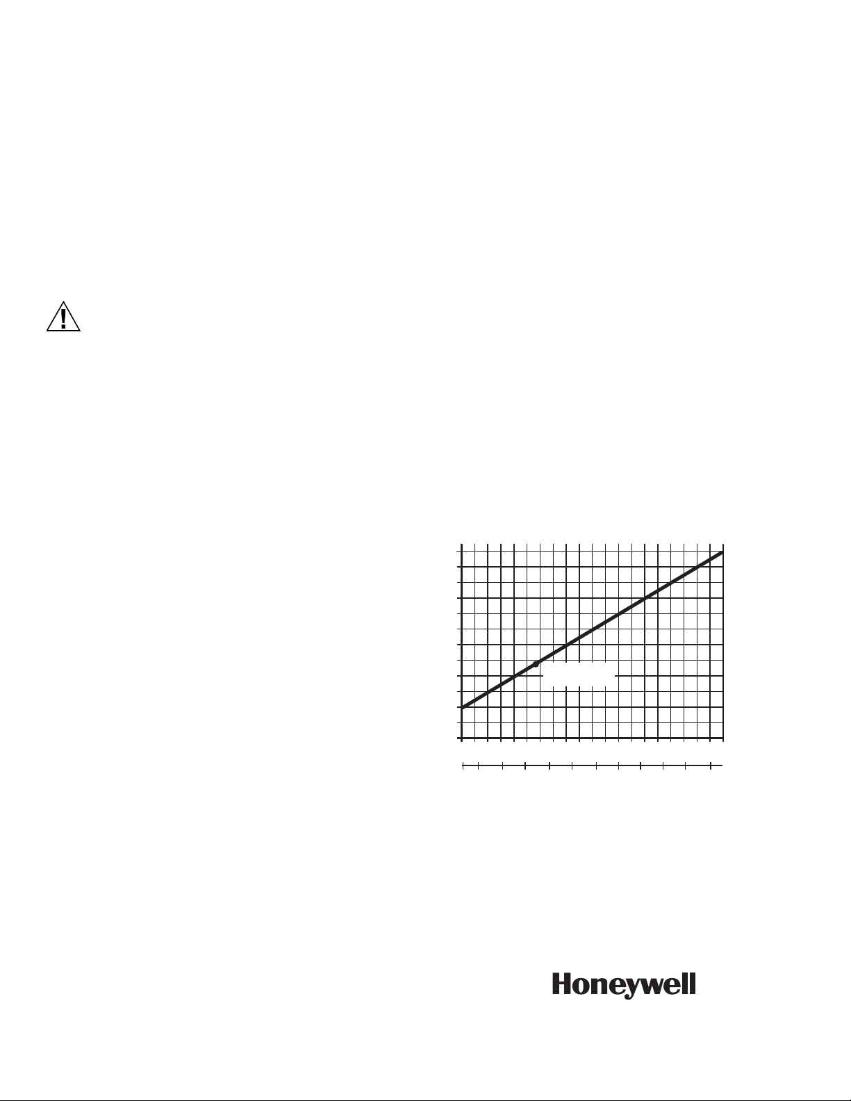
TEMPERATURE SENSOR RESISTANCE:
(see Fig. 3)
Temperature °C -10 0 10 20 30 40
Temperature °F 14 32 50 68 86 104
APPLICATION
The SP3000 Temperature Sensors are for use with
electronic controllers where linear PTC sensors are
required (T7075, Series 1000, W7100, W7600, W7620,
R7380J,L) in immersion or strap-mounted discharge
applications.
FEATURES
• Requires no settings or calibration.
• Platinum positive temperature coefficient (PTC)
sensing element.
• Resistance range is 2900 to 4400 ohms.
• Suitable for mounting in immersion well.
• Can be strapmounted to discharge pipe of boiler or
chiller.
Resistance in
ohms—SP3000
SENSING ACCURACY: +/-2° F [1.1° C].
AMBIENT TEMPERATURE RANGES:
Operating and Shipping:
For SP3000-2 and SP3000-15: -40 to +302° F
(-40 to +150° C)
For SP3000-WR: -40 to +248° F (-40 to +120° C)
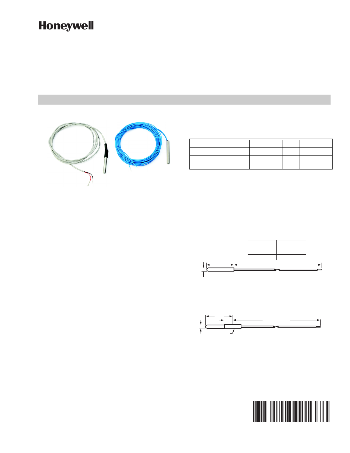
DIMENSIONS: See Fig. 1 and 2.
Ø1/4 (6)
2 (51)
Fig. 1. Approximate dimensions of SP3000-2 and
SP3000-15 Encapsulated Temperature Sensor in in.
3,178 3,266 3,353 3,440 3,527 3,613
ITEM NUMBER
TABLE A
SP3000-2
SP3000-15
SEE TABLE A
(mm).
PRODUCT DATA
LEAD LENGTH
INCHES (MM)
24 (610)
180 (4572)
M37069
SPECIFICATIONS
IMPORTANT:
The specifications given in this publication do not
include normal manufacturing tolerances. Therefore, an individual unit may not exactly match the
listed specifications. Also, this product is tested
and calibrated under closely controlled conditions
and some minor differences in performance can
be expected if those conditions are changed.
Fig. 2. Approximate dimensions of SP3000-WR
Encapsulated Temperature Sensor in in. (mm).
Page 2
SP3000, PT3000 SENSORS
CAUTION
RESISTANCE
(OHMS)
4200
4000
3800
3600
3400
3200
20 40
60
80 100 120
140 160
180 200 220
-7
0
10
20 30
40 50
60
70 80 90
100
F
C
3484 ± 6.5 OHMS
AT 77¡F (25¡C)
M2829A
TEMPERATURE (DEGREES)
INSTALLATION
When Installing This Product…
1. Read these instructions carefully. Failure to follow
them could damage the product or cause a hazardous condition.
2. Check the ratings given in the instructions and on
the product to make sure the product is suitable for
your application.
3. Installer must be a trained, experienced service
technician.
4. After installation is complete, check out product
operation as provided in these instructions.
Disconnect power supply before making wiring
connections to prevent electrical shock or
equipment damage.
Location and Mounting
The SP3000 Encapsulated Temperature Sensor can be
installed by strapping the sensor to the outside of a boiler
or chiller output pipe, or by placing the sensor in the fluid
of a boiler or chiller using an immersion well. Instructions
for both types of installations follow.
Strapping The SP3000 To A Boiler Or
Chiller Output Pipe
Some applications require that the sensor be strapped to
the outside of a pipe. Strap-on mounting avoids the need
for an immersion well and pipe fittings, and also
eliminates the system draining, refilling, and bleeding
necessary to install the immersion well.
2. Clean the pipe surface for good sensor-to-pipe con-
tact. Apply heat conductive compound to the pipe at
the selected location.
3. Press the sensor bulb into the heat conductive com-
pound and fasten to the discharge pipe with 105900
Pipe Clamp, duct hanger wire or with metal hose
clamps.
IMPORTANT:
Erratic temperature readings from a sensor can be
caused by the wiring practices described below.
These must be avoided to assure proper operation.
Use shielded cable to reduce interference if
rerouting of sensor wiring is not possible.
1. Do not route temperature sensor wiring with building power wiring, next to control contactors or near
light dimming circuits, electric motors or welding
equipment.
2. Avoid poor wiring connections.
3. Avoid intermittent or missing building earth
ground. Do not mount sensor in incorrect environment.
Resistance in the SP3000 Sensor wiring positively offsets
the temperature sensed by 1 degree F for every 4.8 ohms
[8.6 ohms/°C] of resistance. Use larger gauge wire when
longer lengths are necessary.
OPERATION AND CHECKOUT
External mounting of the sensor produces a slight offset
in the temperature control point. The control temperature
could be increased up to 5° F [2.8° C] with a bare sensor
strapped to the discharge pipe. Use a heat conductive
compound and apply insulation around the SP3000 and
pipe to decrease the temperature offset. Obtain any
necessary straps, clamps and insulation locally.
The sensor bulb should be located at a point on the
discharge pipe approximately 3 ft [1 m] from the boiler or
chiller.
1. Remove any insulation on the pipe, leaving about 6
Home and Building Technologies
In the U.S.:
Honeywell
715 Peachtree Street NE
Atlanta, GA 30308
customer.honeywell.com
in. [15 cm] of the pipe exposed. With care, most insulating materials may be able to be reused to cover
the sensor when the installation is complete.
By using this Honeywell literature, you agree that Honeywell will have no liability for any damages arising out of your use or
modification to, the literature. You will defend and indemnify Honeywell, its affiliates and subsidiaries, from and against any
liability, cost, or damages, including attorneys’ fees, arising out of, or resulting from, any modification to the literature by you.
® U.S. Registered Trademark
© 2020 Honeywell International Inc.
31-00132—02 M.S. Rev. 04-20
Printed in United States
Fig. 3. SP3000 temperature/resistance curve.
 Loading...