

Page 1
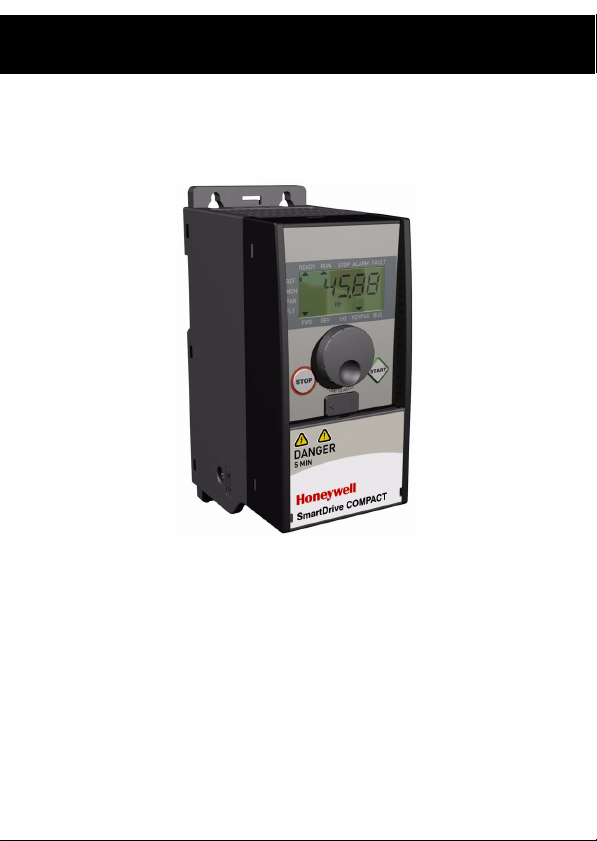
Ho
Honeywell
Complete User Manual
SmartDrive Compact
Constan and variable torque
Variable Frequency Drives
for Induction motors
Subject to changes without notice
Page 2

Honeywell 1
User’s Manual
Index
1. SAFETY ..........................................................................................3
1.1 Warnings ................................................................................3
1.2 Safety instructions .................................................................. 5
1.3 Grounding and earth fault protection......................................5
1.4 Before running the motor........................................................6
2. RECEIPT OF DELIVERY ................................................................ 7
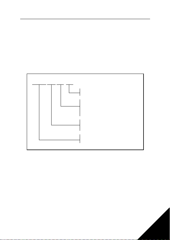
2.1 Type designation code ........................................................... 7
2.2 Storage................................................................................... 7
2.3 Maintenance........................................................................... 7
2.4 Warranty................................................................................. 8
3. INSTALLATION ..............................................................................9
3.1 Mechanical installation ........................................................... 9
3.1.1 SmartDrive Compact dimensions ................................10
3.1.2 Cooling......................................................................... 10
3.1.3 EMC-levels...................................................................11
3.1.4 Changing the EMC protection class.............................12
3.2 Cabling and connections ........................................................13
3.2.1 Power cabling .............................................................. 13
3.2.2 Control cabling .............................................................14
3.2.3 Cable and fuse specifications ...................................... 16
3.2.4 General cabling rules ...................................................17
3.2.5 Stripping lengths of motor and mains cables...............18
3.2.6 Cable installation and the UL standards ......................18
3.2.7 Cable and motor insulation checks ..............................19
4. COMMISSIONING........................................................................... 20
4.1 Commissioning steps of SmartDrive Compact....................... 20
5. FAULT TRACING ........................................................................... 22
6. SMARTDRIVE COMPACT CONTROL CONNECTIONS ...............25
6.1 Introduction.............................................................................25
6.2 Control I/O ..............................................................................26
7. CONTROL PANEL..........................................................................27
7.1 General...................................................................................27
7.2 Display....................................................................................27
7.3 Keypad ...................................................................................28
7.4 Navigation on the SmartDrive Compact control panel ...........29
7.4.1 Main menu ...................................................................29
7.4.2 Reference menu .......................................................... 30
7.4.3 Monitoring menu ..........................................................30
Page 3

2 Honeywell
7.4.4 Parameter menu...........................................................32
7.4.5 Fault history menu ........................................................33
8. PARAMETERS................................................................................34
8.1 Quick setup parameters (Virtual menu, shows when par. 3.1 = 1)
..............................................................................................35
8.2 Motor settings (Control panel: Menu PAR -> P1) ...................37
8.3 Start/stop setup (Control panel: Menu PAR -> P2).................38
8.4 Frequency references (Control panel: Menu PAR -> P3).......38
8.5 Ramps and brakes setup (Control panel: Menu PAR -> P4)..39
8.6 Digital inputs (Control panel: Menu PAR -> P5) .....................39
8.7 Analogue inputs (Control panel: Menu PAR -> P6)................40
8.8 Digital and analogue outputs (Control panel: Menu PAR -> P7)
..............................................................................................41
8.9 Protections (Control panel: Menu PAR -> P9)........................42
8.10 Autorestart parameters (Control panel: Menu PAR -> P10).42
8.11 PI control parameters (Control panel: Menu PAR -> P12) ...43
8.12 Easy usage menu (Control panel: Menu PAR -> P0)..........44
8.13 System parameters ..............................................................44
9. PARAMETER DESCRIPTIONS ......................................................46
9.1 Motor settings (Control panel: Menu PAR -> P1) ...................46
9.2 Start/Stop setup (Control panel: Menu PAR -> P2)................50
9.3 Frequency references (Control panel: Menu PAR -> P3).......53
9.4 Ramps & brakes setup (Control panel: Menu PAR -> P4) .....54
9.5 Digital inputs (Control panel: Menu PAR -> P5) .....................58
9.6 Analoque inputs (Control panel: Menu PAR -> P6)................59
9.7 Digital and analoque outputs (Control panel: Menu PAR -> P7)
..............................................................................................59
9.8 Motor thermal protection (parameters 9.7 - 9.10)...................60
9.9 Autorestart parameters (Control panel: Menu PAR -> P10)..63
9.10 PI control parameters (Control panel: Menu PAR -> P12) ...63
9.11 Easy usage menu (Control panel: Menu PAR -> P9)...........65
9.12 Fieldbus parameters (Control panel: Menu PAR -> S2).......66
9.12.1 Modbus process data .................................................67
10. TECHNICAL DATA .......................................................................70
10.1 SmartDrive Compact technical data .....................................70
10.2 Power ratings........................................................................72
10.2.1 SmartDrive Compact - Mains voltage 208 - 240 V.....72
10.2.2 SmartDrive Compact - Mains voltage 380 - 480 V.....73
Page 4
Honeywell Safety 3
ONLY A COMPETENT ELECTRICIAN IS ALLOWED TO
CARRY OUT THE ELECTRICAL INSTALLATION!
1. SAFETY
This manual contains clearly marked cautions and warnings which are intended for
your personal safety and to avoid any unintentional damage to the product or connected appliances.
Please read the information included in cautions and warnings carefully:
= Dangerous voltage
Risk of death or severe injury
= General warning
Risk of damage to the product or connected appliances
1.1 WARNINGS
The components of the power unit of the inverter are live when
SmartDrive Compact is connected to mains potential. Coming into
contact with this voltage is extremely dangerous and may cause
1
death or severe injury. The control unit is isolated from the mains
potential.
The motor terminals U, V, W (T1, T2, T3) and the possible brake
resistor terminals -/+ are live when inverter is connected to mains,
2
even if the motor is not running.
The control I/O-terminals are isolated from the mains potential.
However, the relay output terminals may have a dangerous control
3
voltage present even when inverter is disconnected from mains.
The earth leakage current of SmartDrive Compact inverters
exceeds 3.5mA AC. According to standard EN61800-5-1, a rein-
4
forced protective ground connection must be ensured.
If the inverter is used as a part of a machine, the machine manufacturer is responsible for providing the machine with a main
5
switch (EN 60204-1).
1
Page 5
1
4 Safety Honeywell
If SmartDrive Compact is disconnected from mains while running
the motor, it remains live if the motor is energized by the process.
In this case the motor functions as a generator feeding energy to
6
the inverter.
After disconnecting the inverter from the mains, wait until the fan
stops and the indicators on the display go out. Wait 5 more min-
7
utes before doing any work on power connections.
Page 6
Honeywell Safety 5
1.2 SAFETY INSTRUCTIONS
The SmartDrive Compact inverter has been designed for fixed
1
installations only.
Do not perform any measurements when the inverter is connected
2
to the mains.
Do not perform any voltage withstand tests on any part of Smart-
3
Drive Compact. The product safety is fully tested at factory.
Prior to measurements on the motor or the motor cable, disconnect
4
the motor cable from the inverter.
Do not open the cover of SmartDrive Compact. Static voltage discharge from your fingers may damage the components. Opening
5
the cover may also damage the device. If the cover of SmartDrive
Compact is opened, warranty becomes void.
1.3 GROUNDING AND EARTH FAULT PROTECTION
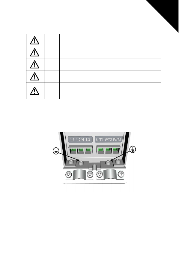
The SmartDrive Compact inverter must always be earthed with an grounding conductor connected to the grounding terminal. See figure below:
1
• The earth fault protection inside the inverter protects only the con-
verter itself against earth faults.
• If fault current protective switches are used they must be tested
with the drive with earth fault currents that are possible to arise in
fault situations.
Page 7
1
6 Safety Honeywell
1.4 BEFORE RUNNING THE MOTOR
Checklist:
Before starting the motor, check that the motor is mounted
properly and ensure that the machine connected to the motor
allows the motor to be started.
Set the maximum motor speed (frequency) according to the
motor and the machine connected to it.
Before reversing the motor shaft rotation direction make sure
that this can be done safely.
Make sure that no power correction capacitors are connected
to the motor cable.
Page 8
Honeywell Receipt of Delivery 7
COMP400-1P1-20
Product range:
COMP = SmartDrive Compact
Nominal voltage:
230 = 208-240 Vac (1~ input, 3~ output)
400 = 380-500 Vac
Nominal power:
P75 = 0.75 kW
1P1 = 1.1 kW
Etc.
Enclosure class:
20 = IP20
COMP400-1P1-20
Product range:
COMP = SmartDrive Compact
Nominal voltage:
230 = 208-240 Vac (1~ input, 3~ output)
400 = 380-500 Vac
Nominal power:
P75 = 0.75 kW
1P1 = 1.1 kW
Etc.
Enclosure class:
20 = IP20
2. RECEIPT OF DELIVERY
After unpacking the product, check that no signs of transport damages are to be
found on the product and that the delivery is complete (compare the type designation
of the product to the code below).
Should the drive have been damaged during the shipping, please contact primarily
the cargo insurance company or the carrier.
If the delivery does not correspond to your order, contact the supplier immediately.
2.1 TYPE DESIGNATION CODE
Figure 2.1: SmartDrive Compact type designation code
2.2 STORAGE
If the inverter is to be kept in store before use make sure that the ambient conditions
are acceptable:
Storing temperature-40…+70°C
Relative humidity < 95%, no condensation
2.3 MAINTENANCE
In normal operating conditions, SmartDrive Compact inverters are maintenancefree.
2
Page 9

8 Receipt of Delivery Honeywell
2.4 WARRANTY
Honeywell’s time of warranty is 30 months from the delivery or 24 months from the
commissioning whichever expires first (General Conditions NL92/Orgalime S92 ).
2
Page 10
Honeywell Installation 9
MI2-3MI1
=M 4
=M 5
12
3. INSTALLATION
3.1 MECHANICAL INSTALLATION
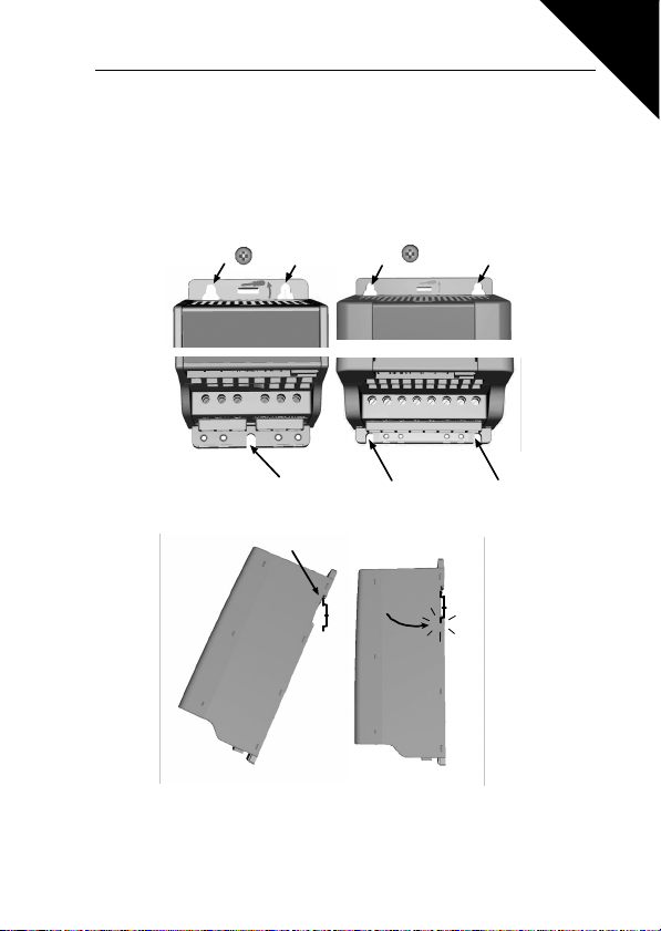
There are two possible ways to mount SmartDrive Compact in the wall; either screw
or DIN-rail mounting. The mounting dimensions are given on the back of the drive
and on the following page.
Figure 3.1: Screw mounting
3
Figure 3.2: DIN-rail mounting
Page 11

3
W1
W2
W3
H1
H2D1H3
D2
10 Installation Honeywell
3.1.1 SmartDrive Compact dimensions
Figure 3.3: SmartDrive Compact dimensions, MI1-MI3
Typ e H1 H2 H3 W1 W2 W3 D1 D2
MI1 156,5 147 137,3 65,5 37,8 4,5 98,5 7
MI2 195 183 170 90 62,5 5,5 101,5 7
MI3 262,5 252,3 241,3 100 75 5,5 108,5 7
Table 3.1 : SmartDrive Compact dimensions in millimetres
3.1.2 Cooling
Forced air flow cooling is used in all SmartDrive Compact drives.
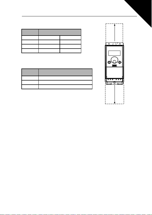
Enough free space shall be left above and below the inverter to ensure sufficient air
circulation and cooling. You will find the required dimensions for free space in the table below:
Page 12
Honeywell Installation 11
A
B
Typ e Dimensions (mm)
AB
MI1 100 50
MI2 100 50
MI3 100 50
Table 3.2 : Dimensions required for cooling
3
Typ e
MI1 10
MI2 10
MI3 30
Table 3.3 : Required cooling air
Note! Side-to-side installation allowed only if the ambient temperature is below 40
degrees Celsius.
Cooling air required (m3/h)
3.1.3 EMC-levels
SmartDrive Compact inverters are divided into three classes according to the level
of electromagnetic disturbances emitted, the requirements of a power system network and the installation environment (see below). The EMC class of each product
is defined in the type designation code.
Category C1 (Honeywell EMC class C): Inverters of this class comply with the requirements of category C1 of the product standard EN 61800-3 (2004). Category C1
ensures the best EMC characteristics and it includes converters the rated voltage of
which is less than 1000V and which are intended for use in the 1st environment. This
EMC class is meant for highly sensitive areas and can be sometimes required in installations in e.g. hospitals or airport control towers.
NOTE: The requirements of class C1 are fulfilled only as far as the conducted emissions are concerned with an external EMC-filter.
Category C2 (Honeywell EMC class H): All Honeywell SmartDrive Compact inverters comply with the requirements of category C2 of the product standard EN 618003 (2004). Category C2 includes converters in fixed installations and the rated voltage
of which is less than 1000V. The class H inverters can be used both in the 1st and
the 2nd environment. This category fulfills the requirements with normal installations
in buildings.
Page 13
3
12 Installation Honeywell
IT networks (Honeywell EMC class T): Inverters of this class fulfil the product
standard EN 61800-3 (2004) if intended to be used in IT systems. In IT systems, the
networks are isolated from earth, or connected to earth through high impedance to
achieve a low leakage current. NOTE: if inverters are used with other supplies, no
EMC requirements are complied with. SmartDrive Compact inverters can be easily
modified to the requirements of the T-class. This class is very typical requirement
also in installations in ships.
Environments in product standard EN 61800-3 (2004)
First environment: Environment that includes domestic premises. It also includes
establishments directly connect ed without intermediate transformers to a low-voltage
power supply network which supplies buildings used for domestic purposes.
NOTE: houses, apartments, commercial premises or offices in a residential building
are examples of first environment locations.
Second environment: Environment that includes all establishments other than
those directly connected to a low-voltage power supply network which supplies buildings used for domestic purposes.
NOTE: industrial areas, technical areas of any building fed from a dedicated transformer are examples of second environment locations.
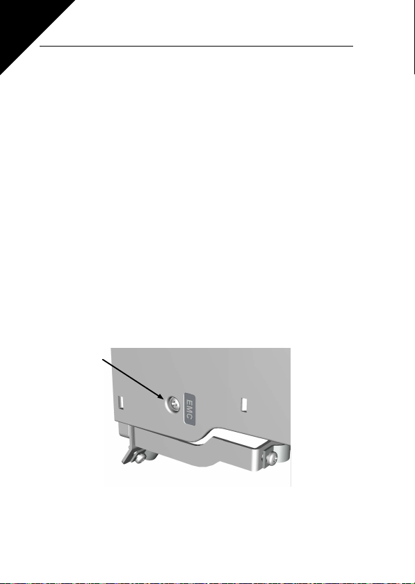
3.1.4 Changing the EMC protection class
The EMC protection class of SmartDrive Compact inverters can be changed from
class H by removing the EMC-capacitor disconnecting screw, see figure below.
Note! Do not attempt to change the EMC level back to class H. Even if the proce-
dure above is reversed, the inverter will no longer fulfil the EMC requirements of
class H!
Page 14
Honeywell Installation 13
3.2 CABLING AND CONNECTIONS
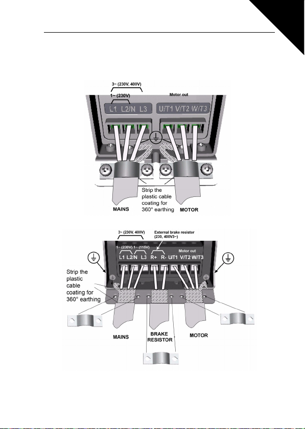
3.2.1 Power cabling
Note! Tightening torque for power cables is 0.5 - 0.6 Nm
Figure 3.4: SmartDrive Compact power connections, MI1
3
Figure 3.5: SmartDrive Compact power connections, MI2 - MI3
Page 15

3
14 Installation Honeywell
3.2.2 Control cabling
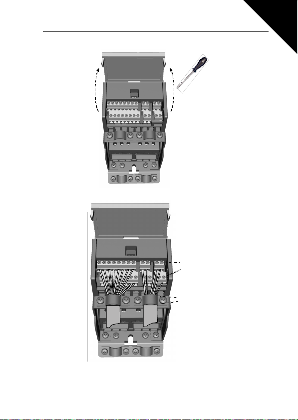
Figure 3.6: Mount the PE- plate and control cable support
Page 16
Honeywell Installation 15
Strip the p lastic
cable coating for
360
°
Control cable
tightening
torque: 0.4 Nm
grounding
Figure 3.7: Open the cover
3
Figure 3.8: Install the control cables. See Chapter 6.2
Page 17
3
16 Installation Honeywell
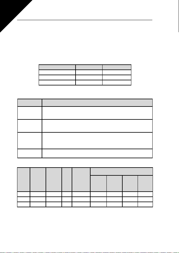
3.2.3 Cable and fuse specifications
Use cables with heat resistance of at least +70 C. The cables and the fuses must be
dimensioned according to the tables below. Installation of cables according to UL
regulations is presented in Chapter 3.2.6.
The fuses function also as cable overload protection.
These instructions apply only to cases with one motor and one cable connection from
the inverter to the motor. In any other case, ask the factory for more information.
EMC class Level H (C2) Level C (C1)
Mains cable types 1 1
Motor cable types 3 3
Control cable types 4 4
Table 3.4 : Cable types required to meet standards. EMC levels are
described in Chapter 3.1.3.
Cable type Description
Power cable intended for fixed installation and the specific mains voltage.
Shielded cable not required.
1
(NKCABLES/MCMK or similar recommended)
Power cable equipped with concentric protection wire and intended for the
specific mains voltage.
2
(NKCABLES /MCMK or similar recommended).
Power cable equipped with compact low-impedance shield and intended
for the specific mains voltage.
3
(NKCABLES /MCCMK, SAB/ÖZCUY-J or similar recommended).
*360º grounding of both motor and FC connection r equired to meet the standard
Screened cable equipped with compact low-impedance shield (NKCA-
4
Table 3.5 : Cable type descriptions
BLES /Jamak, SAB/ÖZCuY-O or similar).
Fuse
[A]
Mains
cable
Cu [mm2]
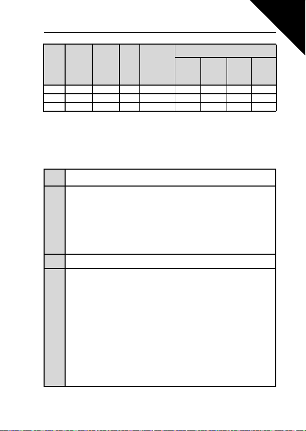
I
Frame Type
MI1 P25-P75 1.7-3.7 10 2*1.5+1.5 1.5-4 1.5-4 0.5-1.5 0.5-1.5
MI2 1P1-1P5 4.8-7.0 20 2*2.5+2.5 1.5-4 1.5-4 0.5-1.5 0.5-1.5
MI3 2P2 9.6 32 2*6+6 1.5-6 1.5-6 0.5-1.5 0.5-1.5
[A]
N
Terminal cable size (min/max)
Main
Earth
terminal
2
[mm
]
Control
terminal
2
[mm
]
terminal
2
[mm
]
Table 3.6 : Cable and fuse sizes for SmartDrive Compact, 208 - 240V
Relay
terminal
2
[mm
]
Page 18
Honeywell Installation 17
3
Terminal cable size (min/max)
Main
Earth
terminal
2
[mm
]
Control
terminal
2
[mm
]
terminal
2
[mm
]
Relay
terminal
[mm
Fuse
[A]
Mains
cable
Cu [mm2]
I
Frame Ty pe
MI1 P37-1P1 1.9-3.3 6 3*1.5+1.5 1.5-4 1.5-4 0.5-1.5 0.5-1.5
MI2 1P5-2P2 4.3-5.6 10 3*1.5+1.5 1.5-4 1.5-4 0.5-1.5 0.5-1.5
MI3 3P0-5P5 7.6-12 20 3*2.5+2.5 1.5-6 1.5-6 0.5-1.5 0.5-1.5
[A]
N
Table 3.7 : Cable and fuse sizes for SmartDrive Compact, 380 - 480V
Note! To fulfil standard EN61800-5-1, the protective conductor should be at least
10mm2 Cu or 16mm Al. Another possibility is to use an additional protective con-
ductor of at least the same size as the original one.
3.2.4 General cabling rules
Before starting the installation, check that none of the components of the inverter
1
is live.
Place the motor cables sufficiently far from other cables:
• Avoid placing the motor cables in long parallel lines with other cables
• If the motor cable runs in parallel with other cables, the minimum distance
between the motor cable and other cables is
2
3
4
0,3 m.
• The given distance also applies between the motor cables and signal cables
of other systems.
• The maximum length of the motor cables is 30 m
• The motor cables should cross other cables at an angle of 90 degrees.
If cable insulation checks are needed, see Chapter 3.2.7.
Connecting the cables:
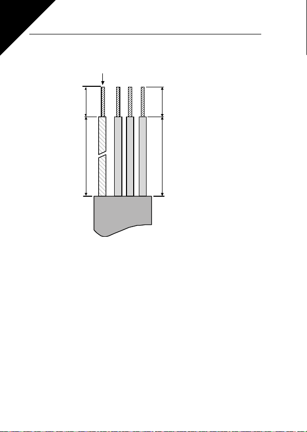
• Strip the motor and mains cables as advised in Figure 3.9.
• Connect the mains, motor and control cables into their respective terminals,
see Figures 3.4 - 3.8.
• Note the tightening torques of power cables and control cables given in
page 13 and page 15.
• For information on cable installation according to UL regulations see Chapter
3.2.6 .
• Make sure that the control cable wires do not come in contact with the electronic components of the unit
• If an external brake resistor (option) is used, connect its cable to the appropriate terminal.
• Check the connection of the earth cable to the motor and the inverter terminals marked with
• Connect the separate shield of the motor cable to the earth plate of the
inverter, motor and the supply centre
2
]
Page 19
3
20 mm
35 mm
8 mm
Earth conduct or
8 mm
18 Installation Honeywell
3.2.5 Stripping lengths of motor and mains cables
Figure 3.9: Stripping of cables
Note! Strip also the plastic cover of the cables for 360 degree grounding. See Figures 3.4, 3.5 and 3.8.
3.2.6 Cable installation and the UL standards
To meet the UL (Underwriters Laboratories) regulations, a UL-approved copper cable with a minimum heat-resistance of +60/75 0C must be used.
Page 20

Honeywell Installation 19
3.2.7 Cable and motor insulation checks
These checks can be performed as follows if motor or cable insulations are suspected to be faulty.
1. Motor cable insulation checks
Disconnect the motor cable from terminals U/T1, V/T2 and W/T3 of the inverter and
from the motor. Measure the insulation resistance of the motor cable between each
phase conductor as well as between each phase conductor and the protective
ground conductor.
The insulation resistance must be >1MOhm.
2. Mains cable insulation checks
Disconnect the mains cable from terminals L1, L2/N and L3 of the inverter and from
the mains. Measure the insulation resistance of the mains cable between each phase
conductor as well as between each phase conductor and the protective ground conductor.The insulation resistance must be >1MOhm.
3. Motor insulation checks
Disconnect the motor cable from the motor and open the bridging connections in the
motor connection box. Measure the insulation resistance of each motor winding. The
measurement voltage must equal at least the motor nominal voltage but not exceed
1000 V. The insulation resistance must be >1MOhm.
3
Page 21
20 Commissioning Honeywell
4. COMMISSIONING
Before commissioning, note the warnings and instructions listed in
Chapter 1!
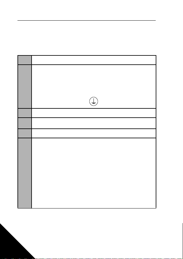
4.1 COMMISSIONING STEPS OF SMARTDRIVE COMPACT
Read carefully the safety instructions in Chapter 1 and follow them.
1
After the installation, make sure that:
• both the inverter and the motor are grounded
• the mains and motor cables comply with the requirements given in Chapter
3.2.3.
2
3
4
5
6
• the control cables are located as far as possible from the power cables
(see Chapter, step 2) and the shields of the shielded cables are connected
to protective earth.
Check the quality and quantity of cooling air (Chapter 3.1.2).
Check that all Start/Stop switches connected to the I/O terminals are in Stop-
position.
Connect the inverter to mains.
Run the Start Up Wizard (The Wizard is explained fully in chapter 9.11)
1. Activate the wizard by pressing STOP for 5 seconds
2. Tune the motor nominal speed
3. Tune the motor nominal current
4. Select the mode (0 = basic, 1 = Fan, 2 = Pump, 3 = Conveyor)
Or if the setting is done manually set the parameters of group 1 according to the
requirements of your application. At least the following parameters should be set:
• motor nominal voltage (par. 1.1)
• motor nominal frequency (par. 1.2)
• motor nominal speed (par. 1.3)
• motor nominal current (par. 1.4)
You will find the values needed for the parameters on the motor rating plate.
4
Page 22

Honeywell Commissioning 21
Perform test run without motor. Perform either Test A or Test B:
A) Control from the I/O terminals:
• Turn the Start/Stop switch to ON position.
• Change the frequency reference (potentiometer).
• Check in the Monitoring Menu that the value of Output frequency changes
according to the change of frequency reference.
• Turn the Start/Stop switch to OFF position.
7
B) Control from the keypad:
• Move to keypad control by pressing the navigation wheel for 5 seconds.
You can also select the keypad as the control place with par. 2.1.
• Push the Start button on the keypad.
• Check in the Monitoring Menu that the value of Output frequency changes
according to the change of frequency reference.
• Push the Stop button on the keypad.
Run the no-load tests without the motor being connected to the process, if possible. If this is not possible, secure the safety of each test prior to running it. Inform
your co-workers of the tests.
• Switch off the supply voltage and wait up until the drive has stopped.
• Connect the motor cable to the motor and to the motor cable terminals of
8
9
the inverter.
• See to that all Start/Stop switches are in Stop positions.
• Switch the mains ON.
• Repeat test 7A or 7B.
Connect the motor to the process (if the no-load test was run without the motor
being connected).
• Before running the tests, make sure that this can be done safely.
• Inform your co-workers of the tests.
• Repeat test 7A or 7B.
4
Page 23

5
F1 02
Fault code (02 = overvoltage)
Fault ordinal number (F1 = latest fault)
22 Fault Tracing Honeywell
5. FAULT TRACING
When a fault is detected by the inverter control electronics, the drive is stopped and
the symbol F together with the ordinal number of the fault and the fault code appear
on the display in the following format, e.g:
The fault can be reset by pressing the Stop button on the control keypad or via the I/
O terminal or fieldbus. The faults with time labels are stored in the Fault history menu
which can be browsed. The different fault codes, their causes and correcting actions
are presented in the table below.:
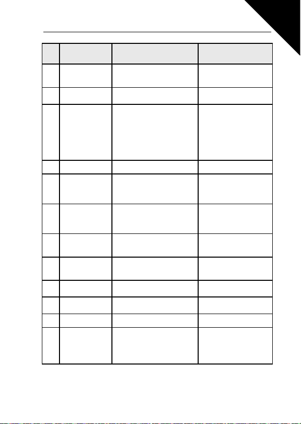
Fault
Fault name Possible cause Correcting actions
code
Overcurrent
1
Overvoltage
2
Earth fault
3
System fault
8
Undervoltage
9
Table 5.1 : Fault codes
Inverter has detected too high a
current (>4*I
The DC-link voltage has
exceeded the internal safety limit:
Current measurement has
detected extra leakage current at
start:
The DC-link voltage has
exceeded the internal safety limit:
) in the motor cable:
N
• Sudden heavy load increase
• Short circuit in motor cables
• Unsuitable motor
• Too short a deceleration time
• High overvoltage spikes in
mains
• Insulation failure in cables or
motor
• Component failure
• Faulty operation
• Most probable cause: too low
a supply voltage
• Inverter internal fault
• Power outages
Check loading.
Check motor size.
Check cables.
Increase the deceleration
time (P.4.3).
Check motor cables and
motor.
Reset the fault and restart.
Should the fault recur, contact technical support.
In case of temporary supply
voltage break reset the fault
and restart the inverter.
Check the supply voltage. If
it is adequate, an internal
failure has occurred.
Contact technical support.
Page 24
Honeywell Fau lt Tra cin g 23
Fault
Fault name Possible cause Correcting actions
code
Output phase
11
supervision
Inverter undertem-
13
perature
Inverter overtem-
14
perature
Motor stalled Motor stall protection has tripped Check motor.
15
Motor overtempera-
16
ture
Motor Underload
17
EEPROM check-
22
sum fault
Microcontroller
25
watchdog fault
Back EMF
27
protection
Internal bus com-
34
munication
Application fault Application does not function Contact technical support.
35
Analogue input Iin
< 4mA (selected
50
signal range 4 to 20
mA)
Table 5.1 : Fault codes
Current measurement has
detected that there is no current
in one motor phase
IGBT switch temperature is under
0
-10
C
IGBT switch temperature is over
120 C. Overtemperature warning
is issued when the IGBT switch
temperature exceeds 110
Motor overheating has been
detected by inverter motor temperature model. Motor is overloaded
Motor underload protection has
detected a low load situation
Parameter save fault
• Faulty operation
• Component failure
• Faulty operation
• Component failure
Ambient interference or defective
hardware
Current at the analogue input is
< 4mA
• Control cable is broken or
loose
• Signal source has failed
0
C
Check motor cable and
motor.
Check the ambient temperature.
Check that the cooling air
flow is not blocked.
Check the ambient temperature.
Make sure that the switching
frequency is not too high in
relation to ambient temperature and motor load.
Decrease the motor load.
If no motor overload exists,
check the temperature
model parameters.
FAN: check that belt is not
broken.
PUMP: check that pump is
not dry.
Contact technical support.
Reset the fault and restart.
Should the fault recur, contact technical support.
Should the fault recur, contact technical support.
Check the current loop
circuitry.
5
Page 25

5
24 Fault Tracing Honeywell
Fault
Fault name Possible cause Correcting actions
code
Digital input fault. Digital input
External fault
51
Fieldbus fault
53
Identification fault Identification run has failed
57
has been programmed as external fault input and this input is
active
The data connection between the
fieldbus Master and the fieldbus
of the drive broken
Table 5.1 : Fault codes
Check the programming and
the device indicated by the
external fault information.
Check also the cabling of
this device.
Check installation.
If installation is correct contact the nearest Honeywell
technical support.
Run command was
removed before completion
of identification run.
Motor is not connected to
inverter. There is load on
motor shaft.
Page 26
Honeywell Control connection s 25
6. SMARTDRIVE COMPACT CONTROL CONNECTIONS
6.1 INTRODUCTION
SmartDrive Compact is equipped with following control inputs and outputs:
Control I/O
6 Digital inputs
2 Analogue inputs
1 Analogue output
1 Digital output
2 Relay outputs
RS-485 Interface
Table 6.1: Control I/O connections in SmartDrive
This section provides you with a description and instructions of the I/O-signals.
The speed reference can be selected from the analogue inputs, fieldbus, preset
speeds or keypad.
Basic properties:
• Digital inputs DI1…DI6 are freely programmable. The user can
assign a single input to many functions
• Digital-, relay- and analogue outputs are freely programmable
Special features:
Compact
• Programmable Start/Stop and Reverse signal logic
• Reference scaling
• Programmable start and stop functions
• DC-brake at start and stop
• Programmable U/f curve
• Adjustable switching frequency
• Autorestart function after fault
• Protections and supervisions (all fully programmable; off, warning,
fault):
• Current signal input fault
• External fault
• Undervoltage fault Earth fault
• Motor thermal, stall and underload protection
• Fieldbus communication
• 8 preset speeds
• Ana logue input range se lecti on, sign al sca ling a nd
filtering
• PI-controller
6
Page 27
26 Control connections Honeywell
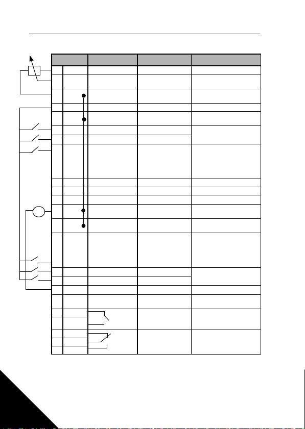
6.2 CONTROL I/O
Ter min al Signal Factory preset Description
+10Vre Ref. voltage out Maximum load 10 mA
1
AI1 Analog signal in 1
2
GND I/O signal ground
3
24Vout 24V output for DI's ± 20%, max. load 50 mA
6
GND I/O signal ground
7
DI1 Digital input 1
8
DI2 Digital input 2
9
DI3 Digital input 3
10
A RS485 signal A FB Communication Modbus
A
B RS485 signal B FB Communication Modbus
B
AI2 Analog signal in 2
4
GND I/O signal ground
5
mA
GND I/O signal ground
13
DI4 Digital input 4
14
DI5 Digital input 5
15
DI6 Digital input 6
16
AO
18
DO Digital signal out
20
Rel ay ou t 1
RO 13
22
RO 14
23
RO 22
24
25
26
Table 6.2: Default I/O configuration and connections
P) = Programmable function, see parameter lists and descriptions, chapters
8 and 9
RO 21
RO 24
Relay out 2
Freq. reference
Start forward
Start reverse
Preset speed B0
PI actual value
Preset speed B1
Fault reset
Disable PI contr.
Output frequency
Active = READY
Active = RUN
Active = FAULT
0 - +10 V Ri = 200 k
P)
(min)
Ground for reference and
controls
Ground for reference and
controls
P)
0 - +30 V Ri = 12 k
P)
0 - +30V Ri = 12 k
B0 active = Preset speed
P)
1 (default 10Hz)
B0 & B1 = Preset speed 3
(default 20 Hz)
P)
0(4) - 20 mA, Ri = 200
Ground for reference and
controls
Ground for reference and
controls
0 - +30V Ri = 12 k
minB1 active = Preset
P)
speed 2 (default 15Hz)
B0 & B1 = Preset speed 3
(default 20 Hz)
P)
0 - +30 V Ri = 12 k min
P)
P)
0(4) - 20 mA, RL = 500
Open collector, max. load
P)
48V/50mA
Max. switching load:
P)
250Vac/2A or 250Vdc/
0,4A
Max. switching load:
P)
250Vac/2A or 250Vdc/
0,4A
min
min
W
6
Page 28

Honeywell Control Panel 27
7. CONTROL PANEL
7.1 GENERAL
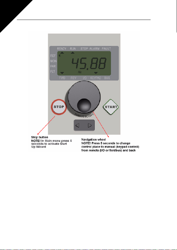
The panel is integrated to the drive consisting of corresponding application card and
an overlay on the drive cover with status display and button clarifications.
The Control panel consists of an LCD display with backlight and a keypad including
a navigation wheel, a green START button and a red STOP button (see Figure 7.1).
7.2 DISPLAY
The display includes 14-segment and 7-segment blocks, arrowheads and clear text
unit symbols. The arrowheads, when visible, indicate some information about the
drive, which is printed in clear text on the overlay (numbers 1…14 in the figure below). The arrowheads are grouped in 3 groups with the following meanings and English overlay texts (see Figure 7.1):
Group 1 - 5; Drive status
1 = Drive is ready to start (READY)
2 = Drive is running (RUN)
3 = Drive has stopped (STOP)
4 = Alarm condition is active (ALARM)
5 = Drive has stopped due to a fault (FAULT)
Group 6 - 10; Control selections
6 = Motor is rotating forward (FWD)
7 = Motor is rotating reverse (REV)
8 = I/O terminal block is the selected control place (I/O)
9 = Keypad is the selected control place (KEYPAD)
10 = Fieldbus is the selected control place (BUS)
Group 11 - 14; Navigation main menu
11 = Reference main menu (REF)
12 = Monitoring main menu (MON)
13 = Parameter main menu (PAR)
14 = Fault history main menu (FLT)
7
Page 29
7
28 Control Panel Honeywell
Figure 7.1: SmartDrive Compact Control panel
7.3 KEYPAD
The keypad section of the control panel consists of a navigation wheel and START
and STOP buttons (see Figure 7.1). The navigation wheel is used for navigating on
the panel display, but it also works as a reference potentiometer when KEYPAD has
been selected as the control place of the drive. The wheel has two separate functions;
- Rotating the wheel e.g. for changing parameter value (12 steps / round)
- Pressing the wheel e.g. for accepting the new value.
The drive stops always, regardless of the selected control place, by pressing the keypad STOP button. The drive starts by pressing the keypad START button, but only if
the selected control place is KEYPAD.
Page 30
Honeywell Control Panel 29
Hz Hz
FWD REV I/O KEYPAD BUS
REF
MON
PAR
FLT
FAULTALARMSTOPREADY RUN
FWD REV I/O KEYPAD B US
REF
PA R
FLT
FAULTALARMSTOPREADY RUN
MON
PUSH
FWD REV I/O KEYPAD BUS
REF
PAR
FLT
FAULTALARMSTOPREADY RUN
MON
FWD REV I/O KEYPAD BUS
REF
PAR
FLT
FAULTALARMSTOPREADY RUN
MON
PUSH
FWD REV I/O KEYPAD BUS
REF
PAR
FLT
FAULTALARMSTOPREADY RUN
MON
FWD REV I/O KEYPAD BUS
REF
PAR
FLT
FAULTALARMSTOPREAD Y RUN
MON
PUSH
FWD REV I/O KEYPAD BUS
REF
PAR
FLT
FAU LTALARMST OPREADY RUN
MON
ROTATE
ROTATE
ROTATE
REFERENCE
MENU
Displays the
keypad refere nce
value
regardless of
the selected
control place.
MONITORING
MENU
In thi s menu
you can
brow se the
monitoring
values.
PARAMETER
MENU
In this menu
you can
browse and
edit the
parameters.
FAULT MENU
Here you will
be able
to bro wse
through the
faults occurred.
PUSH
FWD REV I/O KEYPAD BUS
REF
MON
PAR
FLT
FAULTALARMSTOPREADY R UN
7.4 NAVIGATION ON THE SMARTDRIVE COMPACT CONTROL PANEL
This chapter provides you with information on navigating the menus on SmartDrive
Compact and editing the values of the parameters.
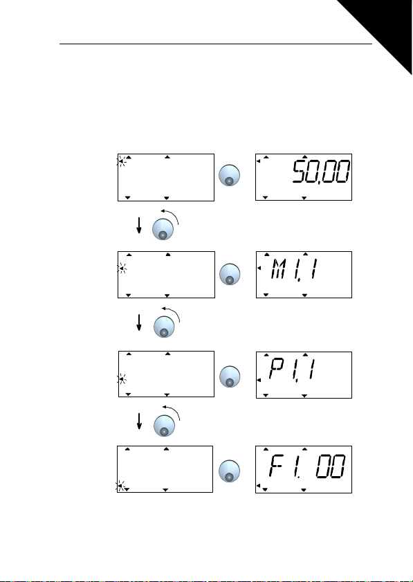
7.4.1 Main menu
The menu structure of SmartDrive Compact control software consists of a main
menu and several submenus. Navigation in the main menu is shown below:
7
Figure 7.2: The main menu of SmartDrive compact
Page 31
7
Hz
FAULTAL ARMSTOPREAD Y R UN
REF
MON
PA R
FLT
FWD REV I /O KE YPAD BUS
Push to enter
edit mode
Change
value
Push to
confirm
Hz
FAULTALAR MSTOPREADY RUN
REF
MON
PAR
FLT
FWD REV I /O KE YPAD BUS
Alternates
in the display
Browse
M1.1 - M1.20
30 Control Panel Honeywell
7.4.2 Reference menu
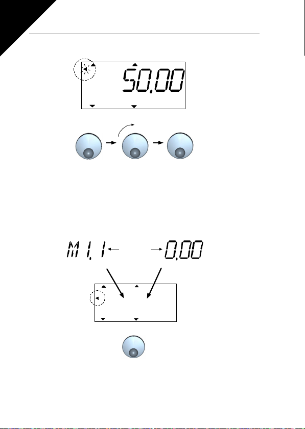
Figure 7.3: Reference menu display
Move to the reference menu with the navigation wheel (see Figure 7.2). The reference value can be changed with the navigation wheel as shown in Figure 7.3. The
reference value follows the rotation continuously (= without separate new value
acceptance) .
7.4.3 Monitoring menu
Figure 7.4: Monitoring menu display
Page 32
Honeywell Control Panel 31
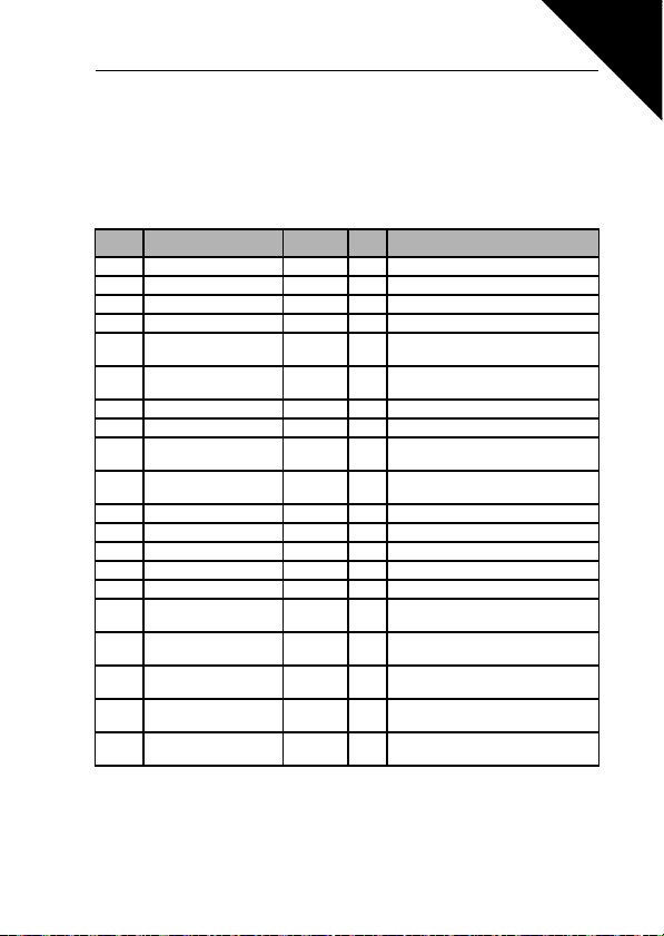
Monitoring values mean actual values of measured signals as well as statuses of
some control settings. They are visible in display, but they cannot be edited. The
monitoring values are listed in Table 7.1.
Pushing the navigation wheel once in this menu takes the user to the next level,
where the monitoring value, e.g. M1.11 and value are visible (see Figure 7.2). The
monitoring values can be browsed by rolling the navigation wheel clockwise, as
shown in Figure 7.4.
Code Monitoring signal Unit ID Description
M1.1 Output frequency Hz 1 Frequency to the motor
M1.2 Frequency reference Hz 25
M1.3 Motor shaft speed rpm 2 Calculated motor speed
M1.4 Motor current A 3 Measured motor current
M1.5 Motor torque % 4
M1.6 Motor power % 5
M1.7 Motor voltage V 6 Motor voltage
M1.8 DC-link voltage V 7 Measured DC-link voltage
M1.9 Unit temperature
M1.10 Motor temperature
M1.11 Analogue input 1 % 13 AI1 value
M1.12 Analogue input 2 % 14 AI2 value
M1.13 Analogue output % 26 AO1
M1.14 DI1, DI2, DI3 15 The status of digital inputs
M1.15 DI4, DI5, DI6 16 The status of digital inputs
M1.16 RO1, RO2, DO 17
M1.17 PI setpoint % 20
M1.18 PI feedback % 21
M1.19 PI error value % 22
M1.20 PI Output % 23
C
C
Table 7.1 : SmartDrive Compact monitoring signals
Calculated actual/nominal torque of
the motor
Calculated actual/nominal power of
the motor
8 Heat sink temperature
Calculated motor temperature
The statuse of Relays and digital
output
In percent of the maximum process
reference
In percent of the maximum actual
value
In percent of the maximum error
value
In percent of the maximum output
value
7
Page 33
7
Hz
FAU LTALARMST OPREADY RUN
REF
MON
PAR
FLT
FWD REV I/O KEYPAD BUS
Alternates
in the display
Browse
P1.1 ->
Push to enter
edit mode
Change
value
Push to
confirm
32 Control Panel Honeywell
7.4.4 Parameter menu
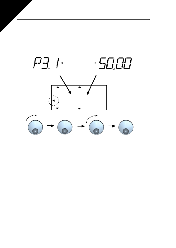
In Parameter menu only the Quick setup parameter list is shown by default. By giving
the right value to the parameter 13.1 it is possible to open other advanced parameter
groups. The parameter lists and descriptions can be found in chapters 8 and 9.
The following figure shows the parameter menu view:
Figure 7.5: Parameter menu
Page 34
Honeywell Control Panel 33
FAU LTALARMST OPREADY RUN
REF
MON
PAR
FLT
FWD REV I/O KEYPAD BUS
FAULTALARMSTOPRE ADY RUN
REF
MON
PAR
FLT
FWD REV I/O KEYPAD BUS
FAULTALARMSTOPREADY RUN
REF
MON
PAR
FLT
FWD REV I/O KEYPAD BUS
FAULTALARMSTOPREADY RUN
REF
MON
PAR
FLT
FWD REV I/O KEYPAD BUS
Browse
faults 1-9
Push
Push
Browse
for hours (H),
minutes (M)
and seconds (S)
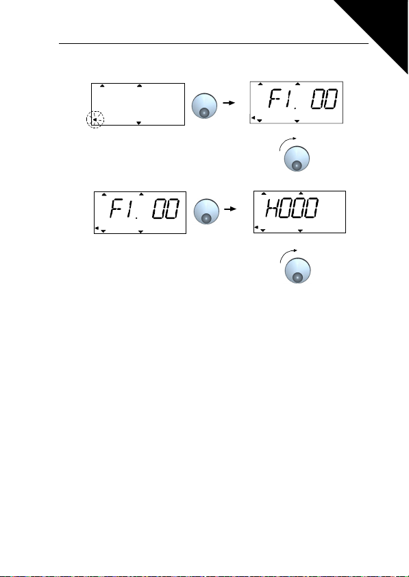
7.4.5 Fault history menu
Figure 7.6: Fault history menu
In Fault history menu you c an browse through 9 latest faults (see Figure 7 .6). If a fault
is active, the relevant fault number (e.g. F1 02) alternates in the display with main
menu. When you browse between the faults, the fault codes of active faults are blinking. The active faults can be reset by pressing the STOP button for 1 second. If the
fault cannot be reset, the blinking continues. It is possible to navigate in the menu
structure also when there are active faults present, but the display returns automatically to the fault menu if buttons or navigation wheel are not pressed or navigation is
not rotated. The operating hour, minute and second values at the fault instant are
shown in the value menu (operating hours = displayed reading x 1000 h).
Note! The whole fault history can be cleared by pressing STOP
button for 5 sec time when the drive is stopped and Fault history
See Chapter 5 in for fault descriptions.
menu is selected in the diisplay. When you are in main
menu pressing STOP button will start the Start Up
Wizard and return all parameter settings to
factory defaults.
7
Page 35

34 Par ameters Honeywell
8. PARAMETERS
On the next pages you can find the lists of parameters within the respective parameter groups. The parameter descriptions are given in Chapter 9.
NOTE: Parameters can only be changed when drive is in stop mode!
Explanations:
Code: Location indication on the keypad; Shows the operator the present
Parameter: Name of monitoring value or parameter
Min: Minimum value of parameter
Max: Maximum value of parameter
Unit: Unit of parameter value; given if available
Default: Factory preset value
ID: ID number of the parameter (used with fieldbus control)
Monitoring value number or Parameter number
More information on this paramet er available in chapter 9: ‘Parameter
descriptions’ click on the parameter name.
8
Page 36
Honeywell Parameters 35
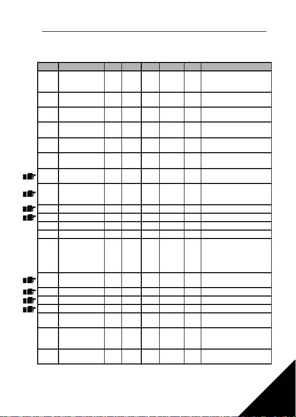
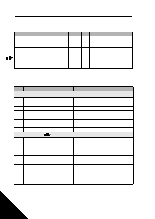
8.1 QUICK SETUP PARAMETERS (VIRTUAL MENU, SHOWS WHEN PAR.
3.1 = 1)
Code Parameter Min Max Unit Default ID Note
Motor nominal
P1.1
voltage
Motor nom. fre-
P1.2
quency
Motor nominal
P1.3
speed
Motor nominal
P1.4
current
P1.5
Motor cos
P1.7 Current limit
P1.15 Torque boost 0 1 0 109
P2.1 Control place 1 3 1 125
P2.2 Start function 0 1 0 505 0 = Ramp 1 = Flying start
P2.3 Stop function 0 1 0 506 0 = Coasting 1 = Ramp
P3.1 Min frequency 0,00 P3.2 Hz 0,00 101
P3.2 Max frequency P3.1 320 Hz 50,00 102
P3.3 I/O reference 0 4 3 117
If P3.3 = 0, Pre-
P3.4
set speed 0
P3.5 Preset speed 1 0,00 P3.2 Hz 10,00 105 Activated by digital inputs
P3.6 Preset speed 2 0,00 P3.2 Hz 15,00 106 Activated by digital inputs
P3.7 Preset speed 3 0,00 P3.2 Hz 20,00 126 Activated by digital inputs
P4.2 Acceleration time 0,1 3000 s 1,0 103
P4.3 Deceleration time 0,1 3000 s 1,0 104
P6.1 AI1 Signal range 0 3 0 379
180 690 V
30 320 Hz 50,00 111
300 20000 rpm 1440 112
0,2 x
2,0 x
I
I
Nunit
Nunit
0,30 1,00 0,85 120
2 x
0,2 x
I
I
Nunit
Nunit
0,00 P3.2 Hz 5,00 124 Activated by digital inputs
Table 8.1: Quick setup parameters
230
400
575
I
A
Nunit
1,5 x
A
I
Nunit
Check rating plate on the
110
motor
Check rating plate on the
motor
Default applies for a 4-pole
motor.
Check rating plate on the
113
motor
Check rating plate on the
motor
107
0 = Not used
1 = Used
1 = I/O terminal
2 = Keypad
3 = Fieldbus
0 = Preset Speeds (0-7)
1 = Keypad Reference
2 = Fieldbus Reference
3 = AI1
4 = AI2
Acceleration time from 0 Hz
to maximum frequency
Deceleration time from
maximum frequency to 0
Hz
0 = Voltage 0…10 V
1 = Voltage 2…10 V
8
Page 37

36 Par ameters Honeywell
Code Parameter Min Max Unit Default ID Note
P6.5 AI2 Signal range 2 3 3 390
P10.4 Automatic restart 0 1 0 731 0 = Not used 1 = Used
Parameter
P13.1
conceal
01 1115
Table 8.1: Quick setup parameters
2 = Current 0…20 mA
3 = Current 4…20 mA
0 = All parameters visible
1 = Only quick setup
parameter group visible
8
Page 38
Honeywell Parameters 37
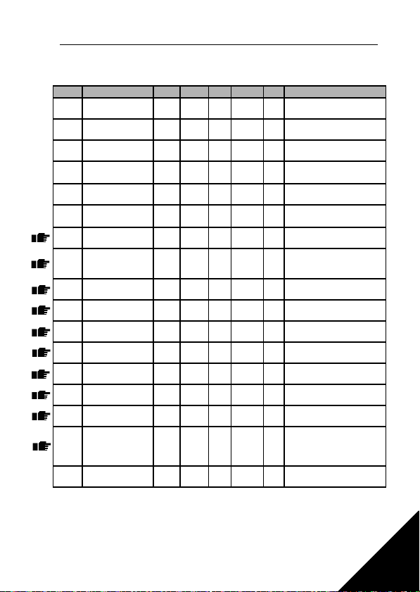
8.2 MOTOR SETTINGS (CONTROL PANEL: MENU PAR -> P1)
Code Parameter Min Max Unit Default ID Note
Motor nominal
P1.1
voltage
Motor nominal
P1.2
frequency
Motor nominal
P1.3
speed
Motor nominal
P1.4
current
P1.5
Motor cos
P1.7 Current limit
P1.8 Motor control mode 0 1 0 600
P1.9 U/f ratio selection 0 2 0 108
Field weakening
P1.10
point
Voltage at field
P1.11
weakening point
U/f curve midpoint
P1.12
frequency
U/f curve midpoint
P1.13
voltage
Output voltage at
P1.14
zero frequency
P1.15 Torque boost 0 1 0 109
Switching
P1.16
frequency
P1.17 Brake chopper 0 2 0 504
P1.18 Motor identification 0 1 0 631
180 500 V
30 320 Hz 50,00 111
300 20000 rpm 1440 112
2,0 x
0,2 x
I
I
Nunit
Nunit
0,30 1,00 0,85 120
2 x
0,2 x
I
I
Nunit
Nunit
30,00 320 Hz 50,00 602
10,00 200 % 100,00 603
0,00 P1.10 Hz 50,00 604
0,00 P1.11 % 100,00 605
0,00 40,00 % 0,00 606
1,5 16,0 kHz 6,0 601
Table 8.2: Motor settings
NOTE! These parameters are shown, when P13.1 = 0.
230
400
I
A
Nunit
1,5 x
A
I
Nunit
Check rating plate on the
110
motor
Check rating plate on the
motor
Default applies for a 4-pole
motor.
Check rating plate on the
113
motor
Check rating plate on the
motor
107
0 = Frequency control
1 = Speed control
0 = Linear
1 = Squared
2 = Programmable
% of Nominal voltage of the
motor
% of Nominal voltage of the
motor
% of Nominal voltage of the
motor
0 = Not used
1 = Used
0 = Disabled
1 = Used in Run state
2 = Used in Run and
Stop state
1 = Identification without
run after start command
8
Page 39
38 Par ameters Honeywell
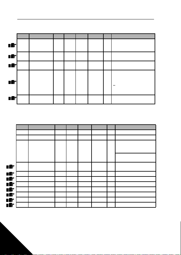
8.3 START/STOP SETUP (CONTROL PANEL: MENU PAR -> P2)
Code Parameter Min Max Unit Default ID Note
P2.1 Control place 1 3 1 125
P2.2 Start function 0 1 0 505
P2.3 Stop function 0 1 0 506
P2.4 Start/Stop logic 0 3 0 300
P2.5 Local/remote 0 1 211
Table 8.3: Start/stop setup
8.4 FREQUENCY REFERENCES (CONTROL PANEL: MENU PAR -> P3)
Code Parameter Min Max Unit Default ID Note
P3.1 Min frequency 0,00 P3.2 Hz 0,00 101
P3.2 Max frequency P3.1 320 Hz 50,00 102
P3.3 I/O reference 0 4 3 117
If P3.3 = 0, Pre-
P3.4
set speed 0
P3.5 Preset speed 1 0,00 P3.2 Hz 10,00 105 Activated by digital inputs
P3.6 Preset speed 2 0,00 P3.2 Hz 15,00 106 Activated by digital inputs
P3.7 Preset speed 3 0,00 P3.2 Hz 20,00 126 Activated by digital inputs
P3.8 Preset speed 4 0,00 P3.2 Hz 25,00 127 Activated by digital inputs
P3.9 Preset speed 5 0,00 P3.2 Hz 30,00 128 Activated by digital inputs
P3.10 Preset speed 6 0,00 P3.2 Hz 40,00 129 Activated by digital inputs
P3.11 Preset speed 7 0,00 P3.2 Hz 50,00 130 Activated by digital inputs
0,00 P3.2 Hz 5,00 124 Activated by digital inputs
Table 8.4: Frequency references
NOTE! These parameters are shown, when P13.1 = 0.
1 = I/O terminal
2 = Keypad
3 = Fieldbus
0 = Ramp
1 = Flying start
0 = Coasting
1 = Ramp
DI1 DI2
0 Start Fwd Start reverse
1 Start Reverse
2
Start Pulse Stop Pulse
3 Start Fwd Start Rv
REAF REAF
0 = Remote
1 = Keypad
0 = Preset Speeds (0-7)
1 = Keypad Reference
2 = Fieldbus Reference
3 = AI1
4 = AI2
8
Page 40
Honeywell Parameters 39
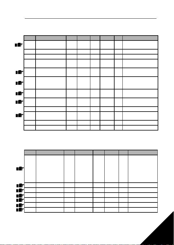
8.5 RAMPS AND BRAKES SETUP (CONTROL PANEL: MENU PAR -> P4)
Code Parameter Min Max Unit Default ID Note
P4.1 Ramp shape 0,0 10,0 s 0,0 500
P4.2 Acceleration time 0,1 3000 s 1,0 103
P4.3 Deceleration time 0,1 3000 s 1,0 104
DC braking
P4.4
current
DC braking time at
P4.5
start
Frequency to start
P4.6
DC braking during
ramp stop
DC braking time at
P4.7
stop
P4.8 Flux brake 0 3 520
P4.9 Flux braking current 0 7,4 A 519
P4.10 Ramp shape 2 0,0 10,0 s 0,0 501
P4.11 Acceleration time 2 0,1 3000 s 1,0 502
P4.12 Deceleration time 2 0,1 3000 s 1,0 503
Unit
Unit
dep.
A Varies 507
dep.
0,00 600.00 s 0 516
0,10 10,00 Hz 1,50 515
0,00 600.00 s 0 508
Table 8.5: Motor control parameters
8.6 DIGITAL INPUTS (CONTROL PANEL: MENU PAR -> P5)
Code Parameter Min Max Unit Default ID Note
P5.1 Start signal 1 0 6 1 403
P5.2 Start signal 2 0 6 2 404 As parameter 5.1
P5.3 Reverse 0 6 0 412 As parameter 5.1
P5.4 Ext. fault Close 0 6 0 405 As parameter 5.1
P5.5 Ext. fault Open 0 6 0 406 As parameter 5.1
P5.6 Fault reset 0 6 5 414 As parameter 5.1
P5.7 Run enable 0 6 0 407 As parameter 5.1
Table 8.6: Digital inputs
0 = Linear
>0 = S-curve ramp time
0 = DC brake is off at
start
0 = DC brake is off at
stop
0 = Off 2 = Chopper
1 = On 3 = Full mode
0 = Linear
>0 = S-curve ramp time
0 = Not used
1 = DI1
2 = DI2
3 = DI3
4 = DI4
5 = DI5
6 = DI6
8
Page 41
40 Par ameters Honeywell
Code Parameter Min Max Unit Default ID Note
P5.8 Preset speed B0 0 6 3 419 As parameter 5.1
P5.9 Preset speed B1 0 6 4 420 As parameter 5.1
P5.10 Preset speed B2 0 6 0 421 As parameter 5.1
P5.11 Disable PI 0 6 6 1020 As parameter 5.1
P5.12 Force to I/O 0
P5.13 Ramp time select 0 6 0 408 As parameter 5.1
Table 8.6: Digital inputs
8.7 ANALOGUE INPUTS (CONTROL PANEL: MENU PAR -> P6)
Code Parameter Min Max Unit Default ID Note
P6.1 AI1 Signal range 0 3 0 379
P6.2 AI1 filter time 0,0 10,0 s 0,1 378 0 = no filtering
P6.3 AI1 Custom min -100,0 100,0 % 0,0 380 0,0 = no min scaling
P6.4 AI1 Custom max -100,0 100,0 % 100,0 381 100,0 = no max scaling
P6.5 AI2 signal range 2 3 3 390
P6.6 AI2 filter time 0,0 10,0 s 0,1 389 0 = no filtering
P6.7 AI2 Custom min -100,0 100,0 % 0,0 391 0,0 = no min scaling
P6.8 AI2 Custom max -100,0 100,0 % 100,0 392 100,0 = no max scaling
Table 8.7: Analoque inputs
1
6 (RS485)
0 409 As parameter 5.1
0 = Voltage 0…10 V
1 = Voltage 2…10 V
2 = Current 0…20 mA
3 = Current 4…20 mA
8
Page 42
Honeywell Parameters 41
8.8 DIGITAL AND ANALOGUE OUTPUTS (CONTROL PANEL: MENU PAR -> P7)
Code Parameter Min Max Unit Default ID Selections
Relay output 1
P7.1
content
Relay output 2
P7.2
content
Digital output 1
P7.3
content
Analogue output
P7.4
function
Analogue output
P7.5
minimum
P7.6 Relay 2 invert 0 1 0 489 1 = Relay 2 inverted
0 11 2 313
0 8 3 314 As parameter 7.1
0 8 1 312 As parameter 7.1
0 4 1 307
0 1 1 310
Table 8.8: Digital and analogue outputs
0 = Not used
1 = Ready
2 = Run
3 = Fault
4 = Fault Inverted
5 = Warning
6 = Reversed
7 = At Speed
8 = Motor Regulator Active
9 = FBControlWord.B13
10 = FBControlWord.B14
11 = FBControlWord.B15
0 = Not in use
1 = Output freq. (0-f
2 = Output current (0-I
3 = Torque (0-Nominal
torque)
4 = PI controller output
0 = 0 mA
1 = 4 mA
max
)
nMotor
)
8
Page 43
42 Par ameters Honeywell
8.9 PROTECTIONS (CONTROL PANEL: MENU PAR -> P9)
Code Parameter Min Max Unit Default ID Note
Response to 4mA
P9.1
reference fault
Response to under
P9.2
voltage fault
P9.3 Earth fault protection 0 2 2 703
P9.4 Stall protection 0 2 1 709
P9.5 Underload protection 0 2 0 713
P9.6 Reserved
Thermal protection of
P9.7
the motor
Motor ambient
P9.8
temperature
Motor cooling factor
P9.9
at zero speed
Motor thermal time
P9.10
constant
Motor Phase
P9.11
Supervision
Table 8.9: Protections
NOTE! These parameters are shown, when P13.1 = 0.
8.10 AUTORESTART PARAMETERS (CONTROL PANEL: MENU PAR -> P10)
Code Parameter Min Max Unit Default ID Note
P10.1 Wait time 0,10 10,00 s 0,50 717
P10.2 Trial time 0,00 60,00 s 30,00 718
P10.3 Start function 0 2 0 719
Automatic
P10.4
restart
Table 8.10: Autorestart parameters
NOTE! These parameters are shown, when P13.1 = 0.
0 2 1 700
0 2 2 727
0 2 2 704
-20 100 C 40 705
0,0 150,0 % 40,0 706
1 200 min 45 707
0 2 unit 2 702
0 1 0 731
0 = No response
1 = Warning
2 = Fault, stop acc. to
P2.3
0 = No response
1 = Warning
2 = Fault, stop mode after
fault according to P2.3
Delay before automatic restart
after a fault has disappeared
Defines the time before the
inverter tries to automatically
restart the motor after the fault
has disappeared
0 = Ramp
1 = Flying start
2 = According to P4.2
0 = Disabled
1 = Enabled
8
Page 44
Honeywell Parameters 43
8.11 PI CONTROL PARAMETERS (CONTROL PANEL: MENU PAR -> P12)
Code Parameter Min Max Unit Default ID Note
P12.1 PI activation 0 2 0 163
P12.2 PI controller gain 0,0 1000 % 100,0 118
PI controller
P12.3
I-time
Keypad PI
P12.4
reference
P12.5 Setpoint source 0 3 0 332
P12.6 Feedback source 0 2 2 334
Feedback
P12.7
minimum
Feedback
P12.8
maximum
Error value
P12.9
inversion
0,00 320,0 s 10,00 119
0,0 100,0 % 0,0 167
0,0 100,0 % 0,0 336 0 = No minimum scaling
0,0 100,0 % 100,0 337
0 1 0 340
Table 8.11: PI control parameters
NOTE! These parameters are shown, when P13.1 = 0.
0 = Not used
1 = PI for motor control
2 = PI for external use
0 = Keypad PI reference,
P12.4
1 = Fieldbus
2 = AI1
3 = AI2
0 = Fieldbus
1 = AI1
2 = AI2
100,0 = No maximum
scaling
0 = No inversion (Feedback<Setpoint->Increase
PI Output)
1 = Inverted
(Feedback<Setpoint>Decrease PI Output)
8
Page 45
44 Par ameters Honeywell
8.12 EASY USAGE MENU (CONTROL PANEL: MENU PAR -> P0)
Code Parameter Min Max Unit Default ID Note
Parameter
P13.1
conceal
P13.2 Drive setup 0 3 0 540
01 1 115
Table 8.12: Easy usage menu parameters
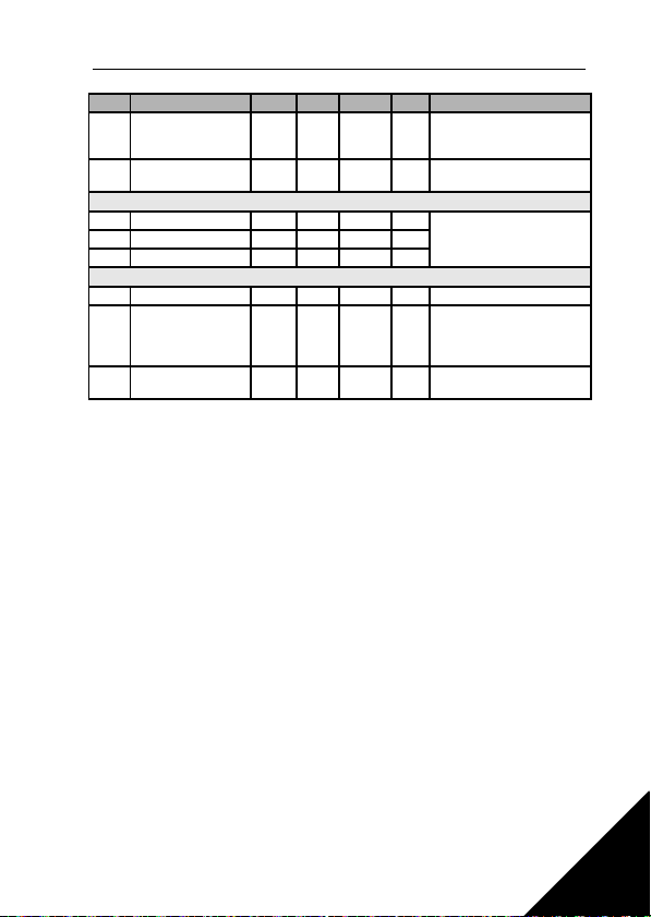
8.13 SYSTEM PARAMETERS
Code Parameter Min Max Default ID Note
Software information (MENU PAR -> S1)
S1.1 System SW 2314
S1.2 System SW version 835
S1.3 Power SW ID 2315
S1.4 Power SW version 834
S1.5 Application SW ID 837
Application SW
S1.6
revision
S1.7 System load 839
RS485 information (MENU PAR -> S2)
Communication
S2.1
status
S2.2 Fieldbus protocol 0 1 0 809 0 = FB disabled 1 = Modbus
S2.3 Slave address 1 255 1 810
S2.4 Baud rate 0 5 5 811
S2.5 Number of stop bits 0 1 1 812 0 = 1, 1 = 2
S2.6 Parity type 0 0 0 813 0 = None (locked)
Table 8.13: System parameters
0 = All parameters visible
1 = Only quick setup parameter
group visible
0 = Basic
1 = Pump drive
2 = Fan drive
3 = Conveyor drive (HP)
NOTE! Visible only duriing
Startup wizard
838
Format: xx.yyy
xx = 0 - 64 (Number of error
808
messages)
yyy = 0 - 999 (Number of
correct messages)
0 = 300, 1 = 600,
2 = 1200, 3 = 2400,
4 = 4800, 5 = 9600,
8
Page 46
Honeywell Parameters 45
Code Parameter Min Max Default ID Note
Communication time-
S2.7
out
Reset communica-
S2.8
tion status
0 255 0 814
0 = Not used,
1 = 1 second,
2 = 2 seconds, etc.
815 1 = Resets par. S2.1
Total counters (MENU PAR -> S3)
S3.1 MWh counter 827
S3.2 Power on days 828
S3.3 Power on hours 829
User settings (MENU PAR -> S4)
S4.1 Display contrast 0 15 7 830 Adjusts the display contrast
S4.2 Default page 0 20 0 2318
Restore factory
S4.3
defaults
0 1 0 831
Defines which monitoring
page (1.1. - 1.20) is shown
after startup.
0 = Not used
1 = Restores factory defaults
for all parameters
Table 8.13: System parameters
NOTE! These parameters are shown, when P13.1 = 0.
8
Page 47

9
46 Parameter Descriptions Honeywell
9. PARAMETER DESCRIPTIONS
On the next pages you can find the descriptions of certain parameters. The descriptions have been arranged according to parameter group and number.
9.1 MOTOR SETTINGS (CONTROL PANEL: MENU PAR -> P1)
1.8 MOTOR CONTROL MODE
With this parameter the user can select the motor control mode. The selections are:
0 = Frequency control:
The I/O terminal, keypad and fieldbus references are frequency references and the inverter controls the output frequency (output frequency
resolution = 0.01 Hz)
1 = Speed control:
The I/O terminal, keypad and fieldbus references are speed references
and the inverter controls the motor speed.
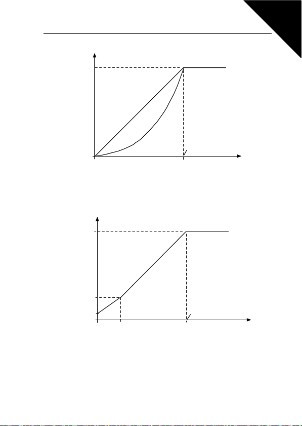
1.9 U/F RATIO SELECTION
There are three selections for this parameter:
0 = Linear:
The voltage of the motor changes linearly with the frequency in the
constant flux area from 0 Hz to the field weakening point where the
nominal voltage is supplied to the motor. Linear U/f ratio should be
used in constant torque applications. See Figure 9.1.
This default setting should be used if there is no special need for another setting.
1 = Squared:
The voltage of the motor changes following a squared curve form with
the frequency in the area from 0 Hz to the field weakening point where
the nominal voltage is also supplied to the motor. The motor runs under magnetised below the field weakening point and produces less
torque, power losses and electromechaniqal noise. Squared U/f ratio
can be used in applications where torque demand of the load is proportional to the square of the speed, e.g in centrifugal fans and pumps
Page 48
Un
par.1.11
U[V]
f[Hz ]
par.1.10
par. 1.14
Default: Nominal
voltage of the motor
Linear
Squared
F iel d we ake ni ng
point
Default: Nominal
frequency of the
motor
Un
Par 1. 11
Par. 1.10
U[V ]
f[Hz]
Par. 1.13
(Def. 50%)
Par. 1.14
(Def. 0.0%)
Defa ult: Nom ina l
voltage of the motor
Field weakening
point
Default: Nominal
frequency of the
motor
Par. 1.12
(Def. 10%)
Honeywell Parameter Descriptions 47
Figure 9.1: Linear and squared change of motor voltage
2 = Programmable U/f curve:
The U/f curve can be programmed with three different points. Programmable U/f curve can be used if the other settings do not satisfy the
needs of the application.
Figure 9.2: Programmable U/f curve
1.10 FIELD WEAKENING POINT
The field weakening point is the output frequency at which the output voltage
reaches the value set with par. 1.11.
9
Page 49

9
48 Parameter Descriptions Honeywell
1.11 VOLTAGE AT FIELD WEAKENING POINT
Above the frequency at the field weakening point, the output voltage remains
at the value set with this parameter. Below the frequency at the field weakening point, the output voltage depends on the setting of the U/f curve parameters. See parameters 1.9 - 1.14 and Figures 9.1 and 9.2.
When the parameters 1.1 and 1.2 (nominal voltage and nominal frequency of
the motor) are set, the parameters 1.10 and 1.11 are automatically given the
corresponding values. If you need different values for the field weakening point
and the voltage, change these parameters after setting the parameters 1.1
and 1.2.
1.12 U/F CURVE, MIDDLE POINT FREQUENCY
If the programmable U/f curve has been selected with the parameter 1.9, this
parameter defines the middle point frequency of the curve. See Figure 9.2.
1.13 U/F CURVE, MIDDLE POINT VOLTAGE
If the programmable U/f curve has been selected with the parameter 1.9, this
parameter defines the middle point voltage of the curve. See Figure 9.2.
1.14 OUTPUT VOLTAGE AT ZERO FREQUENCY
This parameter defines the zero frequency voltage of the curve. See Figures
9.1 and 9.2.
1.15 TORQUE BOOST
The voltage to the motor changes automatically with high load torque which
makes the motor produce sufficient torque to start and run at low frequencies.
The voltage increase depends on the motor type and power. Automatic torque
boost can be used in applications with high load torque, e.g. in conveyors.
0 = Disabled
1 = Enabled
Note: In high torque - low speed applications - it is likely that the motor will
overheat. If the motor has to run a prolonged time under these conditions, special attention must be paid to cooling the motor. Use external cooling for the
motor if the temperature tends to rise too high.
1.16 SWITCHING FREQUENCY
Motor noise can be minimised using a high switching frequency. Increasing
the switching frequency reduces the capacity of the inverter unit.
Switching frequency for SmartDrive Compact: 1.5…16 kHz.
Page 50

Honeywell Parameter Descriptions 49
1.17 BRAKE CHOPPER
Note: An internal brake chopper is installed in three phase supply MI2 and MI3
size drives
0 = No brake chopper used
1 = Brake chopper used in Run state
2 = Used in Run and Stop state
When the inverter is decelerating the motor, the energy stored to the inertia of
the motor and the load are fed into an external brake resistor, if the brake
chopper has been activated. This enables the inverter to decelerate the load
with a torque equal to that of acceleration (provided that the correct brake resistor has been selected). See separate Brake resistor installation manual.
9
Page 51

9
50 Parameter Descriptions Honeywell
9.2 START/STOP SETUP (CONTROL PANEL: MENU PAR -> P2)
2.1 CONTROL PLACE
With this parameter, the user can select the active control place. The selections are:
1 = I/O terminal
2 = Keypad
3 = Fieldbus
Note: Local/Remote control mode can be toggled by pressing the navigation
wheel for 5 seconds. P2.1 will have no effect in local mode.
Local = Keypad is the control place
Remote = P2.1 defines the control place
2.2 START FUNCTION
The user can select two start functions for SmartDrive Compact with this parameter:
0 = Ramp start
The inverter starts from 0 Hz and accelerates to the set frequency reference within the set acceleration time (P4.2). (Load inertia or starting
friction may cause prolonged acceleration times).
1 = Flying start
The inverter is able to start also a running motor by applying a small
torque to motor and searching for the frequency corresponding to the
speed the motor is running at. The searching starts from the maximum
frequency towards the actual frequency until the correct value is detected. Thereafter, the output frequency will be increased/decreased
to the set reference value according to the set acceleration/deceleration parameters.
Use this mode if the motor is rotating when the start command is given.
With the flying start, it is possible to ride through short mains voltage
interruptions.
2.3 STOP FUNCTION
Two stop functions can be selected in this application:
0 = Coasting
The motor coasts to a halt without control from the inverter after the
Stop command.
Page 52
Honeywell Parameter Descriptions 51
1 = Ramp stop
After the Stop command, the speed of the motor is decelerated according to the set deceleration parameters.
If the regenerated energy is high it may be necessary to use an external braking resistor for to be able to decelerate the motor in acceptable
time.
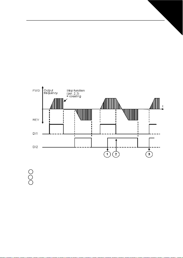
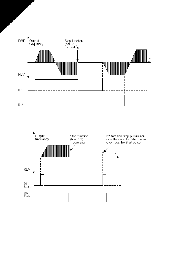
2.4 START/STOP LOGI C
With this parameter the user can select the start/stop logic.
0 = DI1 = Start forward
DI2 = Start reverse
Figure 9.3: Start/Stop logic, selection 0
1 The first selected direction has the highest priority.
2 When the DIN1 contact opens the direction of rotation starts the change.
3 If Start forward (DI1) and Start reverse (DI2) signals are active simultaneously the
Start forward signal (DI1) has priority.
9
Page 53
9
52 Parameter Descriptions Honeywell
1 = DI1 = Start
DI2 = Reverse
Figure 9.4: Start/Stop logic, selection 1
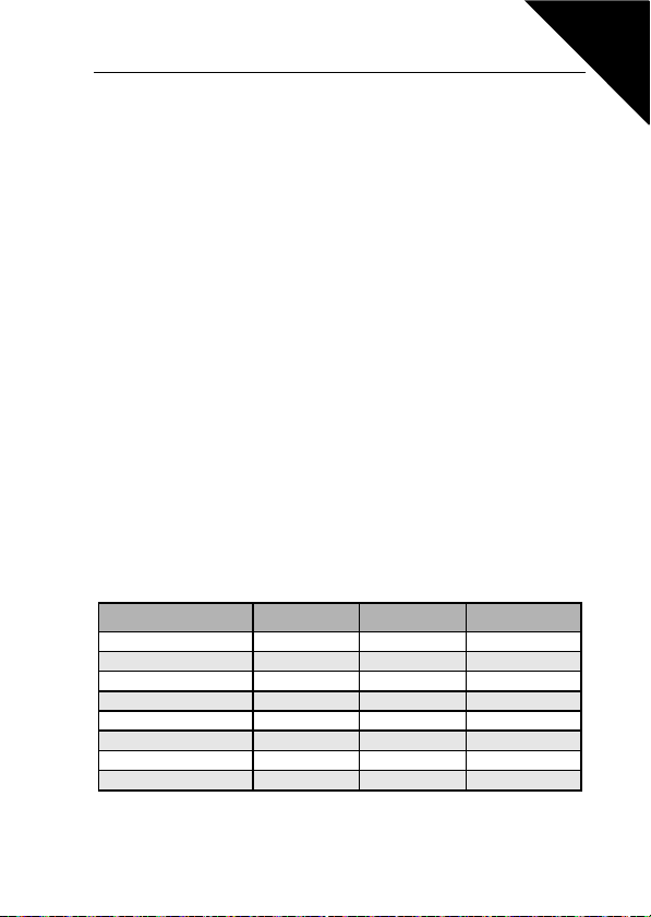
2 = DI1 = Start pulse
DI2 = Stop pulse
Figure 9.5: Start/Stop logic, selection 2
3 = DI1 = Start forward, rising edge after fault
DI2 = Start reverse, rising edge after fault
Page 54
Honeywell Parameter Descriptions 53
2.5 LOCAL/REMOTE
This parameter defines whether the control place of the drive is remote (I/O or
FieldBus) or Keypad. Keypad can also be selected as control place by pressing the navigation wheel for 5 seconds.
The priority order of selecting control place is
1. Navigation wheel
2. Forced from I/O
3. Parameter 2.1
9.3 FREQUENCY REFERENCES (CONTROL PANEL: MENU PAR -> P3)
3.3 I/O REFERENCE
Defines the selected frequency reference source when the drive is controlled
from the I/O terminal.
0 = Preset speed 0 - 7
1 = Keypad reference
2 = Reference from Fieldbus (FBSpeedReference)
3 = AI1 reference (terminals 2 and 3, e.g. potentiometer)
4 = AI2 reference (terminal 4 and 5, e.g. transducer)
3.4 - 3.11 PRESET SPEEDS 0 - 7
These parameters can be used to determine frequency references that are applied when appropriate combinations of digital inputs are activated. Preset
speeds can be activated from digital inputs despite of the active control place.
Parameter values are automatically limited between the minimum and maximum frequencies. (par. 3.1, 3.2).
Speed Preset speed B2 Preset speed B1 Preset speed B0
If P3.3 = 0, Preset speed 0
Preset speed 1 x
Preset speed 2 x
Preset speed 3 x x
Preset speed 4 x
Preset speed 5 x x
Preset speed 6 x x
Preset speed 7 x x x
Table 9.1: Preset speeds 1 - 7
9
Page 55
9
P4.2, 4.3
[Hz]
[t]
P4.1
P4.1
54 Parameter Descriptions Honeywell
9.4 RAMPS & BRAKES SETUP (CONTROL PANEL: MENU PAR -> P4)
4.1 RAMP SHAPE
4.10 RAMP SHAPE 2
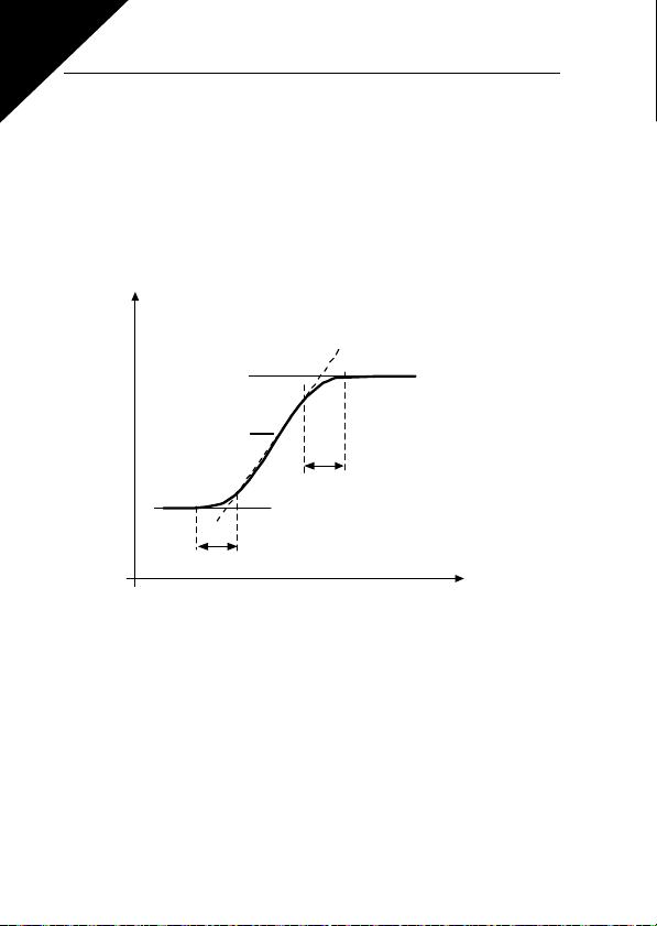
The start and end of the acceleration and deceleration ramp can be smoothed
with this parameter. Setting value 0 gives a linear ramp shape which causes
acceleration and deceleration to act immediately to the changes in the reference signal.
Setting value 0.1…10 seconds for this parameter produces an S-shaped acceleration/deceleration. The acceleration and deceleration times are determined with parameters 4.2 and 4.3.
Figure 9.6: S-shaped acceleration/deceleration
4.2 ACCELERATION TIME
4.3 DECELERATION TIME
4.11 ACCELERATION TIME 2
4.12 DECELERATION TIME 2
These limits correspond to the time required for the output frequency to accelerate from the zero frequency to the set maximum frequency, or to deceleratefrom the set maximum frequency to zero frequency.
The user can set two different acceleration/deceleration time sets for one application.
The active set can be selected with the selected digital input (par. 5.13)
Page 56
t
Par 4.5
RUN
STO P
Output
frequency
Honeywell Parameter Descriptions 55
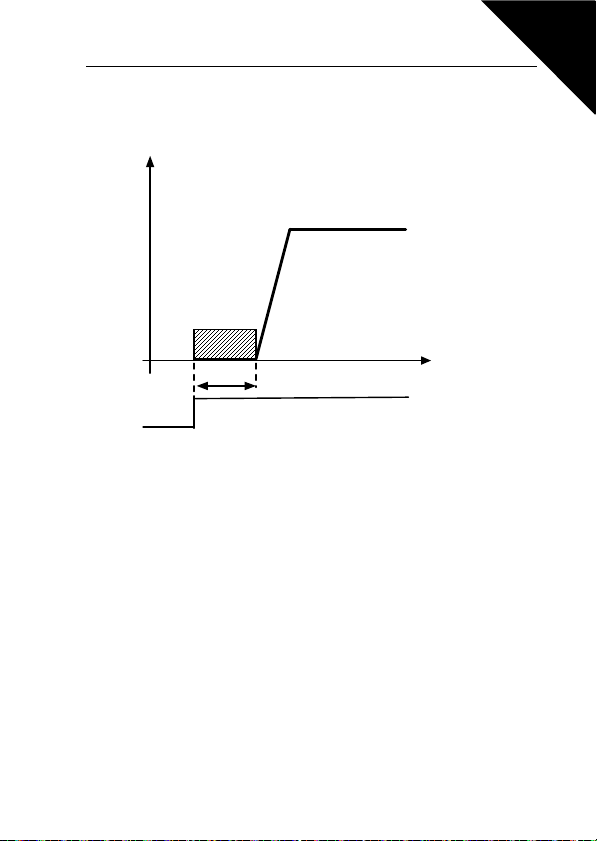
4.5 DC BRAKING TIME AT START
DC-brake is activated when the start command is given. This parameter defines the time before the brake is released. After the brake is released, the output frequency increases according to the set start function by par. 2.2.
Figure 9.7: DC braking time at start
4.6 FREQUENCY TO START DC BRAKING DURING RAMP STOP
The output frequency at which the DC-braking is applied. See Figure 9.9.
9
Page 57
9
f
n
f
n
t
t
t = 1 x p ar. 4.7
t = 0,1 x par. 4.7
0,1 x f
n
RUN
STOP
RUN
STOP
Output frequency
Motor speed
Output frequency
Motor speed
DC-braking O N
DC-braking ON
f
out
f
out
56 Parameter Descriptions Honeywell
4.7 DC BRAKING TIME AT STOP
Determines if braking is ON or OFF and the braking time of the DC-brake
when the motor is stopping. The function of the DC-brake depends on the stop
function, par. 2.3.
0 = DC brake is not in use
>0 = DC brake is in use and its function depends on the Stop function,
(par. 2.3). The DC braking time is determined with this parameter.
Par. 2.3 = 0 (Stop function = Coasting):
After the stop command, the motor coasts to a stop without control from the
inverter.
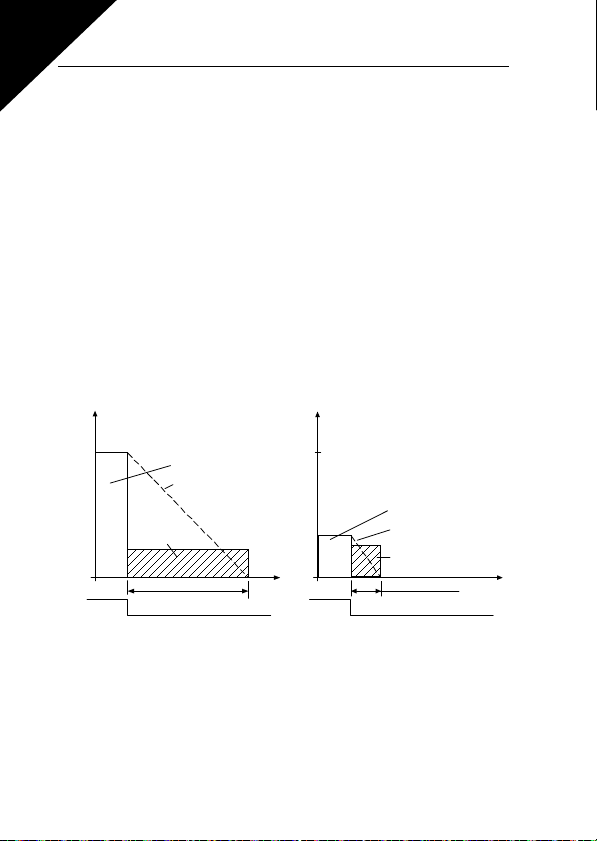
With the DC injection, the motor can be electrically stopped in the shortest
possible time, without using an optional external braking resistor.
The braking time is scaled by the frequency when the DC-braking starts. If the
frequency is greater than the nominal frequency of the motor, the set value of
parameter 4.7 determines the braking time. When the frequency is 10% of the
nominal, the braking time is 10% of the set value of parameter 4.7.
Figure 9.8: DC-braking time when Stop mode = Coasting
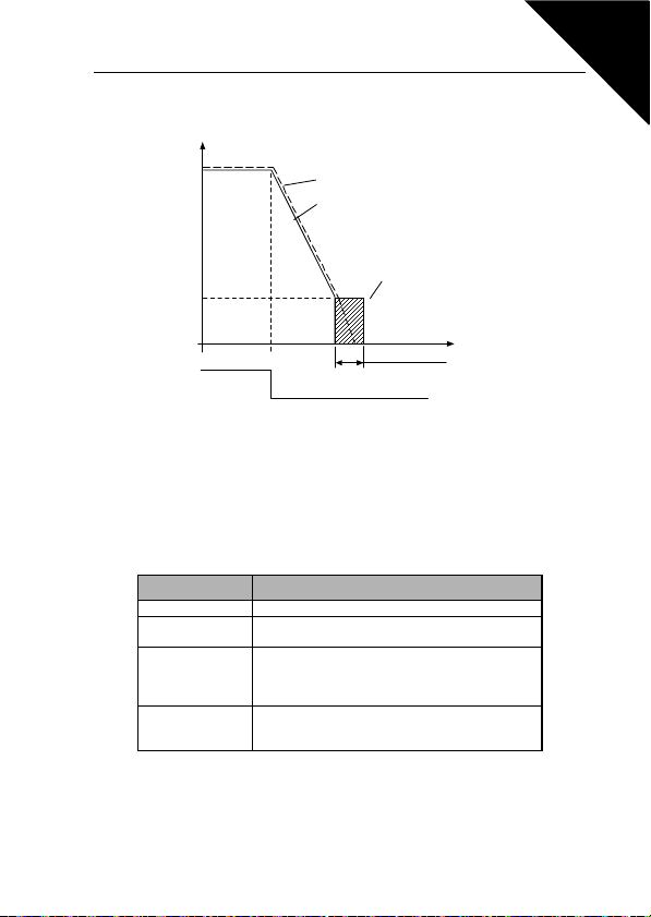
Par. 2.3 = 1 (Stop function = Ramp):
After the Stop command, the speed of the motor is reduced according to the
set deceleration parameters, if the inertia of of the motor and load allows that,
to the speed defined with parameter 4.6, where the DC-braking starts.
Page 58
t = par. 4.7
t
Par. 4.6
Motor speed
Output frequency
DC-braking
RUN
STOP
f
out
Honeywell Parameter Descriptions 57
The braking time is defined with parameter 4.7. If high inertia exists, it is recommended to use an external braking resistor for faster deceleration. See Figure 9.9.
Figure 9.9: DC-braking time when Stop mode = Ramp
4.8 FLUX BRAKE
Instead of DC braking, flux braking is a useful form of braking with motors of
max. 15kW.
When braking is needed, the frequency is reduced and the flux in the motor is
increased, which in turn increases the motor's capability to brake. Unlike DC
braking, the motor speed remains controlled during braking.
Activation mode Description
0 = Off Not used
1 = On
2 = Chopper
3 = Full mode
Note! Flux braking converts the energy into heat at the motor, and should be
used intermittently to avoid motor damage.
Normal mode. Activates flux bracking during
deceleration regardless of load.
Emulates the behavior of a braking chopper by
activating flux bracking based on DC-link voltage.
Minimizes the heating up of the motor in applications
with frequent speed changes.
Activates flux bracking both during deceleration and
on generative shock loads at constant speed. Offers
the highest performance in demanding applications.
9
Page 59

9
58 Parameter Descriptions Honeywell
9.5 DIGITAL INPUTS (CONTROL PANEL: MENU PAR -> P5)
The selections for these parameters are:
0 = Not used
1 = DI1
2 = DI2
3 = DI3
4 = DI4
5 = DI5
6 = DI6
5.1 START SIGNAL 1
5.2 START SIGNAL 2
5.3 REVERSE
5.4 EXTERNAL FAULT (CLOSE)
5.5 EXTERNAL FAULT (OPEN)
5.6 FAULT RESET
5.7 RUN ENABLE
5.8 PRESET SPEED B0
5.9 PRESET SPEED B1
5.10 PRESET SPEED B2
5.11 DISABLE PI
5.12 FORCE TO I/O
The control place is forced to I/O by activating the digital input that this function
is programmed to.
The priority order of selecting control place is
1. Navigation wheel
2. Forced from I/O
3. Parameter 2.1
5.13 RAMP TIME SELECTION
Contact open: Acceleration/Deceleration time 1 selected
Contact closed: Acceleration/Deceleration time 2 selected
Set Acceleration/Deceleration times with parameters 4.2 and 4.3 and the alternative ramp times with 4.11 and 4.12.
Page 60
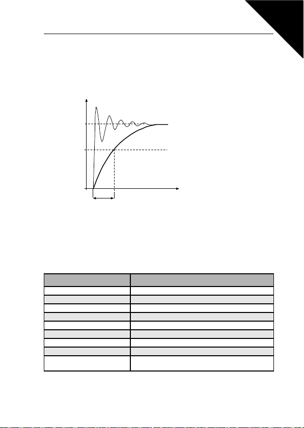
%
100%
63%
Par. 6.2
Par. 6.6
t [s]
Filtered signal
Unfiltered signal
Honeywell Parameter Descriptions 59
9
9.6 ANALOQUE INPUTS (CONTROL PANEL: MENU PAR -> P6)
6.2 AI1 SIGNAL FILTER TIME
6.6 AI2 SIGNAL FILTER TIME
This parameter, given a value greater than 0, activates the function that filters
out disturbances from the incoming analogue signal. Long filtering time makes
the regulation response slower. See Figure 9.10.
Figure 9.10: AI1 and AI2 signal filtering
9.7 DIGITAL AND ANALOQUE OUTPUTS (CONTROL PANEL: MENU PAR -> P7)
7.1 RELA Y OUTPUT 1 FUNCTION
7.2 RELA Y OUTPUT 2 FUNCTION
7.3 DIG ITAL OUTPUT 1 FUNCTION
Setting Signal content
0 = Not used Not in operation
1 = Ready The inverter is ready to operate
2 = Run The inverter operates (motor is running)
3 = Fault A fault trip has occurred
4 = Fault inverted A fault trip has not occurred
5 = Alarm An alarm has occurred
6 = Reversed The reverse command has been selected
7 = At speed The output frequency has reached the set reference
8 = Motor regulator activated
One of the limit regulators (e.g. current limit, voltage
limit) is activated
Table 9.2: Output signals via RO1, RO2 and DO1
Page 61

9
60 Parameter Descriptions Honeywell
9.8 MOTOR THERMAL PROTECTION (PARAMETERS 9.7 - 9.10)
The motor thermal protection is to protect the motor from overheating. The Honeywell drive is capable of supplying higher than nominal current to the motor. If the load
requires this high current there is a risk that the motor will be thermally overloaded.
This is the case especially at low frequencies. At low frequencies the cooling effect
of the motor is reduced as well as its capacity. If the motor is equipped with an external fan the load reduction at low speeds is small.
The motor thermal protection is based on a calculated model and it uses the output
current of the drive to determine the load on the motor.
The motor thermal protection can be adjusted with parameters. The thermal current
IT specifies the load current above which the motor is overloaded. This current limit
is a function of the output frequency.
CAUTION! The calculated model does not protect
the motor if the airflow to the
motor is reduced by blocked air intake grill
9.7 THERMAL PROTECTION OF THE MOTOR
9.8 MOTOR AMBIENT TEMPERATURE
0 = No response
1 = Warning
2 = Fault, stop mode after fault according to parameter 2.3
If tripping is selected the drive will stop and activate the fault stage. Deactivating the protection, i.e. setting parameter to 0, will reset the thermal model of
the motor to 0%.
When the motor ambient temperature must be taken into consideration, it is
recommended to set a value for this parameter. The value can be set between
-20 and 100 degrees Celsius.
Page 62
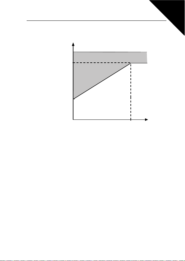
Honeywell Parameter Descriptions 61
f
f
n
par.9.9=40%
0
I
T
100%
Overlo ad area
P
cooling
9.9 MOTOR COOLING FACTOR AT ZERO SPEED
The cooling power can be set between 0-150.0% x cooling power at nominal
frequency. See Figure 9.11.
Figure 9.11: Motor cooling power
9.10 MOTOR THERMAL TIME CONSTANT
This time can be set between 1 and 200 minutes.
This is the thermal time constant of the motor. The bigger the motor, the bigger
the time constant. The time constant is the time within which the calculated
thermal model has reached 63% of its final value.
The motor thermal time is specific to the motor design and it varies between
different motor manufacturers.
9
Page 63
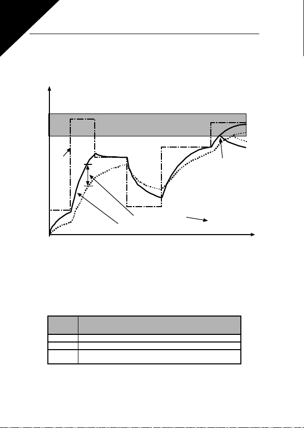
9
105%
par. 9.7
Q = (I/IT)2 x (1-e
-t/T
)
I/I
T
Trip area
Motor tempera ture
Time
Motor temperature
Time constant T
*)
*)
Changes by motor size and
adj ust ed wi th pa rameter 9 .1 0
Fault/warning
Motor
current
62 Parameter Descriptions Honeywell
If the motor's t6-time (t6 is the time in seconds the motor can safely operate at
six times the rated current) is known (given by the motor manufacturer) the
time constant parameter can be set basing on it. As a rule of thumb, the motor
thermal time constant in minutes equals to 2xt6. If the drive is in stop state the
time constant is internally increased to three times the set parameter value.
See also Figure 9.12.
Figure 9.12: Motor temperature calculation
9.11 MOTOR PHASE SUPERVISION
Motor phase supervision of the motor ensures that the motor phases have an
approximately equal current.
Settings for P9.11, range 0-2:
Activation
Mode
0 No response
1 Warning
2 Fault, stop mode after fault according to ID506 (P2.3 stop func-
tion)
Description
Page 64
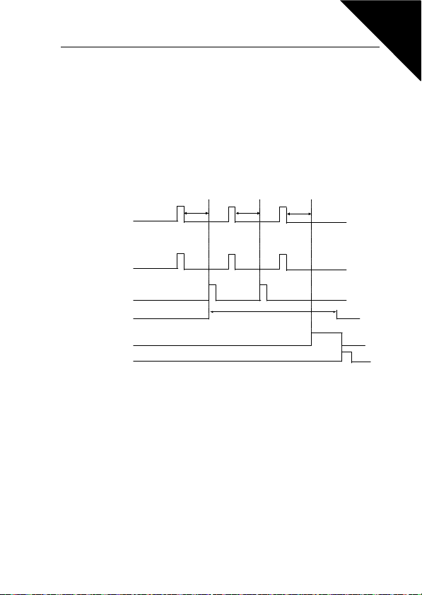
Fault trigger
Motor stop si gnal
Motor start signal
Sup ervision
Wait time
par.1 0.1
Restart 1 Restart 2
Trial time
par.10.2
Fault active
RE SET /
Fault reset
Autoreset function: (Trials = 2)
Wait time
par.1 0.1
Wait ti me
par.1 0.1
Honeywell Parameter Descriptions 63
9.9 AUTORESTART PARAMETERS (CONTROL PANEL: MENU PAR -> P10)
10.2 AUTOMATIC RESTART, TRIAL TIME
The Automatic restart function restarts the inverter when the faults have disappeared and the waiting time has elapsed.
The time count starts from the first autorestart. If the number of faults occurring
during the trial time exceeds three, the fault state becomes active. Otherwise
the fault is cleared after the trial time has elapsed and the next fault starts the
trial time count again. See Figure 9.13.
If a single fault remains during the trial time, a fault state is true.
Figure 9.13: Automatic restart
9.10 PI CONTROL PARAMETERS (CONTROL PANEL: MENU PAR -> P12)
12.2 PI CONTROLLER GAIN
12.3 PI CONTROLLER I-TIME
This parameter defines the gain of the PI controller. If the value of the parameter is set to 100% a change of 10% in the error value causes the controller
output to change by 10%.
This parameter defines the integration time of the PI controller. If this parameter is set to 1,00 second the controller output is changed by a value corresponding to the output caused from the gain every second. (Gain*Error)/s.
9
Page 65
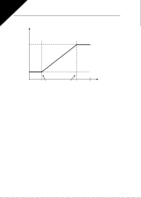
9
0V
0mA
par. 12.7
Custom min
par. 6.3/6.7
Custom max
par.6.4/6.8
par. 12.8
10V
20mA
Controller
feedback (%)
Analoque input
with cust om
min and max
scaling (%)
64 Parameter Descriptions Honeywell
12.7 FEEDBACK MINIMUM
12.8 FEEDBACK MAXIMUM
Figure 9.14: Feedback minimum and maximum
Page 66
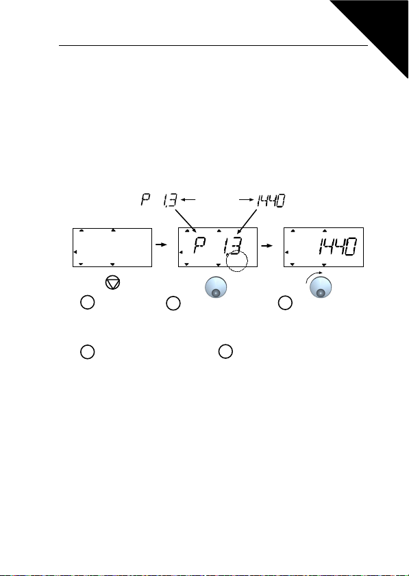
Honeywell Parameter Descriptions 65
FAULTALARMSTOPRE ADY RUN
REF
MON
PAR
FLT
FAULTALARMSTO PREADY R UN
REF
MON
PAR
FLT
FAULTALARMSTOPREADY RUN
REF
MON
PAR
FLT
rpm
Push to enter edit mode
Select motor
nominal speed
and push
to confirm.
Press STOP
for 5 secon ds
in main men u
1
4
3
PERFO RM T HE SAME
PROCEDURE FOR PAR. 1.4,
MOTOR NOM INAL CURRENT
5
PERFORM DRI VE SETUP,
PAR. 13.2, SEE NEXT PAGE
2
Alternates
in the display
9
9.11 EASY USAGE MENU (CONTROL PANEL: MENU PAR -> P9)
13.2 DRIVE SETUP
With this parameter you can easily set up your drive for four different applications.
Note! This parameter is only visible when the Startup Wizard is active. The
startup wizard will start in first power-up. It can also be started as follows. See
the figures below.
NOTE! Running the startup wizard will always return all pa-
rameter settings to their factory defaults!
Figure 9.15: Startup wizard
Page 67
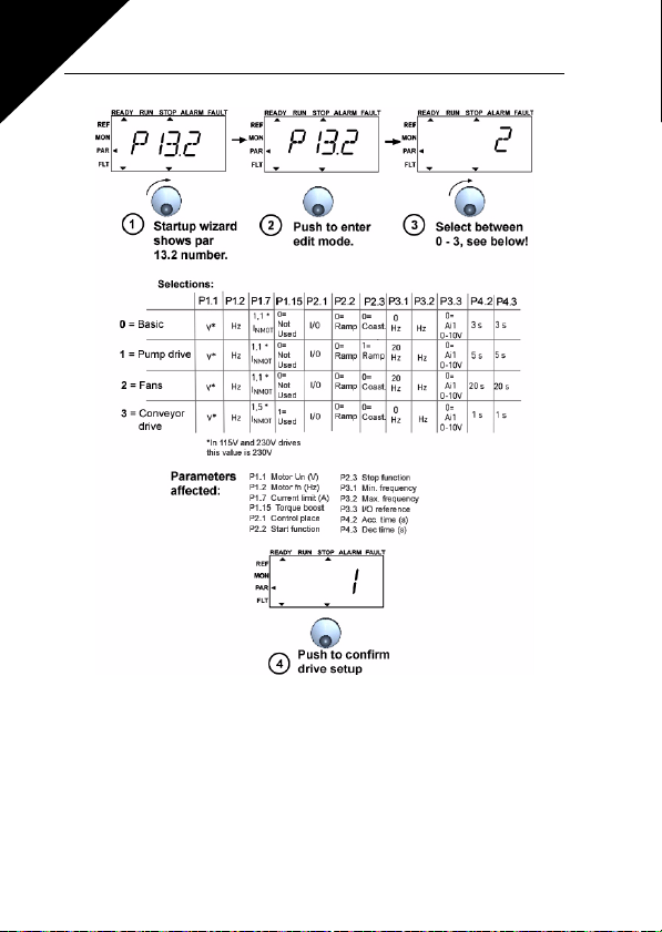
9
66 Parameter Descriptions Honeywell
Figure 9.16: Drive setup
9.12 FIELDBUS PARAMETERS (CONTROL PANEL: MENU PAR -> S2)
The built-in Modbus connection of SmartDrive Compact supports the following function codes:
- 03 Read Holding Registers
- 04 Read Input Registers
- 06 Preset Single Registers
Page 68
Honeywell Parameter Descriptions 67
9.12.1 Modbus process data
Process data is an address area for fieldbus control. Fieldbus control is active when
the value of parameter 2.1 (Control place) is 3 (=fieldbus). The contents of the process data has been determined in the application. The following tables present the
process data contents in the GP Application.
ID Modbus register Name Scale Ty pe
2101 32101, 42101 FB Status Word - Binary coded
2102 32102, 42102 FB General Status Word - Binary coded
2103 32103, 42103 FB Actual Speed 0,01 %
2104 32104, 42104 Motor freq. 0,01 +/- Hz
2105 32105, 42105 Motor speed 1 +/- Rpm
2106 32106, 42106 Motor current 0,01 A
2107 32107, 42107 Motor torque 0,1 +/- % (of nominal)
2108 32108, 42108 Motor power 0,1 +/- % (of nominal)
2109 32109, 42109 Motor voltage 0,1 V
2110 32110, 42110 DC voltage 1 V
2111 32111, 42111 Active fault - Fault code
Table 9.3: Output process data
ID Modbus register Name Scale Typ e
2001 32001, 42001 FB Control Word - Binary coded
2002 32002, 42002 FB General Control Word - Binary coded
2003 32003, 42003 FB Speed Reference 0,01 %
2004 32004, 42004 PI Control Reference 0,01 %
2005 32005, 42005 PI Actual value 0,01 %
2006 32006, 42006 - - 2007 32007, 42007 - - 2008 32008, 42008 - - 2009 32009, 42009 - - 2010 32010, 42010 - - 2011 32011, 42011 - - -
Table 9.4: Input process data
9
Page 69
9
68 Parameter Descriptions Honeywell
15 14 13 12 11 10 9 8 7 6 5 4 3 2 1 0
---------
Table 9.5: Status Word
Information about the status of the device and messages is indicated in the Status
word. The Status word is composed of 16 bits the meanings of which are described
in the table below:
15 14 13 12 11 10 9 8 7 6 5 4 3 2 1 0
MSB LSB
Table 9.6: Actual speed
This is actual speed of the inverter. The scaling is -10000...10000. In the application,
the value is scaled in percentage of the frequency area between set minimum and
maximum frequency.
15 14 13 12 11 10 9 8 7 6 5 4 3 2 1 0
- - - - - - - - - - - - - RST DIR RUN
Table 9.7: Control word
In Honeywell applications, the three first bits of the control word are used to control
the inverter. However, you can customise the content of the control word for your
own applications because the control word is sent to the inverter as such.
15 14 13 12 11 10 9 8 7 6 5 4 3 2 1 0
MSB LSB
Table 9.8: Speed reference
This is the Reference 1 to the inverter. Used normally as Speed reference. The allowed scaling is 0...10000. In the application, the value is scaled in percentage of the
frequency area between the set minimum and maximum frequencies.
Z AREF W FLT DIR RUN RDY
Page 70
Honeywell Parameter Descriptions 69
9
Bit
RUN Stop Run
DIR Clockwise Counter-clockwise
RST Rising edge of this bit will reset active fault
RDY Drive not ready Drive ready
FLT No fault Fault active
W No warning Warning active
AREF Ramping Speed reference reached
Z - Drive is running at zero speed
Value = 0 Value = 1
Description
Table 9.9: Bit definitions
Page 71
70 Technical Data Honeywell
10. TECHNICAL DATA
10.1 SMARTDRIVE COMPACT TECHNICAL DATA
Mains
connection
Supply
network
Motor
connection
Control
characteristics
Input voltage U
Input frequency 45…66 Hz
Line current THD > 120%
Connection to mains Once per minute or less (normal case)
Output voltage
Output current
Starting current /
torque
Output frequency 0…320 Hz
Frequency resolution 0,01 Hz
Control method
Switching frequency 1...16 kHz; Factory default 6 kHz
Frequency reference Resolution 0.01 Hz
Field weakening
point
Acceleration time 0.1…3000 sec
Deceleration time 0.1…3000 sec
Braking torque
Table 10.1 : SmartDrive Compact technical data
380 - 480V, -15%...+10% 3~
in
208…240V, -15%...+10% 1~
SmartDrive Compact cannot be used with corner
grounded networks
0 - U
in
Continuous rated current I
ture max. +50ºC, overload 1.5 x I
10min
Current 2 x I
Torque depends on motor
Frequency Control U/f
Open Loop Sensorless Vector Control
30…320 Hz
100%*T
kW) 30%*T
for 2 secs in every 20 sec period.
N
with brake option (only in 400V > 1,5
N
without brake option
N
at ambient tempera-
N
max. 1min/
N
10
Page 72
Honeywell Techni cal Data 71
Ambient
conditions
EMC
Standards
Certificates
and
manufacturer’s
declarations of
conformity
Ambient operating
temperature
Storage temperature -40°C…+70°C
Relative humidity
Air quality:
- chemical vapours
- mech. particles
Altitude
Vibration:
EN60068-2-6
Shock
IEC 68-2-27
Enclosure class IP20
Immunity Complies with EN50082-1, -2, EN61800-3
Emissions
-10°C (no frost)…+50°C: rated loadability I
0…95% RH, non-condensing, non-corrosive, no
dripping water
IEC 721-3-3, unit in operation, class 3C2
IEC 721-3-3, unit in operation, class 3S2
100% load capacity (no derating) up to 1000m.
1% derating for each 100m above 1000m; max.
2000m
3...150 Hz
Displacement amplitude 1(peak) mm at 3...15.8
Hz Max acceleration amplitude 1 G at 15.8...150
Hz
UPS Drop Test (for applicable UPS weights)
Storage and shipping: max 15 G, 11 ms
(in package)
Complies as standard with EN61800-3 category
C2 (Honeywell level H: normal public electricity
network requirements). Category C1with external EMC-filter (Honeywell level C: special
requirements for installations in extremely sensitive areas)
For EMC: EN61800-3,
For safety: UL508C, EN61800-5
For safety: CB, CE, UL, cUL,
For EMC: CE, CB, c-tick
(see unit nameplate for more detailed approvals)
Table 10.1 : SmartDrive Compact technical data
N
10
Page 73
72 Technical Data Honeywell
10.2 POWER RATINGS
10.2.1 SmartDrive Compact - Mains voltage 208 - 240 V
Mains voltage 208-240 V, 50/60 Hz, 1~ series
Motor
Product code
COMP230-P25-20 1,7 2,6 0,25 4,2 MI1 0,55
COMP230-P37-20 2,4 3,6 0,37 5,7 MI1 0,55
COMP230-P55-20 2,8 4,2 0,55 6,6 MI1 0,55
COMP230-P75-20 3,7 5,6 0,75 8,3 MI2 0,70
COMP230-1P1-20 4,8 7,2 1,1 11 ,2 MI2 0,70
COMP230-1P5-20 7,0 10,5 1,5 14,1 MI2 0,70
COMP230-2P2-20* 9,6 14,4 2,2 15,8 MI3 0,99
Rated loadability
100% contin.
current I
[ A ]
N
150% overload
current [ A ]P[ kW ]
Table 10.2 : SmartDrive Compact power ratings, 208 - 240 V, 1~
* The maximum ambient operating temperature of COMP230-2P2-20 is +40°C!
shaft
power
Nominal
input
current
[ A ]
Mechanical
size and
weight (kg)
10
Page 74
Honeywell Techni cal Data 73
10.2.2 SmartDrive Compact - Mains voltage 380 - 480 V
Mains voltage 380-480 V, 50/60 Hz, 3~ series
Motor
Rated loadability
Product code
COMP400-P37-20 1,3 2,0 0,37 2,2 MI1 0,55
COMP400-P55-20 1,9 2,9 0,55 2,8 MI1 0,55
COMP400-P75-20 2,4 3,6 0,75 3,2 MI1 0,55
COMP400-1P1-20 3,3 5,0 1,1 4,0 MI2 0,70
COMP400-1P5-20 4,3 6,5 1,5 5,6 MI2 0,70
COMP400-2P2-20 5,6 8,4 2,2 7,3 MI2 0,70
COMP400-3P0-20 7,6 11,4 3,0 9,6 MI3 0,99
COMP400-4P0-20 9,0 13,5 4,0 11,5 MI3 0,99
COMP400-5P5-20* 12,0 18,0 5,5 14,9 MI3 0,99
100%
continuous
current
I
[ A ]
N
150%
overload
current
[ A ]
Table 10.3 : SmartDrive Compact power ratings, 380 - 480 V
* The maximum ambient operating temperature of COMP400-5P5-20 is +40°C!
Note 1: The input currents are calculated values with 100 kVA line transformer
supply.
Note 2: The mechanical dimensions of the units are given in Chapter 3.1.1.
shaft
power
380-480V
supply
P [ kW ]
Nominal
input
current
[ A ]
Mechanical
size and
weight (kg)
10
Page 75

Find out more
For more information on
Honeywell’s frequency converters and other
Honeywell products, visit us online at
http://inverter.ecc.emea.honeywell.com
Automation and Control Solutions
Honeywell GmbH
Böblinger Str. 17
71101 Schönaich, Germany
Telephone (49) 7031 637 01
Telefax (49) 7073 637 493
http://inverter.ecc.emea.honeywell.com
EN1B-0430GE51 R0711
July 2011
© 2011 Honeywell International Inc.
 Loading...