

5
Smart DCM/SN
ELECTRONIC PRESSURE SWITCHES AND TRANSMITTERS (WITH HMI)
ELEKTRONISCHE DRUCKSCHALTER UND -TRANSMITTER (MIT HMI)
MOUNTING INSTRUCTIONS / MONTAGEANLEITUNG
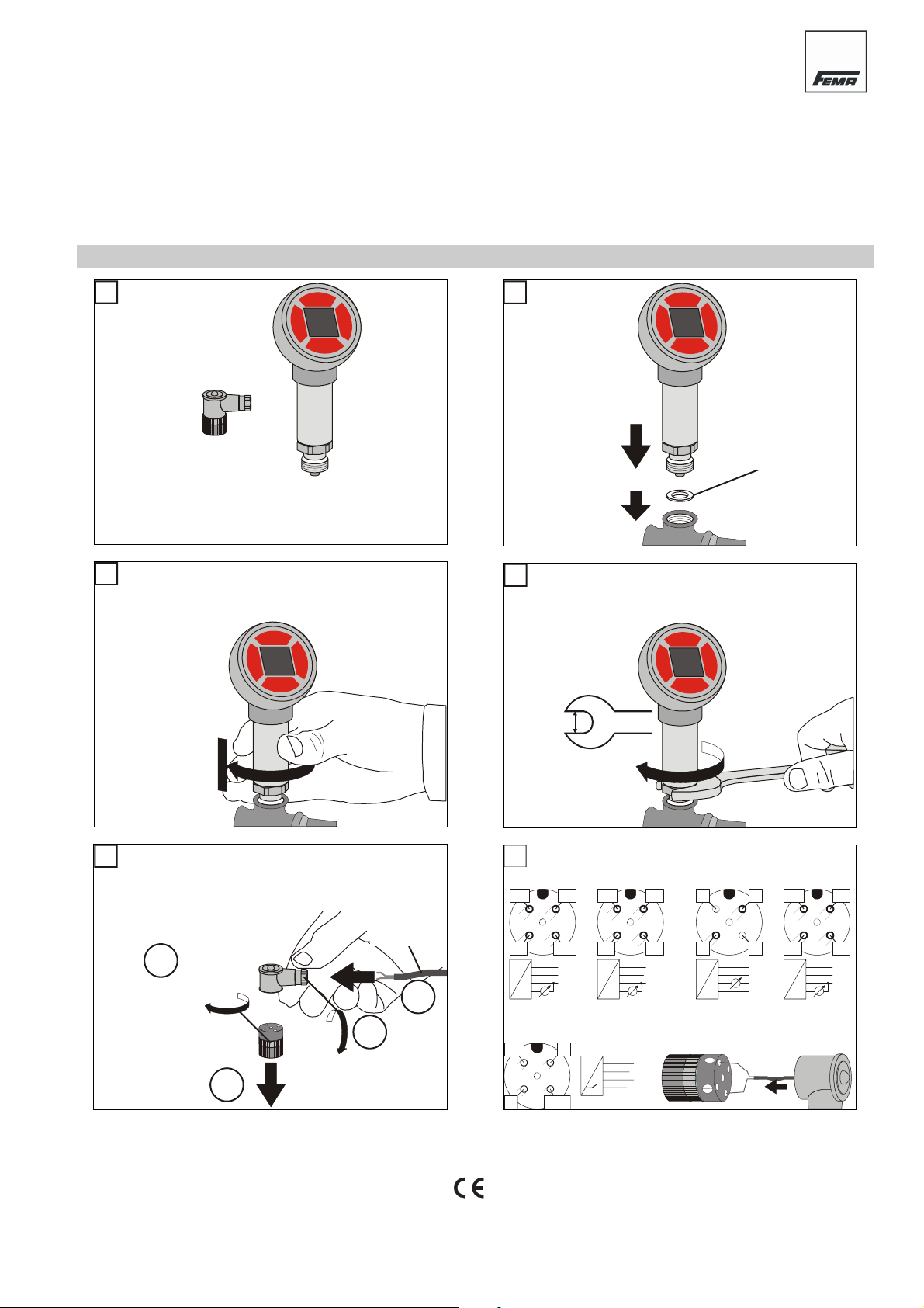
0
INCLUDED IN
DELIVERY
2
SCREW INTO PROCESS
connection, manually turn
approx. 3-4 times until snug.
3-4 X
IM LIEFERUMFANG
ENTHALTEN
IN PROZESSVERBINDUNG
einschrauben von Hand ca. 3-4
Drehungen bis fest.
1
BEFORE MOUNTING
Ensure line is without
pressure and cool.
VOR DER MONTAGE
Sicherstellen, dass
Leitung drucklos und
kuehl ist.
from customer
kundenseitig
3
TIGHTEN
(max. 20 Nm)
27 mm
FESTZIEHEN
(max. 20 Nm)
4
PREPARE FOR WIRING
Unscrew plug head. Loosen
cable gland. Insert cable.
A
3-4 X
B
ZUR VERDRAHTUNG
Stecker oeffnen. Verschraubung
loesen. Kabel einfuehren.
AWG 18
0,75 mm2
D
C
Attach wires to screw terminals.
PTH...
WARN
2
3
L-/
~
1
2
P
3
4
U/I
WARN
1
2
3
OC PNP
L-
WIRING
PTS...V3
WARN
L+/
~
1
4
U/I
OUT
L-/
L+/
~
WARN
L-/
~
PS...
L+
P
4
L+/
~
1
2
4
3
U
OUT
~
1
L+/
~
2
WARN
P
3
L-/
4
WARN
OC PNP
~
L+
L-
U
1
2
3
4
VERDRAHTUNG
Draehte verbinden.
PTS...A2
n.c.
2
L-
P
L+
1
4
3
n.c.
1
L+
2
n.c.
3
L-
I
4
n.c.
PTS...A3
WARN
2
3
L-/
~
1
2
P
3
I
4
L+/
~
1
4
I
OUT
L+/
~
WARN
L-/
~
® U.S Registered Trademark
Copyright © 2007 Honeywell Inc. • All Rights Reserved MU1B-0372GE51 R0207A
SMART DCM, SN (WITH HMI) - MOUNTING INSTRUCTIONS
A
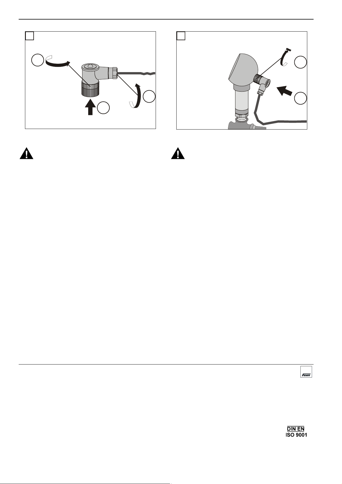
6
A
REASSEMBLY ZUSAMMENBAU
7
FASTEN PLUG STECKER BEFESTIGEN
B
3-4 X
C
INSTALLATION
WARNING
Before mounting or dismounting the unit, ensure that the
system is without pressure and without electrical current!
Process parts may be hot! Danger of personal injury due to
hot process parts. Always allow the unit (and attached pipes)
to cool down before mounting / dismounting the unit.
Mounting and Orientation
The device is mounted directly to the pipe via a G1/2"
(standard manometer) process connection (requiring a size
27 wrench). This process connection serves simultaneously
to fasten and secure the device in place. All mounting
orientations are permitted. Customer to provide gaskets.
Electrical Connection
All wiring must comply with applicable electrical codes and
local ordinances (e.g. in Germany, in accordance with VDE
regulations).
Pin Assignment of Plug
The plug is an A-coded, four-prong M12 plug.
Accessories
DMW Pressure surge reducer.
ST12-5-G Straight M12x1 plug.
INSTALLATION
VORSICHT
Vor dem Ein-/Ausbau Anlage drucklos machen und entleeren!
Spannungsfrei schalten!
Anlagenteile und Gerät können heiß sein! Verbrennungsgefahr! Gerät nur im abgekühlten Zustand montieren oder
abmontieren.
Montage und Ausrichtung
Das Gerät wird mittels Prozeßanschlußgewinde G½"
(Schlüsselweite 27) direkt in die Druckleitung geschraubt.
Damit wird gleichzeitig der Druckanschluß hergestellt und das
Gerät sicher in Position gehalten. Sämtliche Einbaulagen sind
zulässig. Notwendige Dichtungen bauseits bereithalten.
Elektrischer Anschluß
Die gesamte Verdrahtung muß gemäß den landesspezifischen Regeln und Normen durchgeführt werden (z.B.
in Deutschland nach VDE).
Kontaktbelegung des Steckers
Der Stecker ist ein A-codierter 4-poligen Stecker.
Zubehör
DMW Druckstoßminderer.
ST12-5-G Gerader M12x1 Stecker.
B
Manufactured for and on behalf of the Environmental and Combustion Controls Division of Honeywell Technologies Sàrl, Ecublens, Route du Bois 37, Switzerland by its Authorized Representative:
Fema Controls
Honeywell GmbH
P.O. Box 1254
D-71099 Schönaich
phone: (49) 7031-637-02
fax: (49) 7031-637-850
http:/honeywell.de/fema
Subject to change without notice. Printed in Germany
MU1B-0372GE51 R0107A
 Loading...