

Page 1
GENERAL
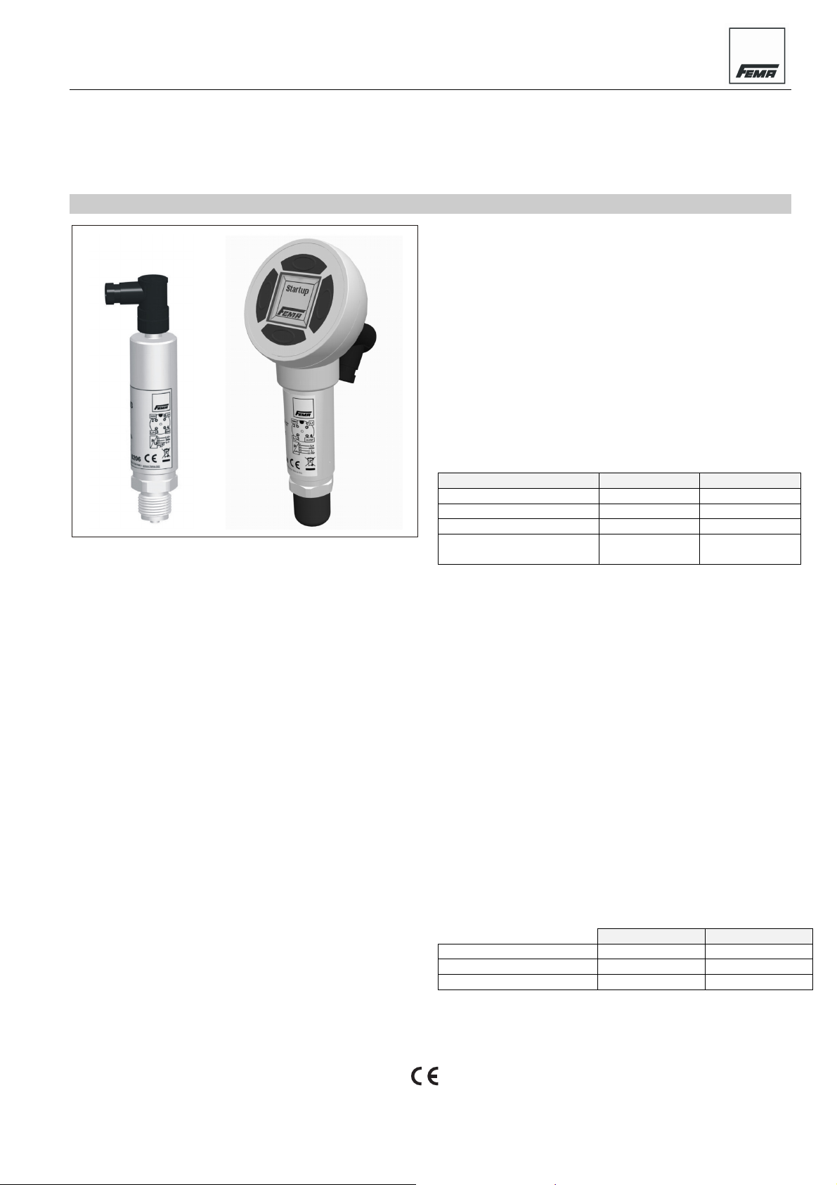
Honeywell FEMA's Smart DCM Electronic Pressure Switches
are microprocessor-controlled pressure measurement
devices for relative pressures of -1…+1 bar and 0…40 bar.
They are suitable for an extremely wide range of applications,
including the precision recording, monitoring, and control of
system pressures. They come complete with an angled
M12x1 plug and are screwed (G1/2”) directly into the line /
vessel to be monitored.
FEATURES
• Open-collector
• Configurable as min./max./window monitor
• Adjustable drop-in/drop-out delay
• Hysteresis defined by set-point and reset-point
• Backlit LCD graphical display (Human-Machine-Interface
models, only) can be swiveled for better readability;
display can be rotated in 90° steps by software
• Self-monitoring
TECHNICAL DATA
Materials
Parts in contact w/ medium Stainless steel (1.4571)
Chemical resistance 4C4 as per EN 60721-3-4
HMI PA66 GF25
Total weight 300 g without, 350 g with HMI
Storage temperature
Versions without HMI -40...+80 °C (≤ 16 bar)
-40...+100 °C (> 16 bar)
Versions with HMI -30...+80 °C
Smart DCM
ELECTRONIC PRESSURE SWITCHES
PRODUCT DATA
Ambient (operating) temperature and humidity
Versions without HMI -20...+80 °C
Versions with HMI -20...+70 °C
Humidity 0...95% r.h., non-condensing
Temperature of medium -20…+80 °C
Climate class
Indoors 4K4H as per EN 60721-3-4
Outdoors 3K8H as per EN 60721-3-3
Mechanical stability
Vibration 20 g as per IEC 68-2-6 (up to
2000 Hz)
Mechanical shock 100 g as per IEC 68-2-27
Device resistance / Accuracy (combined non-linearity,
hysteresis, and repeatability at 20 °C)
pressure range P ≤ 16 bar P > 16 bar
overpressure safety 2x P
burst pressure 4x P
sensor type piezo thin-film
accuracy
Pressure meas. range 0…40 bar, -1…1 bar
Cycle time 100 ms
Protection rating
Models without HMI IP67 as per EN 60529-2
Models with HMI IP65 as per EN 60529-2
EMC Conforms to EN 61326
Protection class 2 as per EN 61010
Process connection G1/2" external thread
Electrical connection 4-prong A-coded M12x1 plug
Power supply 18…35 Vdc, max. 30 mA
Main switch load 250 mA (overcurrent protection)
Switch output
Output, high level (min.) V
Output, low level (max.) GND plus 0.5 V
WARN output voltage passive: V
active: ≤ 0.5 V
Reaction time max. 300 ms
Span, offset, and long-term drift (within temperature
compensation range of 0…80 °C)
temp. effect on span ±0.3% FS / 10 K ±0.2% FS / 10 K
temp. effect on offset ±0.3% FS / 10 K ±0.2% FS / 10 K
long-term drift* ±0.3% FS / year ±0.2% FS / year
max. ±0.8% FS
±0.5% FS (typ.)
(without load)
SUPPLY
2x P
nominal
10x P
nominal
minus 2 V
SUPPLY
max. typical
nominal
nominal
max. ±1% FS
±0.6% FS (typ.)
- 2 V
® U.S Registered Trademark
Copyright © 2008 Honeywell Inc. • All Rights Reserved MU0B-0561GE51 R0608
Page 2
SMART DCM – PRODUCT DATA
MODEL KEY
PS Pressure Switch=
1 G½” pressure connection=
H HMI
=
S Standard
=
PS H
RV101 = ...1 bar (rel.)
-1
RB001 = 0...1 bar (rel.)
RB004 = 0...4 bar (rel.)
RB010 = 0...10 bar (rel.)
RB016 = 0...16 bar (rel.)
RB025 = 0...25 bar (rel.)
RB040 = 0...40 bar (rel.)
*Only in combination with non-HMI models.
1
S Service*=
1
SRB
00
Fig. 1. Overview of models
INSTALLATION
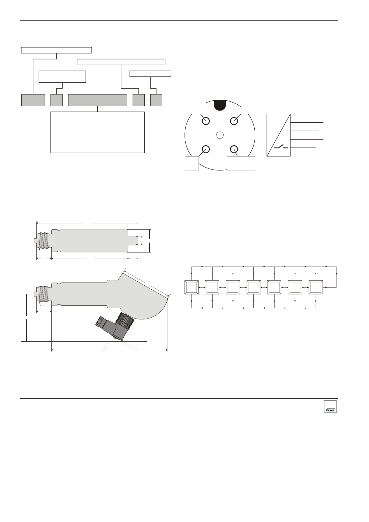
Dimensions
The geometry of the G1/2" connection conforms to DIN EN
837. See also Fig. 2.
G 1/2”
20
133
100
30
M12
13
Mounting and Electrical Wiring
The device is mounted directly to the pipe via a G1/2"
(standard manometer) process connection (size 27 wrench).
This process connection serves to fasten and secure the
device in place. All mounting orientations are permitted.
Pin Assignment of Plug
The plug is an A-coded, four-prong M12 plug (see Fig. 3).
WARN
2
1
L+
P
1
2
3
4
4
L-
3
OC PNP
Fig. 3. A-coded M12 plug
Electrical Protection
The pressure switches are protected against pole-reversal
(d.c. power) and miswiring. The switches' outputs are not
electrically isolated.
LCD (HMI-MODELS, ONLY)
HMI models feature a 19 X 19 mm LCD equipped with a
bicolor backlight (white = normal operation; red = fault mode).
LCD display information refresh is adjustable to between 1
and 9 seconds.
L+
WARN
L-
OC PNP
6
7
G 1/2”
20
64
PREVIOUS
-0.90
bar
Closed
MENU
ESCAPE ESCAPE ESCAPE ESCAPE ESCAPE ESCAPE
Set-pt.
5.00bar
MENU
PREVIOUS
NEXT
PREVIOUS
NEXT
PREVIOUS
Reset-pt.
4.00bar Window
Monitor Function
NEXT
MENU MENU MENU MENU MENU
PREVIOUS
NEXT
PREVIOUS
Drop in
NEXT
N.C.
Fig. 4. Menu structure (excerpt)
delay
PREVIOUS
Drop
out delay
NEXT
0s
NEXT
0s
Accessories
Included in delivery: M12x1 Angled plug.
152
Fig. 2. Dimensions (in mm)
Manufactured for and on behalf of the Environmental and Combustion Controls Division of Honeywell Technologies Sàrl, Ecublens, Route du Bois 37, Switzerland by its Authorized Representative:
Fema Controls
Honeywell GmbH
P.O. Box 1254
71099 Schönaich
Germany
phone: (49) 7031-637-02
fax: (49) 7031-637-850
http:/honeywell.de/fema
Subject to change without notice. Printed in Germany
MU0B-0561GE51 R0608
Optional:
• DMW Pressure surge reducer
• ST12-5-G Straight M12x1 plug.
Page 3

ALLGEMEINES
Die mikroprozessorunterstützten elektronischen Druckschalter der Baureihe Smart DCM von Honeywell FEMA
messen Relativdrücke von -1…+1 bar und 0…40 bar. Sie
sind bestens geeignet für vielfältige Einsatzbereiche, u.a. zur
genauen Erfassung, Überwachung und Regelung von
Systemdrücken. Der M12x1 Winkelstecker ist im Lieferumfang enthalten. Die Geräte werden direkt in die Druckleitung oder den Druckbehälter eingeschraubt (G1/2").
MERKMALE
• Open-Kollector
• Konfigurierbar als min./max./Fenster-Monitor
• Einstellbare Ein- und Ausschaltverzögerung
• Hysterese durch Stellpunkt und Rückstellpunkt definiert
• LCD-Anzeige (nur Human-Machine-Interface-Versionen),
zur besseren Ablesung schwenkbar, Anzeige per
Software in 90°-Schritten drehbar
• Selbstüberwachend
TECHNISCHE DATEN
Werkstoffe
Mediumberührte Teile Edelstahl (1.4571)
Chemische Beständigkeit 4C4 gemäß EN 60721-3-4
HMI PA66 GF25
Gesamtgewicht 300 g ohne, 350 g mit HMI
Lagertemperatur
Versionen ohne HMI -40...+80 °C (≤ 16 bar)
-40...+100 °C (> 16 bar)
Versionen mit HMI -30...+80 °C
Smart DCM
ELEKTRONISCHE DRUCKSCHALTER
PRODUKTDATEN
Umgebungstemperatur und -feuchtigkeit (bei Betrieb)
Versionen ohne HMI -20...+80 °C
Versionen mit HMI -20...+70 °C
Rel. Luftfeuchtigkeit 0...95%, nicht-kondensierend
Mediumtemperatur -20...+80 °C
Klimaklasse
Innenräume 4K4H gemäß EN 60721-3-4
Im Freien 3K8H gemäß EN 60721-3-3
Mechanische Festigkeit
Schwingungen 20 g gem. IEC 68-2-6 (bis
2000 Hz)
Mechan. Erschütterungen 100 g gemäß IEC 68-2-27
Druckbeständigkeit / Genauigkeit (kombinierte
Nichtlinearität, Hyst. und Reproduzierbarkeit bei 20 °C)
Druckbereich P ≤ 16 bar P > 16 bar
Überdruckbeständigkeit 2x P
Berstbeständigkeit 4x P
Fühlertyp Piezo Dünnfilm
Genauigkeit
Druckmeßbereich 0…40 bar, -1…1 bar
Taktzeit 100 ms
Schutzart
Versionen ohne HMI IP67 gemäß EN 60529-2
Versionen mit HMI IP65 gemäß EN 60529-2
EMV Gemäß EN 61326
Schutzklasse 2 gemäß EN 61010
Prozeßanschluß G1/2" Außengewinde
Elek. Anschluß 4-poliger M12x1-Stecker, "A"
Stromversorgung 18…35 Vdc, max. 30 mA
Hauptschaltlast 250 mA (gegen Überspannung
Schaltausgang
Ausg., oberer Wert (min.) V
Ausg., unterer Wert (max.) GND plus 0,5 V
WARN Ausg.-Spannung passiv: V
aktiv: ≤ 0,5 V
Antwortzeit max. 300 ms
Meßbereich, Kalibration und Langzeitdrift (innerhalb
Temperaturkompensationsbereich von 0…80 °C)
Temp.-Einfluß auf Meßb. ±0,3% FS / 10 K ±0,2% FS / 10 K
Temp.-Einfluß auf Kalib. ±0,3% FS / 10 K ±0,2% FS / 10 K
Langzeitdrift ±0,3% FS p.a. ±0,2% FS p.a.
max. ±0,8% FS
±0,5% FS (typ.)
(ohne Last)
geschützt)
VERSORG
2x P
nominal
10x P
nominal
minus 2 V
VERSORG
max. typisch
nominal
nominal
max. ±1% FS
±0,6% FS (typ.)
- 2 V
® U.S. eingetragene Handelsmarke
Urheberrechtlich geschützt © 2008 Honeywell Inc.
Alle Rechte Vorbehalten MU0B-0561GE51 R0608
Page 4

SMART DCM – PRODUKTDATEN
TYPENSCHLÜSSEL
PS Druckschalter=
1 G½” Druckanschluss=
H HMI
=
S Standard
=
PS H
RV101 = ...1 bar (rel.)
-1
RB001 = 0...1 bar (rel.)
RB004 = 0...4 bar (rel.)
RB010 = 0...10 bar (rel.)
RB016 = 0...16 bar (rel.)
RB025 = 0...25 bar (rel.)
RB040 = 0...40 bar (rel.)
*Nur in Verbindung mit Modellen ohne HMI.
1
S Service*=
1
SRB
00
Abb. 1. Typenübersicht
MONTAGE
Dimensionen
Die Geometrie des G1/2"- Anschlusses ist gemäß DIN EN
837. Siehe auch Abb. 2.
G 1/2”
20
G 1/2”
20
64
Abb. 2. Abmessungen (mm)
133
100
152
30
M12
13
6
7
Montage und Ausrichtung
Das Gerät wird mittels Prozeßanschlußgewinde G½"
(Schlüsselweite 27) direkt in die Druckleitung geschraubt.
Damit wird der Druckanschluß hergestellt und das Gerät
sicher in Position gehalten. Sämtliche Einbaulagen sind
zulässig.
Kontaktbelegung des Steckers
Der Stecker ist ein A-codierter 4-poliger Stecker (s. Abb. 3).
WARN
2
3
L-
Abb. 3. A-codierter M12-Stecker
L+
1
4
OC PNP
P
1
2
3
4
Elektrischer Schutz
Bei Betrieb mit Gleichstrom ist das Gerät gegen eine
Vertauschung der Strompolen geschützt. Die Ausgänge sind
nicht galvanisch isoliert.
LCD (nur Typen mit HMI)
Die HMI-Modelle sind mit einem 19 X 19 mm LCD ausgestattet mit zweifarbiger Hintergrundbeleuchtung (weiß =
Normalbetrieb; rot = Fehlbetrieb; 2-Leiter-Modelle ohne
Hintergrundbeleuchtung). Die Aktualisierungszeit der LCD
läßt sich zwischen 0 und 9 Sekunden einstellen.
PREVIOUS
-0.90
bar
Closed
MENU
ESCAPE ESCAPE ESCAPE ESCAPE ESCAPE ESCAPE
Set-pt.
5.00bar
MENU
PREVIOUS
NEXT
PREVIOUS
NEXT
PREVIOUS
Reset-pt.
4.00bar Window N.C.
Monitor Function
NEXT
MENU MENU MENU MENU MENU
PREVIOUS
NEXT
PREVIOUS
Drop in
NEXT
delay
PREVIOUS
NEXT
0s
Abb. 4. Menüstruktur (Auszug)
Zubehör
Im Lieferumfang enthalten: M12x1 Winkelstecker.
Optional:
• DMW Druckstoßminderer
• ST12-5-G Gerader M12x1 Stecker.
WARN
OC PNP
Drop
out delay
0s
L+
L-
NEXT
Hergestellt für und im Auftrag des Geschäftsbereichs Environmental and Combustion Controls der Honeywell Technologies Sàrl, Ecublens, Route du Bois 37, Schweiz in Vertretung durch:
Fema Controls
Honeywell GmbH
P.O. Box 1254
71099 Schönaich
Deutschland
Tel.: (49) 7031-637-02
Fax: (49) 7031-637-850
http:/honeywell.de/fema
Änderungen vorbehalten. Gedruckt in Deutschland
MU0B-0561GE51 R0608
 Loading...