

Page 1
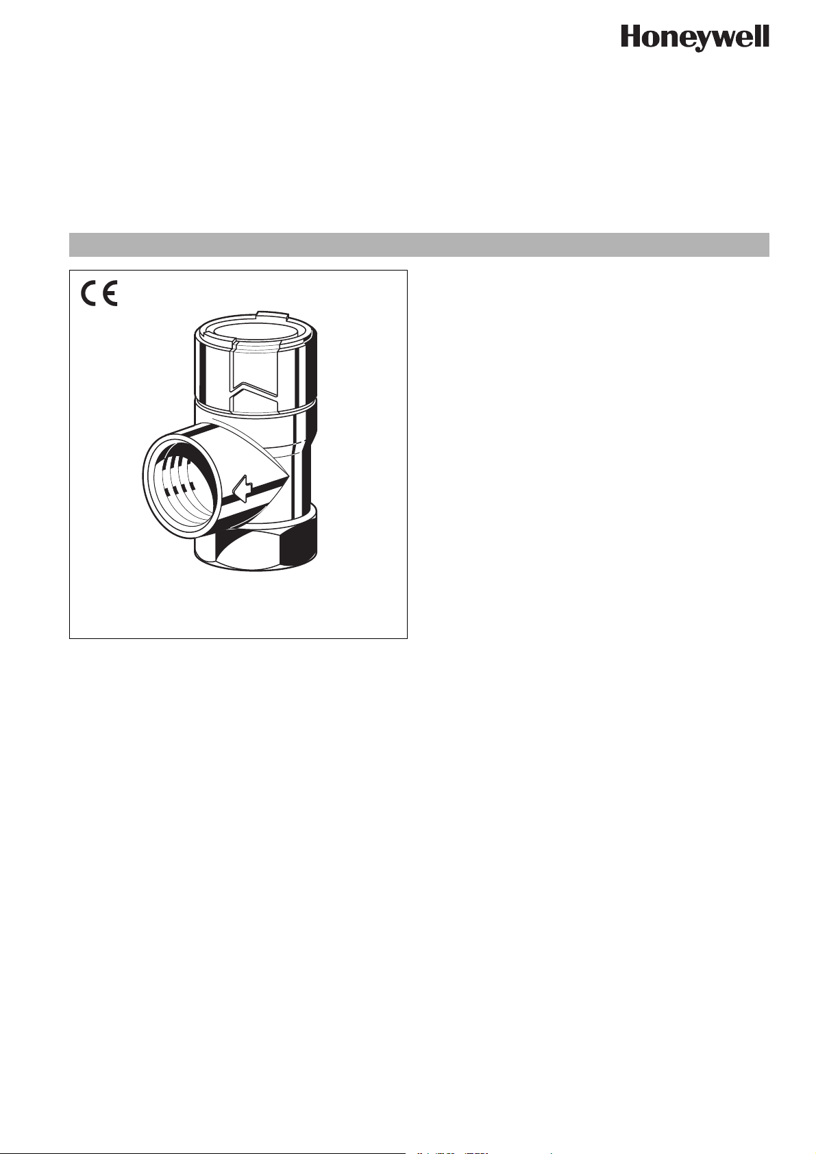
Construction
The safety valve comprises:
• Angled housing
• Adjustment spring
• Diaphragm
• Security cap with part label
Materials
• Brass housing
• Spring steel adjustment spring
• High grade synthetic material security cap
• Hot water resistant elastomer diaphragm
SM180
Diaphragm safety valve
for solar systems
Product specification sheet
Application
The membrane safety valves of this type are used as last safeguard for solar systems when the stipulated control and safety
devices fail. They must therefore be capable to discharge the
entire boiler output as steam in case of emergency.
In accordance with statutory requirements, the diaphragm safety
valve is preset to the required fixed set pressure by the manufacturer and is sealed with an embossed security cap marked with
the test badge and pressure rating to prevent unauthorised
tampering with the setting. Subsequent alteration of the setting is
not permitted and is impossible without destroying the security
cap. The preset pressure is embossed on the security cap.
Special Features
• Certified to Pressure Equipment Directive 97/23/EC, Reference No. CE 0036
• Standardised discharge connection
• With lifting device
• Protected against subsequent changing of the default
settings
Range of Application
To protect closed solar systems.
Medium Water or glycol-water mixture,
according to VDI 2035
Liquids of the fluid group 1 and 2 (pressure device
guideline, item 9) which do not affect the materials
used.
Technical Data
Installation position Horizontal with safety cap pointing up
Opening pressure Factory preset to 2.5, 3.0, 4.0, 6.0, 8.0 or
10.0 bar
Subsequent alteration of the setting is not
permitted and is impossible without
destroying the security cap
Operating temperature -20 °C...+160 °C
Connection size Internal thread on inlet
Internal thread on outlet
Valve size is defined by the size of the inlet connection
1
/2", 3/4",
1
/2", 3/4", 1"
EN0H-1368GE23 R0609 • Änderungen vorbehalten
www.honeywell.de/haustechnik 1
Page 2
SM180 Diaphragm safety valve
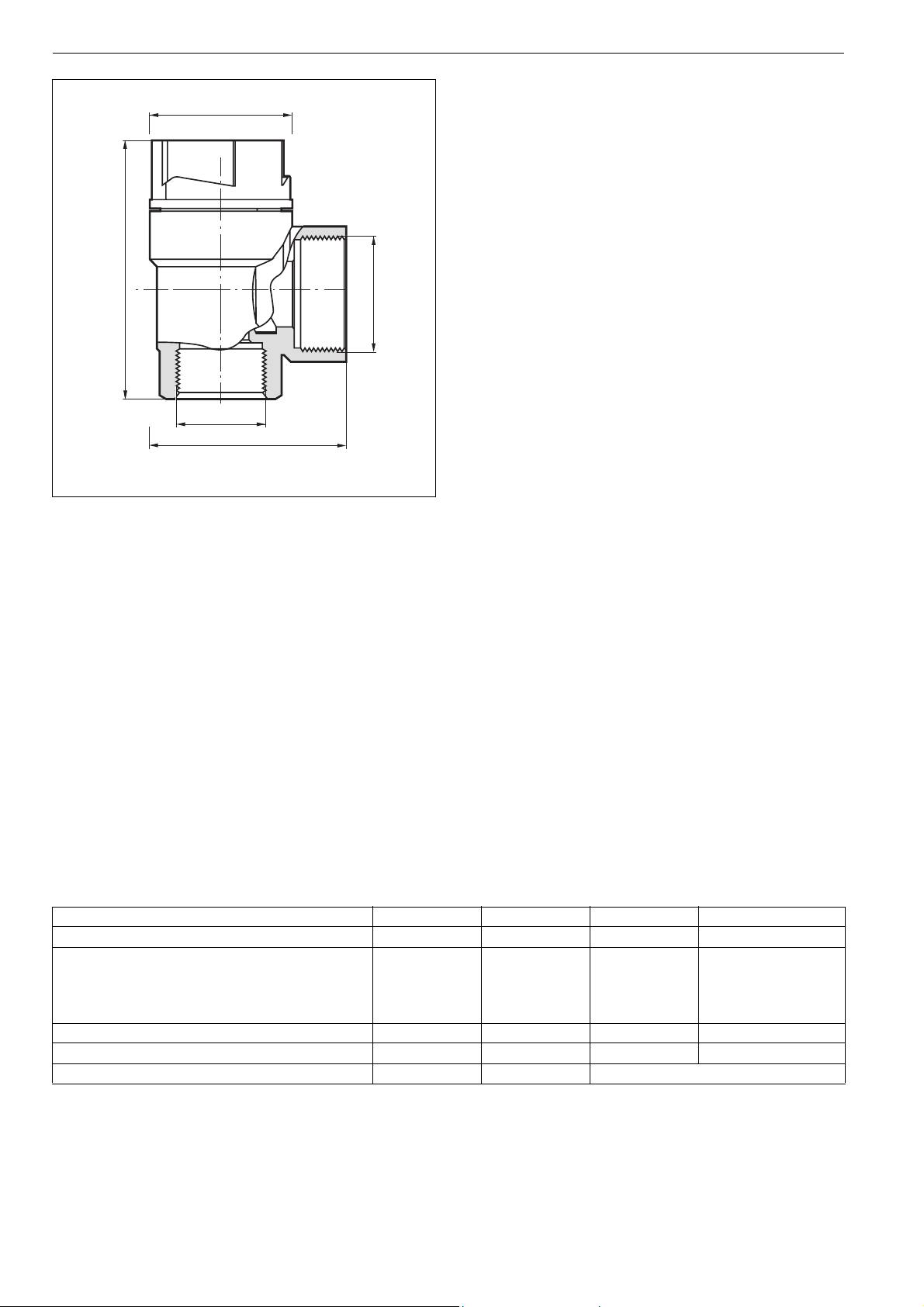
∅ D
o
H
REintritt
T
Method of Operation
Diaphragm safety valves of this type are directacting safety
valves in which the disc is pushed up by the pressure from the
system against a spring which is holding the valve closed. If the
opening force exceeds the force exerted by the spring, then the
valve disc is lifted off the valve seat and the valve discharges the
medium. In accordance with the requirements of the standard,
the full discharge capacity of the valve will be achieved when the
system pressure climbs to no more than 10% above the set
pressure of the valve. Full shutoff must be achieved if the system
pressure falls to below 80% of the nominal set pressure of the
valve. For valves rated up to 3.0 bar, the closing pressure can be
RAustritt
taken as 0.6 bar minimum.
Options
OS.-No. Set pres-
sure
SM180- 1/2ZA2.5 2.5 bar Rp
Connection size
Inlet
1
/2" IG Rp1/2" IG
Connection size
Outlet
SM180- 1/2ZA3.0 3.0 bar Rp1/2" IG Rp1/2" IG
1
SM180- 1/2ZA4.0 4.0 bar Rp
SM180- 1/2ZA6.0 6.0 bar Rp
/2" IG Rp1/2" IG
1
/2" IG Rp1/2" IG
SM180- 1/2ZA8.0 8.0 bar Rp1/2" IG Rp1/2" IG
1
SM180- 1/2ZA10.0 10.0 bar Rp
SM180- 1/2A2.5 2.5 bar Rp
/2" IG Rp1/2" IG
1
/2" IG Rp3/4" IG
SM180- 1/2A3.0 3.0 bar Rp1/2" IG Rp3/4" IG
1
SM180- 1/2A4.0 4.0 bar Rp
SM180- 1/2A6.0 6.0 bar Rp
/2" IG Rp3/4" IG
1
/2" IG Rp3/4" IG
SM180- 1/2A8.0 8.0 bar Rp1/2" IG Rp3/4" IG
1
SM180- 1/2A10.0 10.0 bar Rp
SM180- 3/4ZA2.5 2.5 bar Rp
/2" IG Rp3/4" IG
3
/4" IG Rp3/4" IG
SM180- 3/4ZA3.0 3.0 bar Rp3/4" IG Rp3/4" IG
3
SM180- 3/4ZA4.0 4.0 bar Rp
SM180- 3/4ZA6.0 6.0 bar Rp
SM180- 3/4ZA8.0 8.0 bar Rp
/4" IG Rp3/4" IG
3
/4" IG Rp3/4" IG
3
/4" IG Rp3/4" IG
SM180- 3/4ZA10.0 10.0 bar Rp3/4" IG Rp3/4" IG
3
SM180- 3/4A2.5 2.5 bar Rp
SM180- 3/4A3.0 3.0 bar Rp
/4" IG Rp1" IG
3
/4" IG Rp1" IG
SM180- 3/4A4.0 4.0 bar Rp3/4" IG Rp1" IG
3
SM180- 3/4A6.0 6.0 bar Rp
SM180- 3/4A8.0 8.0 bar Rp
SM180- 3/4A10.0 10.0 bar Rp
/4" IG Rp1" IG
3
/4" IG Rp1" IG
3
/4" IG Rp1" IG
Connection size Inlet R
Connection size Outlet R
1
/2" IG
1
/2" IG
3
/4" IG
3
/4" IG
1
/2" IG
3
/4" IG 1" IG
3
/4" IG
Dimensions (mm)
62
36
46
∅ D
H
o
T
60
33
32
62
33
46
60
33
46
Weight g 135 145 140 150
Maximum permissible heat input (kW) 50 100 50 100
TÜV Approval Nos. - - TÜV · SV · ..* - 2017 · 13 · SOL · p
..* valid Approval No.
Only the products with an outlet diameter larger than the inlet diameter are TÜV-certified.
2 www.honeywell.de/haustechnik
EN0H-1368GE23 R0609 • Änderungen vorbehalten
Page 3

Installation Example
SM180 Diaphragm safety valve
Installation Guidelines
• Mount the safety valve at the highest point of the heat generator or in its immediate vicinity on the flow line
• The installation must be carried out so that:
o no shut-off fittings, restrictions or strainers are located
Typical Applications
Membrane safety valves, according to their specification, are
installed in the return connection of solar systems.
The following is a typical application:
• closed solar systems
between safety valve and heat generator
o good access is provided for service and maintenance
o that the safety valve is positioned above the heat generator
o that between the safety valve and heat exchanger a max.
1 m long straight connection line with the size of the inlet
diameter is installed
• The safety valve must be mounted so that in its installed
condition no external forces act on it
• The discharge line must be performed to the size of the safety
valve outlet diameter and may not have more than 2 elbows
and or be longer than 2m
• The discharge line must be installed with an incline
Maintenance
We recommend conducting the measures listed below regularly and to enter into a maintenance agreement between operating
company and installation company.
Operation Interval Carried out by
Inspection Function check by verifying the response: While the system is operating,
briefly open the safety valve by turning the cap. After closing the cap the
valve must close again the backed up water drain completely.
Maintenance If a malfunction is detected, a repair can be attempted by opening and
EN0H-1368GE23 R0609 • Änderungen vorbehalten
closing the cap several times. A replacement is necessary if this action
is not successful.
Every six months User or specialist
Annually Specialist
www.honeywell.de/haustechnik 3
Page 4

SM180 Diaphragm safety valve
Automation and Control Solutions
Honeywell GmbH
Hardhofweg
D-74821 Mosbach
Phone: (49) 6261 810
Fax: (49) 6261 81309
http://europe.hbc.honeywell.com
www.honeywell.com
Manufactured for and on behalf of the
Environmental and Combustion Controls Division
of Honeywell Technologies Sàrl, Rolle, Z.A. La
Pièce 16, Switzerland by its Authorised Representative Honeywell GmbH
EN0H-1368GE23 R0609
Subject to change without notice
© 2009 Honeywell GmbH
 Loading...