

Page 1
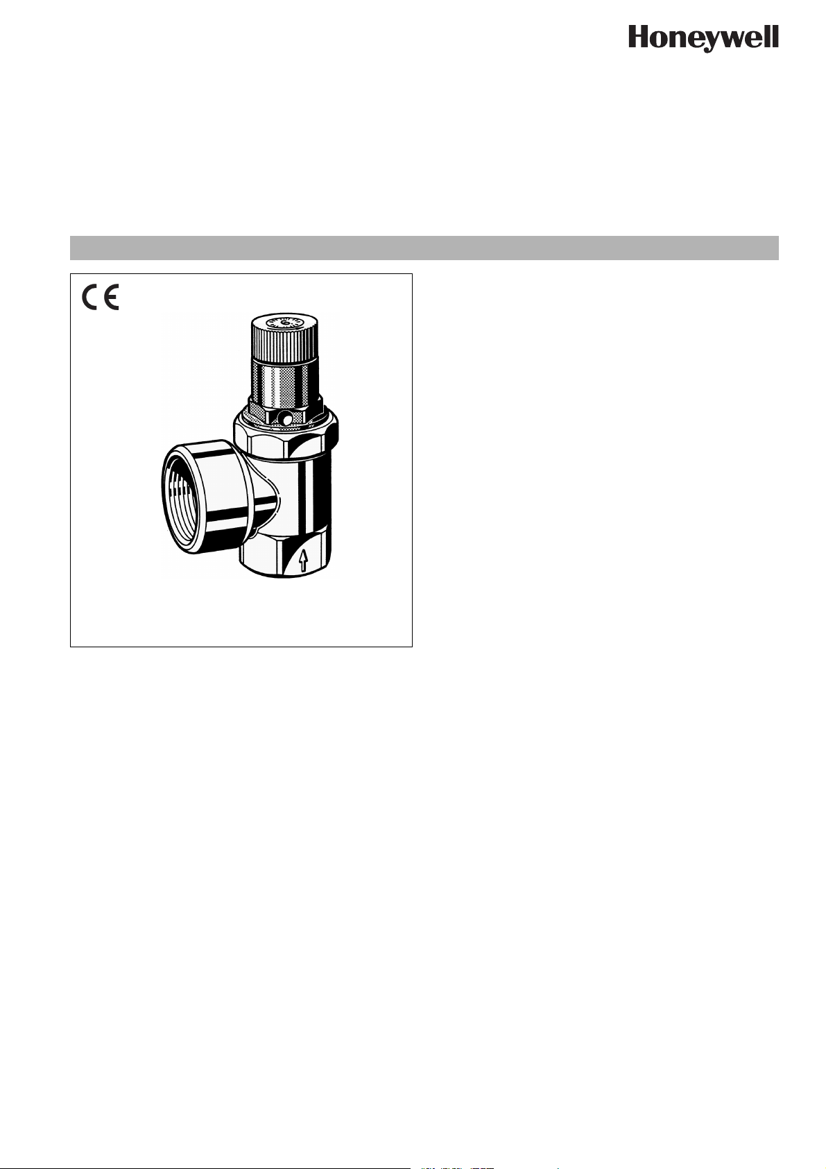
SM152
Diaphragm safety valve
for closed water heaters
Product specification sheet
Application
Diaphragm-type safety valves of this type are used to protect
pressurised water heaters according to the require-ments of DIN
4753, Part 1 and DIN 1988.
In accordance with statutory requirements, the diaphragm safety
valve is preset to the required fixed set pressure by the manufacturer and is sealed with an embossed security cap marked with
the test badge and pressure rating to prevent unauthorised
tampering with the setting. Subsequent alteration of the setting is
not permitted and is impossible without destroying the security
cap. The preset pressure is embossed on the security cap.
Special Features
• Replacement insert tested to TRD 721
• Easy venting
• Replacement insert makes servicing simple
• Meets KTW recommendations for potable water
• Certified to Pressure Equipment Directive 97/23/EC, Reference No. CE 0035
• Standardised discharge connection
Construction
The safety valve comprises:
• Angled housing
• Safety valve exchange insert, approved and comprising
screw-in section with hexagon, spring bonnet, security cap
with certification and rating plate, venting knob, sealing disc,
diaphragm, setting spring
Materials
• Brass housing
• High grade synthetic material screw-in section (for up to 6.0
bar set pressure) or brass (for set pressures above 6.0 bar)
• High-quality synthetic material spring bonnet
• High grade synthetic material security cap
• High grade synthetic material venting knob
• Hot water resistant elastomer seal disc
• Hot water resistant elastomer diaphragm
• Spring steel adjustment spring
EN0H-1301GE23 R0807 • Subject to change
Range of Application
For closed water heaters in compliance with DIN 4753, Part 1 and
DIN 1988
Tested to TRD 721 for pressure range 1.0 bar to 10.0 bar.
Medium Water
Technical Data
Installation position Horizontal with spring bonnet upwards
Opening pressure Set by manufacturer at 6.0, 8.0 or 10.0 bar
Special settings between 1.0 bar and
10.0 bar are also available
Subsequent alteration of the setting is not
permitted and is impossible without
destroying the security cap
Operating temperature
Connection size
Valve size is defined by the size of the inlet connection
Max. 95 °C
1
/2" - 11/4"
www.honeywell.com 19
Page 2
SM152 Diaphragm safety valve
Method of Operation
Diaphragm safety valves of this type are directacting safety
valves in which the disc is pushed up by the pressure from the
system against a spring which is holding the valve closed. If the
opening force exceeds the force exerted by the spring, then the
valve disc is lifted off the valve seat and the valve discharges the
medium. In accordance with the requirements of the standard,
the full discharge capacity of the valve will be achieved when the
system pressure climbs to no more than 10% above the set
pressure of the valve. Full shutoff must be achieved if the system
pressure falls to below 80% of the nominal set pressure of the
valve. For valves rated up to 3.0 bar, the closing pressure can be
taken as 0.6 bar minimum.
Options
SM152- … AA = Not chrome plated, 6.0 bar
SM152- … AB = Not chrome plated, 8.0 bar
SM152- … AC = Not chrome plated, 10.0 bar
SM152- … BA *= Chrome plated, 6.0 bar
SM152- … BC *= Chrome plated, 10.0 bar
SM152- … Z = special setting, when ordering, be sure to indi-
cate set pressure
* 1/2" connection size only
Special Versions available on request
Connection size
Connection size Inlet R
Connection size Outlet R
1
/2"
3
/4"1"1
3
/4"1"1
1
/4"1
1
/4"
1
/2"
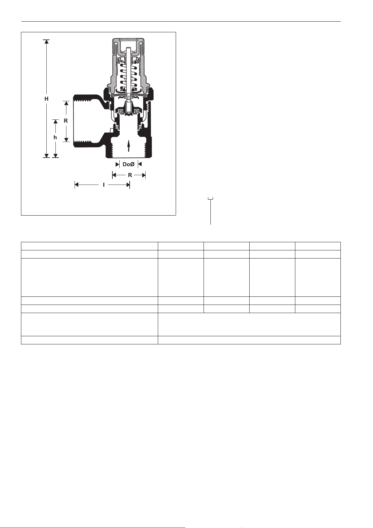
Dimensions (mm)
∅ D
H
h
I
o
87
23
36
14
91
28
42
14
123
40
50
18
130
47
55
18
For water heaters with capacity (litres) up to 200 up to 1000 up to 5000 over 5000
Maximum permissible heat input (kW) 75 150 250 2200
TÜV Approval Nos. TÜV · SV · ..* - 617 · (
TÜV · SV · ..* - 616 · 1
TÜV · SV · ..* - 700 · (
1
/2"+3/4", 1") · W · p
1
/4" · W · 2200 · p
1
/2"+3/4")·W·p
(6-10 bar)
(1-10 bar)
(1-6 bar)
..* valid Approval No.
20 www.honeywell.com
EN0H-1301GE23 R0807 • Subject to change
Page 3

Installation Example
SM152 Diaphragm safety valve
Installation Guidelines
• Safety valve must be installed in the cold water supply pipework before the water heater
• The installation must be carried out so that:
o There are no shutoff valves or fittings, narrowing of the
pipework or strainers between the water heater and the
safety valve
Typical Applications
Diaphragm safety valves are installed in accordance with their
specification upstream of water heaters.
The following are some typical applications:
• Central hot water supply systems
• Hot water storage units
o Good access is provided for service and maintenance
o The safety valve is fitted above the top of the water heater
to avoid the need for draining down when exchanging the
safety valve insert
• If there is no drainage facility in the room where the heater is
installed, then the safety valve may be fitted in an adjacent
area. DIN 1988, part 2 is to be observed
Maintenance
In accordance with DIN 1988, Part 8, the following operations should be carried out regularly. A planned maintenance scheme is
recommended.
Operation Interval Carried out by
Inspection Safety valve: Check operation as follows: With the system operating,
Every six months User or specialist
open the venting device. The resulting water flow must fully drain away.
When the ventil is released,the valve must fully close.
Maintenance Safety valve: If a malfunction occurs,this may be cured by repeated
Annually Specialist
manual opening and closing of the valve. If this method does not
succeed, then an overhaul of the valve will be necessary.
EN0H-1301GE23 R0807 • Subject to change
www.honeywell.com 21
Page 4

SM152 Diaphragm safety valve
Spare Parts
Diaphragm Safety Valves SM152, from 1981 onwards
No. Description Dimension Part No.
1 Safety valve insert
Approval No. - TÜV · SV · ..* - 617 -
1
/2"+3/4"·W·p
Approval No. - TÜV · SV · ..* - 617 - 1" · W · p
1
Approval No. - TÜV · SV · ..* - 700 Approval No. - TÜV · SV · ..* - 700 - 1" · W · p
6.0 bar
1
/2" A152-1/2AA
3
/4" A152-3/4AA
1
/2"+3/4"·W·p
1" A152-1AA
8.0 bar
1
/2" A152-1/2AB
3
/4" A152-3/4AB
1" A152-1AB
10.0 bar
1
/2" A152-1/2AC
3
/4" A152-3/4AC
1" A152-1AC
..* valid Approval No.
2 Safety valve insert
with chrome plated
bodyl
Approval No. - TÜV · SV · ..* - 617 8 bar
10 bar
1
/2" A152-1/2BB
3
/4" A152-3/4BB
1
/2" A152-1/2BC
3
/4" A152-3/4BC
1
/2"+ 3/4"·W·p
..* valid Approval No.
3 Safety valve insert
Approval No. - TÜV · SV · ..* - 616 - 1
6 bar 1
8 bar 1
10 bar 1
1
/4" A160-11/4AA
1
/4" A160-11/4AB
1
/4" A160-11/2AC
..* valid Approval No.
1
/4" · W · (2200) · p
Automation and Control Solutions
Honeywell GmbH
Hardhofweg
D-74821 Mosbach
Phone: (49) 6261 810
Fax: (49) 6261 81309
http://europe.hbc.honeywell.com
www.honeywell.com
Manufactured for and on behalf of the
Environmental and Combustion Controls Division
of Honeywell Technologies Sàrl, Ecublens, Route
du Bois 37, Switzerland by its Authorised Representative Honeywell GmbH
EN0H-1301GE23 R0807
Subject to change without notice
© 2007 Honeywell GmbH
 Loading...