


SLN 700
SmartLine Le vel Tran sm it ter
Non-Contact Radar
User’s Manual
34-SL-25-13
Revision 1
October 2020
Revision 1 SLN 700 SmartLine NCR Level Transmitter User’s Manual Page i

Copyrights, Notices and Trademarks
© Copyright 2020 by Honeywell International
Revision 1.0, October 2020
While the information in this document is presented in good faith and believed to be
accurate, Honeywell disclaims any implied warranties of merchantability and fitness for a
particular purpose and makes no express warranties except as may be stated in the written
agreement with and for its customers. In no event is Honeywell liable to anyone for any
indirect, special, or consequential damages. The information and specifications in this
document are subject to change without notice.
Honeywell, TDC3000, SFC, SmartLine, PlantScape, Experion PKS, and TotalPlant are
registered trademarks of Honeywell International Inc. Other brand or product names are
trademarks of their respective owners.
Honeywell Process Solutions
1250 W Sam Houston Pkwy S
Houston, TX 77042
Page ii SLN 700 SmartLine NCR Level Transmitter User’s Manual Revision 1

About This Manual
Version
Date released
History
Rev. 1.0
October 2020
First release
This manual is a detailed how to reference for installing, wiring, configuring, starting up,
operating, maintaining, calibrating, and servicing Honeywell’s family of SLN 700
SmartLine Non-Contact Radar Level Transmitters.
For details on the HART
Option User’s Manual, Document #34-SL-25-16.
The configuration of your Transmitter depends on the mode of operation and the options
selected for it with respect to operating controls and mechani ca l instal lat ion. Thi s manual
provides detailed procedures to assist first-time users, and it further includes keystroke
summaries, where appropriate, as quick reference or refreshers for experienced personn el.
To digitally integrate a Transmitter with one of the following systems:
• For the Experion PKS, you will need to supplement the information in this document
with the data and procedures in the Experion Knowledge Builder.
• For Honeywell’s TotalPlant Solutions (TPS), you will need to supplement the
information in this document with the data in the PM/APM SmartLine Transmitter
Integration Manual, which is supplied with the TDC 3000 book set. (TPS is the
evolution of the TDC 3000).
protocol, users are referred to the SLN 700 Series HART
Revision History
SLN 700 SmartLine Level Non-Contact Radar Transmitter User’s Manual,
Document #34-SL-25-13.
Revision 1 SLN 700 SmartLine NCR Level Transmitter User’s Manual Page iii
References
hfs-tac-support@honeywell.com
The following list id entifies publ ications that m ay contain inform a tion re levant to the
information in this document.
• SLN 700 SmartLine Non-Contact Radar Level Transmitter HART Option Manual,
#34-SL-25-16
• SLN 700 SmartLine NCR Level Transmitter Specification, #34-SL-03-06
• SLN 700 SmartLine NCR Quick Start Guide (in the box), #34-SL-25-14
Support and Contact Information
For Europe, Asia Pacific, North and South America contact details, refer to the back page
of this manual or the appropriate Honeywell Support web site:
Honeywell Corporate www.Honeywellprocess.com
Honeywell Process Solutions hfs-tac-support@honeywell.com
Honeywell SmarLine Level https://www.honeywellprocess.com/smartline-level-
Telephone and Email Contacts
transmitter.aspx
Area Organization Phone Number
United States and
Canada
Global Email
Support
Honeywell Inc.
Honeywell Process
Solutions
1-800-343-0228 Customer Service
1-800-423-9883 Global Technical Support
Page iv SLN 700 SmartLine NCR Level Transmitter User’s Manual Revision 1
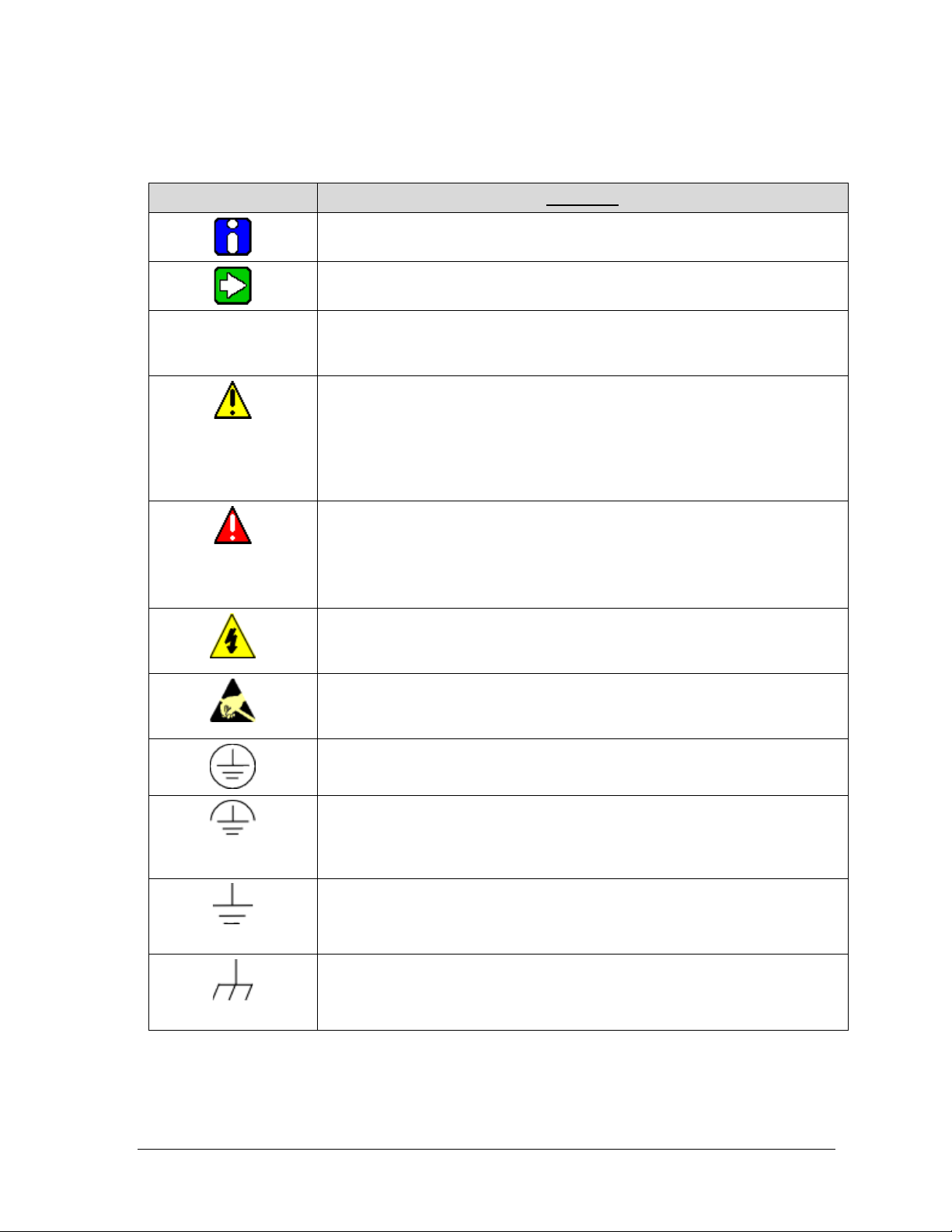
Symbols Descriptions and Definitions
The following symbols may appear in this document.
Symbol Definition
ATTENTION: Identifies information that requires special consideration.
TIP: Identifies advice or hints for the user, often in terms of performing a
task.
CAUTION Indicates a situation which, if not avoided, may result in equipment or
work (data) on the system being damaged or lost, or may result in the
inability to properly operate the process.
CAUTION: Indicates a potentially hazardous situation which, if not
avoided, may result in minor or moderate injury. It may also be used to
alert against unsafe practices.
CAUTION symbol on the equipment refers the user to the product manual
for additional information. The symbol appears next to required
information in the manual.
WARNING: Indicates a potentially hazardous situation, which, if not
avoided, could result in serious injury or death.
WARNING symbol on the equipment refers the user to the product
manual for additional information. The symbol appears next to required
information in the manual.
WARNING, Risk of electrical shock: Potential shock hazard where
HAZARDOUS LIVE voltages greater than 30 Vrms, 42.4 Vpeak, or 60
VDC may be accessible.
ESD HAZARD: Danger of an electro-static discharge to which equipment
may be sensitive. Observe precautions for handling electrostatic sensitive
devices.
Protective Earth (PE) terminal: Provided for connection of the protective
earth (green or green/yellow) supply system conductor.
Functional earth terminal: Used for non-safety purposes such as noise
immunity improvement. Note: This connection shall be bonded to
Protective Earth at the source of supply in accordance with national local
electrical code requirements.
Earth Ground: Functional earth connection. Note: This connection shall
be bonded to Protective Earth at the source of supply in accor danc e with
national and local electrical code requirements.
Chassis Ground: Identifies a connection to the chassis or frame of the
equipment shall be bonded to Protective Earth at the source of supply in
accordance with national and loc al electrical code requirements.
Revision 1 SLN 700 SmartLine NCR Level Transmitter User’s Manual Page v
The Factory Mutual® Approval mark means the equipment has been
rigorously tested and certified to be reliable.
The Canadian Standards mark means the equipment has been tested
and meets applicable standards for safety and/or performance.
The Ex mark means the equipment complies with the requirements of the
European standards that are harmonized with the 2014/68/EU Directive
(ATEX Directive, named after the French "ATmosphere EXplosible").
Page vi SLN 700 SmartLine NCR Level Transmitter User’s Manual Revision 1

Contents
1 Introduction .......................................................................................................... 1
1.1 Overview ................................................................................................................................. 1
1.2 Transmitter Models ................................................................................................................. 1
1.3 Transmitter Components ........................................................................................................ 1
1.3.1 Overview of components .................................................................................................... 1
1.3.2 Electronics .......................................................................................................................... 2
1.3.3 Process Connector ............................................................................................................. 2
1.4 Communicating with the Transmitter ...................................................................................... 3
1.5 SLN 700 Transmitter Label ..................................................................................................... 3
1.6 Transmitter Model Number Description .................................................................................. 4
1.7 Safety Certification Information .............................................................................................. 4
2 Radar Level Measurement ................................................................................... 5
2.1 Overview ................................................................................................................................. 5
2.2 Theory of Operation ................................................................................................................ 5
3 Mounting .............................................................................................................. 6
3.1.1 Moisture-proof ..................................................................................................................... 7
3.1.2 Installation position ............................................................................................................. 8
3.1.3 Nozzle installations ........................................................................................................... 10
3.1.4 Correct and incorrect Installation position ........................................................................ 11
3.1.5 Installations with Agitation ................................................................................................ 12
4 Transmitter Installation ....................................................................................... 13
4.1 Supply voltage ...................................................................................................................... 13
4.2 Installation of connecting cables ........................................................................................... 14
4.2.1 General introduction ......................................................................................................... 14
4.3 Wiring mode .......................................................................................................................... 14
4.3.1 2-Wire ............................................................................................................................... 14
4.4 Hazardous Location – Intrinsic Safety .................................................................................. 15
5 Operating the Transmit ter .................................................................................. 17
5.1 Functions of keys .................................................................................................................. 17
6 Maintenance ...................................................................................................... 36
6.1 Configuration method ........................................................................................................... 36
6.1.1 Configuration with Display ................................................................................................ 36
6.1.2 Configuration .................................................................................................................... 37
Revision 1 SLN 700 SmartLine NCR Level Transmitter User’s Manual Page vii

6.2 Procedures ............................................................................................................................ 38
6.2.1 Output Check Procedures ................................................................................................. 38
6.2.2 Constant Current Source Mode Procedure (Loop Test) ................................................... 38
6.2.3 Error Codes: ...................................................................................................................... 39
Glossary ................................................................................................................... 40
List of Figures
Figure 1-1 Components of the Level transmitter ................................................................................... 1
Figure 1-2: SLN 700 Transmitter label example ................................................................................... 3
Figure 1-3: Standard SLN 700 Model Number ..................................................................................... 4
Figure 3-1: Graphical illustration ........................................................................................................... 6
Figure 3-2: Moisture-proof diagram ...................................................................................................... 7
Figure 3-3: Installation position, >200 mm ........................................................................................... 8
Figure 3-4: Conical vessel installation ................................................................................................... 9
Figure 3-5: nozzle specifications diagram ........................................................................................... 10
Figure 3-6: Correct and incorrect installation position ........................................................................ 11
Figure 3-7: Correct and incorrect installation position ........................................................................ 11
Figure 3-8: Installation of reflecting plate ........................................................................................... 12
Figure 3-9: Agitation ............................................................................................................................ 12
Figure 4-1: Maximum Loop Resistance (Ω) ........................................................................................ 13
Figure 4-2: 2-wire wiring for HART ................................................................................................... 14
Figure 4-3: Intrinsically Safe Wiring ................................................................................................... 16
Figure 5-1: Instrument panel 4-key ...................................................................................................... 17
Figure 5-2: Representation of an echo curve defining the Echo Threshold and the Envelope Offset
quantities. ............................................................................................................................................. 35
Figure 6-1: Connect via HART hand-held ........................................................................................... 37
List of Tables
Table 1-1: Process Connector ................................................................................................................ 2
Table 3-1: Minimal distance to tank wall .............................................................................................. 8
Table 3-2: nozzle specifications table .................................................................................................. 10
Table 4-1: Maximum Loop Resistance (Ω) ......................................................................................... 13
Table 4-2: Hazardous Location Ratings ............................................................................................... 15
Table 4-3: Intrinsic Safety Entity Parameters ...................................................................................... 15
Table 4-4: Process Temperature Vs Tem pera tur e Class ...................................................................... 15
Table 5-1: Keys of LCD ...................................................................................................................... 17
Table 5-2: Display Menu Tree Basic Settings, Display and Diagnostics ............................................ 32
Table 5-3: Display Menu Tree Advanced Settings and System .......................................................... 34
Page viii SLN 700 SmartLine NCR Level Transmitter User’s Manual Revision 1
1.1 Overview
The SLN 700 SmartLine 80 GHz Non-Contact Radar transmitter is an electron ic i nstrument
designed to measure levels of liquid and solid materials. Non-Contact Radar (NCR) transmitters
use Frequency Modulated Continuous Wave (FMCW) radar signals that are reflected by the
material to be measured. The difference in frequency between the received and transmitted
signal is directly proportional to the distance to the liquid and can be measured with high
precision. Its small beam angle and small antenna size makes it easy to install. In com parison to
other level measurement technologies, NCR provides a highly-accurate, cos t-effective, reliable
measurement in applications where Guided Wave Radar (GWR) are not suitable.
1.2 Transmitter Models
The SLN 700 SmartLine 80 GHz NCR transmitter is available as a part of the family of
SLN700L models for liquid and SLN700S for solid applications. The pressure and temperature
range is -40 to 200°C/-1 to 40 bar for both, and each model is available with a range of flange or
threaded antenna, lens diameters, process connection, and accessories to suit most applications.
1 Introduction
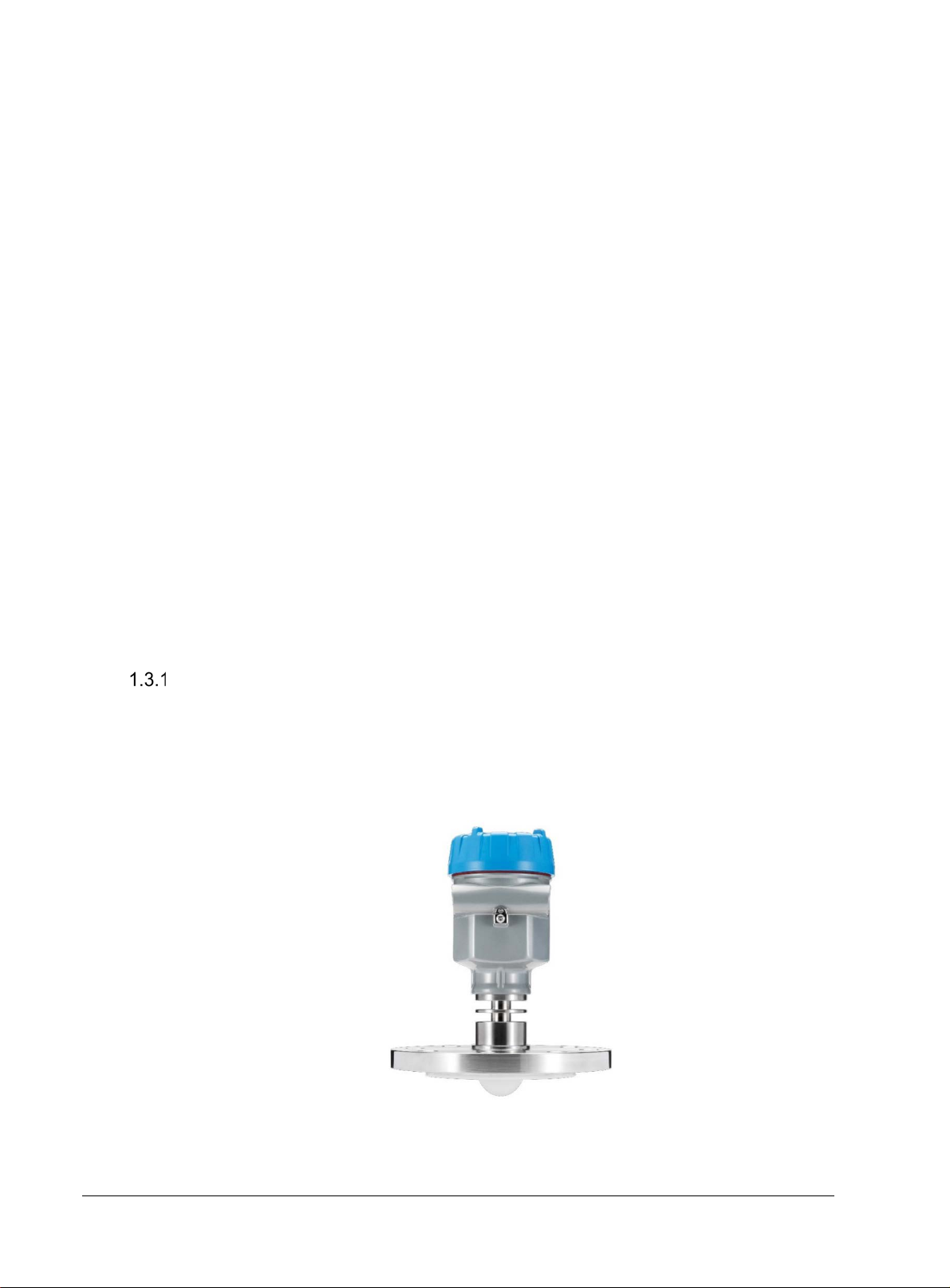
1.3 Transmitter Components
Overview of components
As shown in Figure 1-1, the transmitter consists of:
• Electronics housing containing the core measurement module and optional display
module
• Process connection
• RF antenna
Figure 1-1 Components of the Level transmitter
Revision 1 SLN 700 SmartLine NCR Level Transmitter User’s Manual Page 1
Series
Medium
Applications
Process
connections
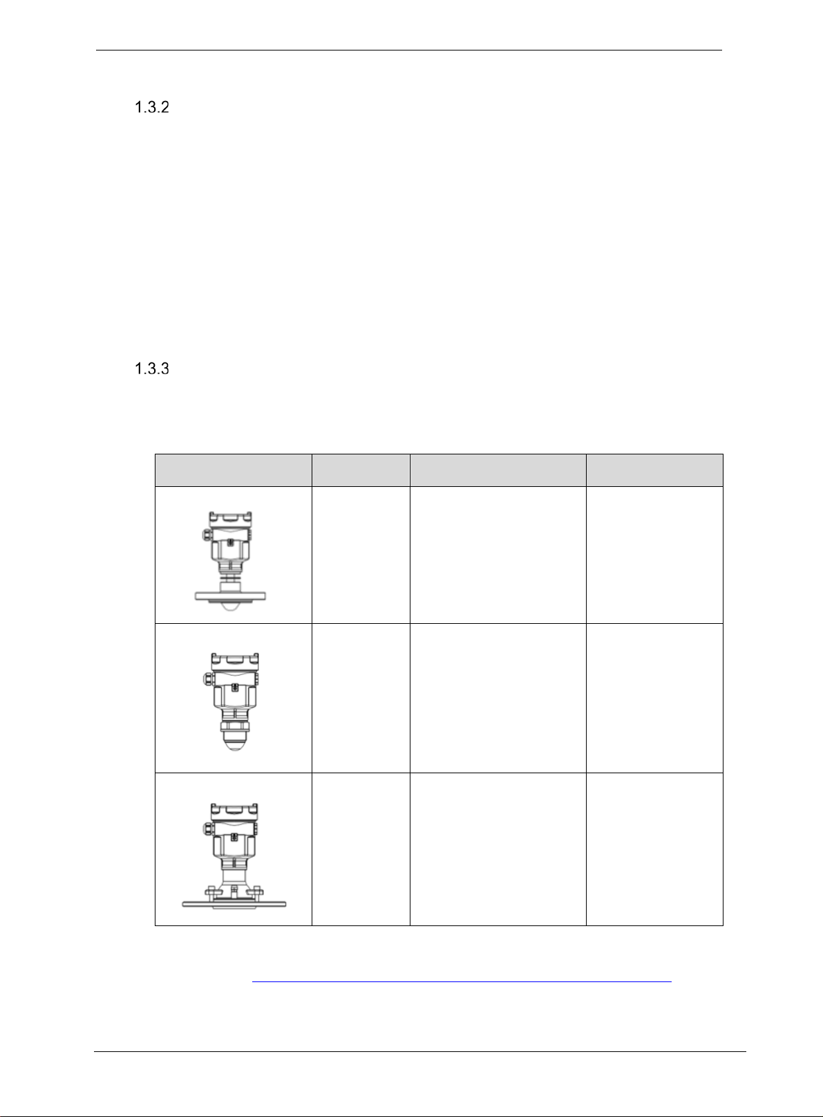
82 Series
Liqid
Strong corrosive liquid
Flangeoptions
83 Series
Liquid
Strong corrosive or
Thread options
87 Series
Solid
Storage vessel/process
Flange options
Electronics
The Electronics consists of 2 distinct modules; core measurement electronics module and an
optional display module. Both are replaceable in the field.
To make changes to the transmitter setup or configuration without the use of an external device
such as a handheld or PC, an optional 4-Button interface is available.
The Optional Display module has the following features. (needs to be updated)
• Echo stem plot for checking measurement accuracy
• Standard and custom engineering units
• Diagnostic alerts and diagnostic messaging
• English and Chinese language options
Process Connector
The 80 GHz non-contact radar transmitter has 3 different series of products and associated
process connections.
Table 1-1: Process Connector
vapors o foam
pressure resistant liquid
vessel or high dust
applications
Page 2 SLN 700 SmartLine NCR Level Transmitter User’s Manual Revision 1
For list of all options and accessories please refer to the product specifications, which is
available, here: https://www.honeywellprocess.com/smartline-level-transmitter.aspx.
1.4 Communicating with the Tr a ns mi t t er
Level monitoring is possible through either the analog current (4-20 mA) or HART. It is possible
to configure a transmitter using HART
©
protocol or using the four-button interface and display.
Refer to manual 34-SL-25-16, SLN700 NCR HART Option Manual for details on available
HART commands
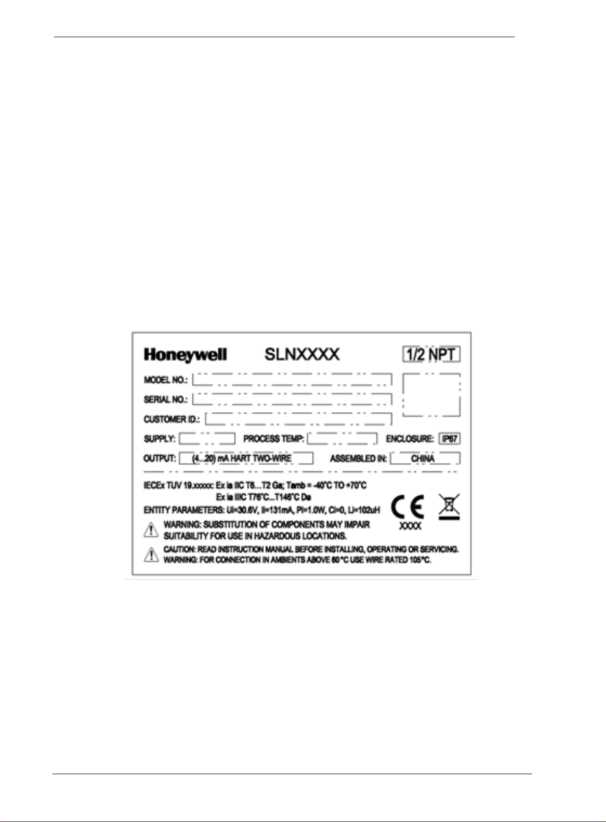
1.5 SLN 700 Transmitter Label
The transmitter label is mounted on the side of the electronics housing
(see Figure 1-2) and lists the following properties:
• Model number
• Physical con fig u ra tio n
• Power supply voltage
• Maximum working pressure rating
• Certification, if ordered (SIL and CRN)
Figure 1-2: SLN 700 Transmitter label example
Revision 1 SLN 700 SmartLine NCR Level Transmitter User’s Manual Page 3
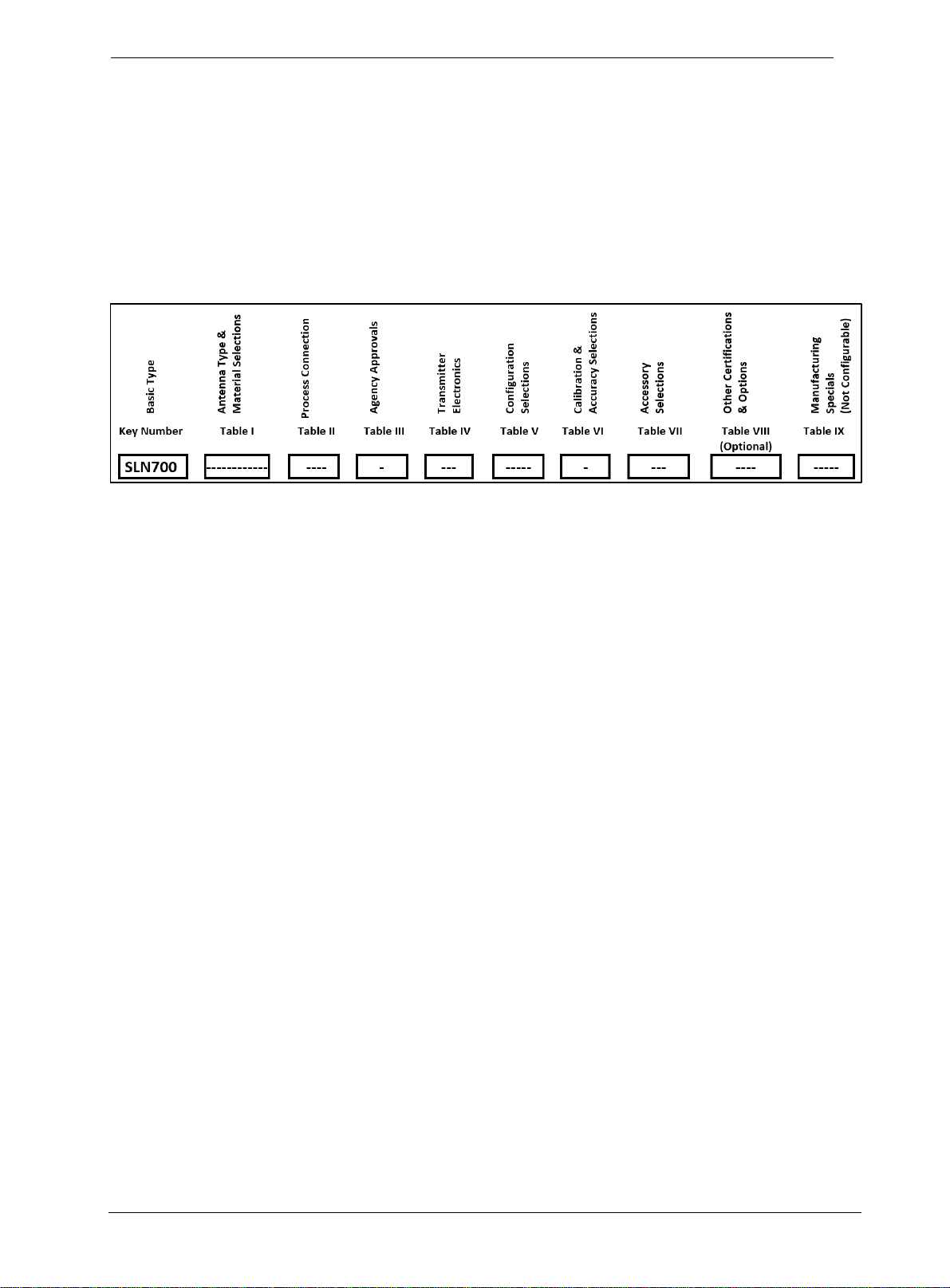
1.6 Transmitter Model Number Description
The model number is comprised from a number of selections and options that can be specified
when ordering the transmitter. It includes a basic transmitter type such as SLN720 (standard
temperature, standard pres s ure) followed by a maximum of nine additional character strings that
can be selected from a corresponding Table in the Model Selection Guide (MSG).
The basic model number structure is shown in Figure 1-3.
Figure 1-3: Standard SLN 700 Model Number
For a more complete description of the various configuration items and options, refer to the SLN
700 Product Specification (34-SL-03-06) and Model Selection Guide (34-SL-16-20).
1.7 Safety Certification Information
SLN transmitter models are available for use in Intrinsic Safe locations, including IECEx,
ATEX, and NEPSI approvals. See SLN 700 Product Specification (34-SL-03-06) or SLN 700
Quick Start Guide (34-SL-25-14) for details and other approvals.
Page 4 SLN 700 SmartLine NCR Level Transmitter User’s Manual Revision 1

2 Radar Level Measurement
2.1 Overview
This chapter describes the theory of operation of the transmitter and discusses how
measurements are affected by tank and process conditions.
2.2 Theory of Operation
The fundamental principle of operation is level measurement through the reflection of frequency
modulated radar waves (FMCW technique). The antenna emits a continuous wave of radiation
near 80 GHz whose frequency linearly increases in time in a saw tooth pattern. When the return
pulse is detected by the same antenna, the processing electronics use a Fourier Transform
technique to calculate the difference between the frequency of the generated and reflected signal.
This difference is proportional to the distance of reflection.
Revision 1 SLN 700 SmartLine NCR Level Transmitter User’s Manual Page 5
3 Mounting
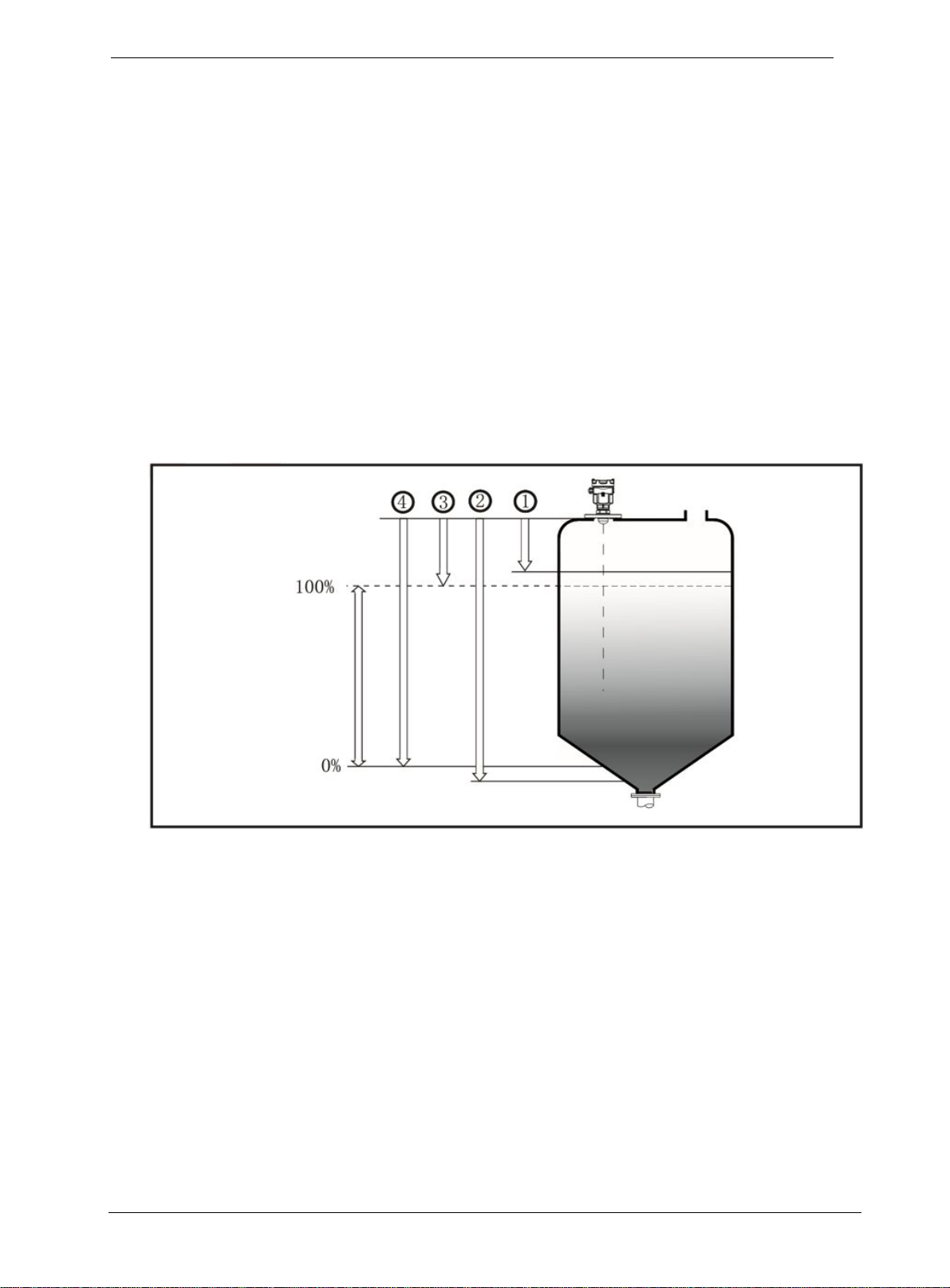
Due to the finite beam angle and resulting transmission cone, there should be no obstacles in the area
radiated by the transmitted microwave beam from the lower edge of the antenna to the material su rf ace to
be measured. Therefore, it is necessary to avoid these facilities in the tank during installation. These
include ladders, limit switches, heating equipment, supports, etc. If necessary, some of the obstacles can
be removed from the measurement using background subtraction ("Virtual Echo Learning"). In addition,
please note that the microwave beam should not intersect with tank fluid in or out flows. Please also note
that the highest material level should not enter the near range (see Figure 3-1), the instrument should be
kept at a certain distance from the wall of tank wall and the transmitting antenna should be perpendicular
to the measured material surface as much as possible. The instruments installed in a hazardous classified
area shall follow the local national installation regulations.
The reference plane for measurement is the sealing surface of threads or flang es.
1. Near distance
2. Far distance
3. Distance at which sensor reads 100 % level (or current)
4. Distance at which sensor reads 0 % level (or current)
Figure 3-1: Graphical illustration
Page 6 SLN 700 SmartLine NCR Level Transmitter User’s Manual Revision 1
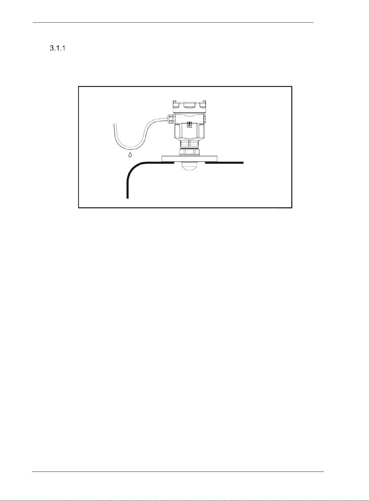
Moisture-proof
For instruments that are installed outside, in a wet environment, and cooling or heating tanks, the
cable gland must be tightened. The cable, at the cable gland entry, must be bent downward to
prevent moisture as shown in Figure 3-2.
Figure 3-2: Moisture-proof diagram
Revision 1 SLN 700 SmartLine NCR Level Transmitter User’s Manual Page 7
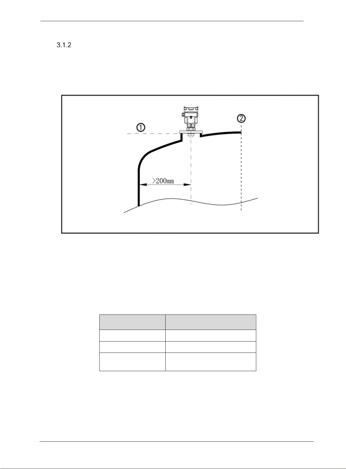
Installation position
During the installation, please note that the instrument should be kept minimal distance to tank
wall from the vessel wall. For different antenna, please refer to Table 3-1.
However, the instrument must not under any circumstances be mounted closer than 200mm to
the vessel wall or values calculated from Table 3-1.
1. Reference plane
2. Center of the vessel or symmetry axis
Figure 3-3: Installation position, >200 mm
Table 3-1: Minimal distance to tank wall
SLN700 Model Min distance to tank wall
83A 1/5 × Tank Height
82A 82B 83B 83C 1/10 × Tank Height
82C 82D 83D 83E
87A 87B 87C 87D
1/20 × Tank Height
Page 8 SLN 700 SmartLine NCR Level Transmitter User’s Manual Revision 1
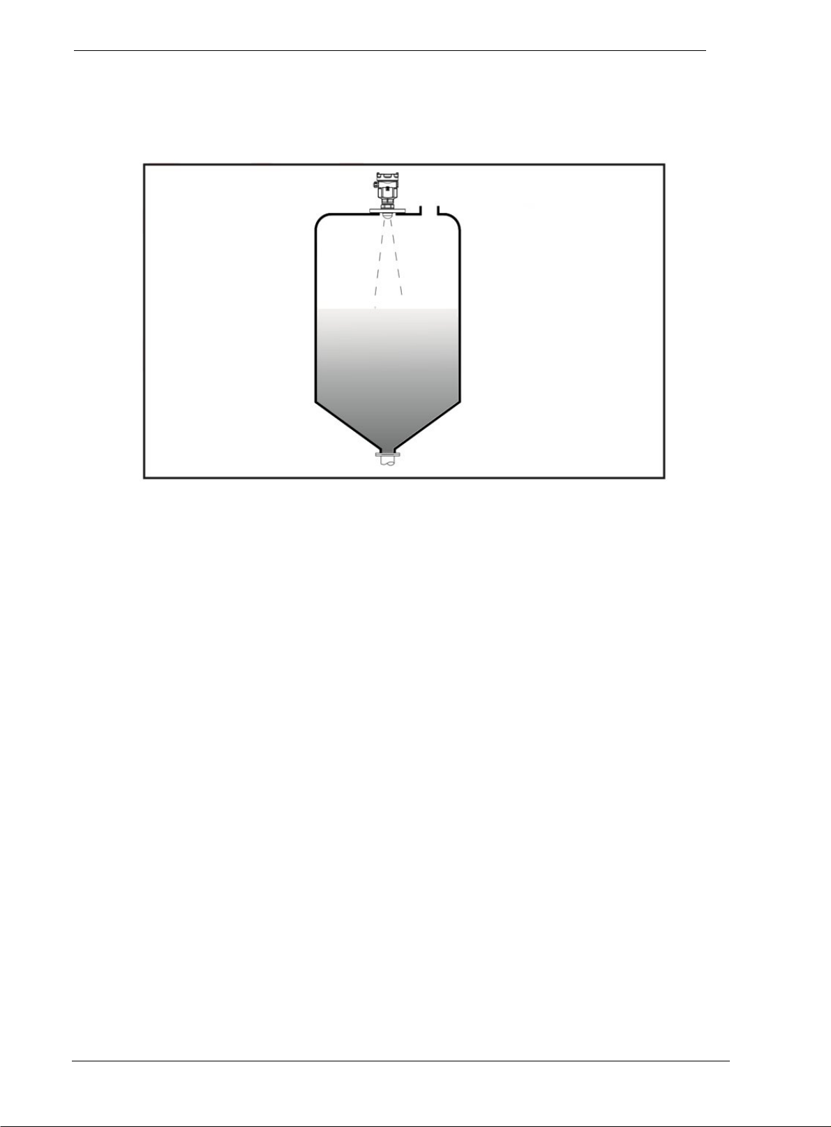
For the conical vessel with a flat tank top, the best installation position of instrument is the top
center of the vessel, which ensures that the bottom of the container is measured.
Figure 3-4: Conical vessel installation
Revision 1 SLN 700 SmartLine NCR Level Transmitter User’s Manual Page 9
 Loading...