

Honeywell SLN 700 Installation Guide
SLN 700 Quick Start I nst allation Guide
34-SL-25-14, Revision 2, November 2020
Revision History
2.0 – November 2020
°C °F °C °F
Ambient
-25 to 80
-13 to 176
-40 to 80
-40 to 176
Humidity %RH
0 to 100
0 to 100
Series
Medium
Applications
Process
connections
82 Series
Liquid
Strong
Flange options
83 Series
Liquid
Strong
Thread
87 Series
Solid
Storage
Flange
SmartLine Level Non-Contact Radar
This document provides descriptions and
procedures for the quick installation of
Honeywell’s SmartLine Non-Contact Radar
Level Transmitters.
The SmartLine Level Non-Contact Radar is
available as a family of SLN72x models for
liquid and solid applications.
Copyrights, Notices and Trademarks
Copyright 2020 by Honeywell
Revision 1.0, July 2020
Documentation
To access complete documentation, including language variants, scan
the QR code below using your smart phone/device or QR code scanner.
Go to the APP store for your free Smartphone QR scanner
Or you can follow the URL to access the online SmartLine HUB page.
The HUB page will contain direct links to open SmartLine product
documentation.
URL QR Code
https://hwll.co/SmartLineHUB
INTRODUCTION
The Smartline SLN700L is available for both liquid and solid non-contact rada r level
measurement. Each model is available with a range of flange or threaded antenna,
lens diameters, process connection, and accessories to suit most applications.
Mounting the Transmitter
INSTALLATION
Evaluate the site selected for the SmartLine SLN700 installation with respect to the
process system design specifications in table 1. Please note that the display can
become unreadable below -20C (-4
increases.
Operating conditions
°F)
Parameter
Temperature
Table 1: Operating Conditions
Operative Limits
1
Trademarks
SFC, SmartLine, ST 800 and ST 700
are U.S. registered trademarks of
Honeywell Inc.
HART® and FOUNDATION™ are
trademarks of the FieldComm
Group™
but it will recover once the temperature
Transportation and
Storage
Table of Contents
INTRODUCTION ........................................................................................................ 1
INSTALLATION .......................................................................................................... 1
MOUNTING THE TRANSMITTER .............................................................................. 2
Installation position ..................................................................................................... 2
Conduit Entry Plugs and Adaptors .............................................................................. 3
WIRING ...................................................................................................................... 3
Hazardous Locations & Intrinsic Safety .................................................................... 4
EU Declaration of Conformity .................................................................................... 4
The full text of the EU declaration of conformity is available at the following internet
address:
https://www.honeywellprocess.com/library/support/Public/Documents/50164363.pdf 4
The SLN700 transmitters comply with the following directives ................................... 4
EMC Conformity ......................................................................................................... 4
The SLN700 transmitters comply with the following EMC standards .......................... 4
Table 1: Operating Conditions .................................................................................... 1
Table 2: Process Connectors ...................................................................................... 1
Table 3: Minimal distance to tank wall ........................................................................ 2
Table 4: Nozzle specification table.............................................................................. 2
Table 5: Maximum Loop Resistance (Ω) ..................................................................... 3
Table 6: Hazardous Location Ratings ......................................................................... 4
Table 7: Intrinsic Safety Entity Parameters ................................................................. 4
Table 8: Process Temperature Vs Temperature Class ............................................... 4
Table 9: Display Menu Tree Basic Settings, Display and Diagnostics ........................ 4
Figure 1: Graphical illustration .................................................................................... 2
Figure 2: Installation position, >200 mm ..................................................................... 2
Figure 3: Conical vessel installation ............................................................................ 2
Figure 4: Nozzle specifications diagram ..................................................................... 2
Figure 5: Agitation ....................................................................................................... 3
Figure 6: Electronic Housing Conduit Entries .............................................................. 3
Figure 7: Maximum Loop Resistance (Ω).................................................................... 3
Figure 8: 2-wire wiring for HART ................................................................................. 3
Process Connector
The 80 GHz non-contact radar transmitter has three different series of products and
associated process connections.
For list of all options and accessories please refer to the product specifications,
which is available, here: https://www.honeywellprocess.com/smartline-level-
transmitter.aspx.
Table 2: Process Connectors
Tables
Figures
corrosive liquid
vapors or
foam
corrosive or
pressure
resistant
liquid
vessel/proces
s vessel or
high dust
applications
options
options
SLN700 Quick Start Installation Guide 1
82C 82D 83D 83E
87A 87B 87C 87D
Nozzle
d(mm)
Maximum Nozzle Height h(mm)
82A 82B
83B 83C
82C 82D
83D 83E
87A 87B
87C 87D
40
150
NA
NA
NA
50
150
150
NA
NA
80
200
200
200
NA
100
300
300
300
300
125
400
400
400
400
150
500
500
500
500
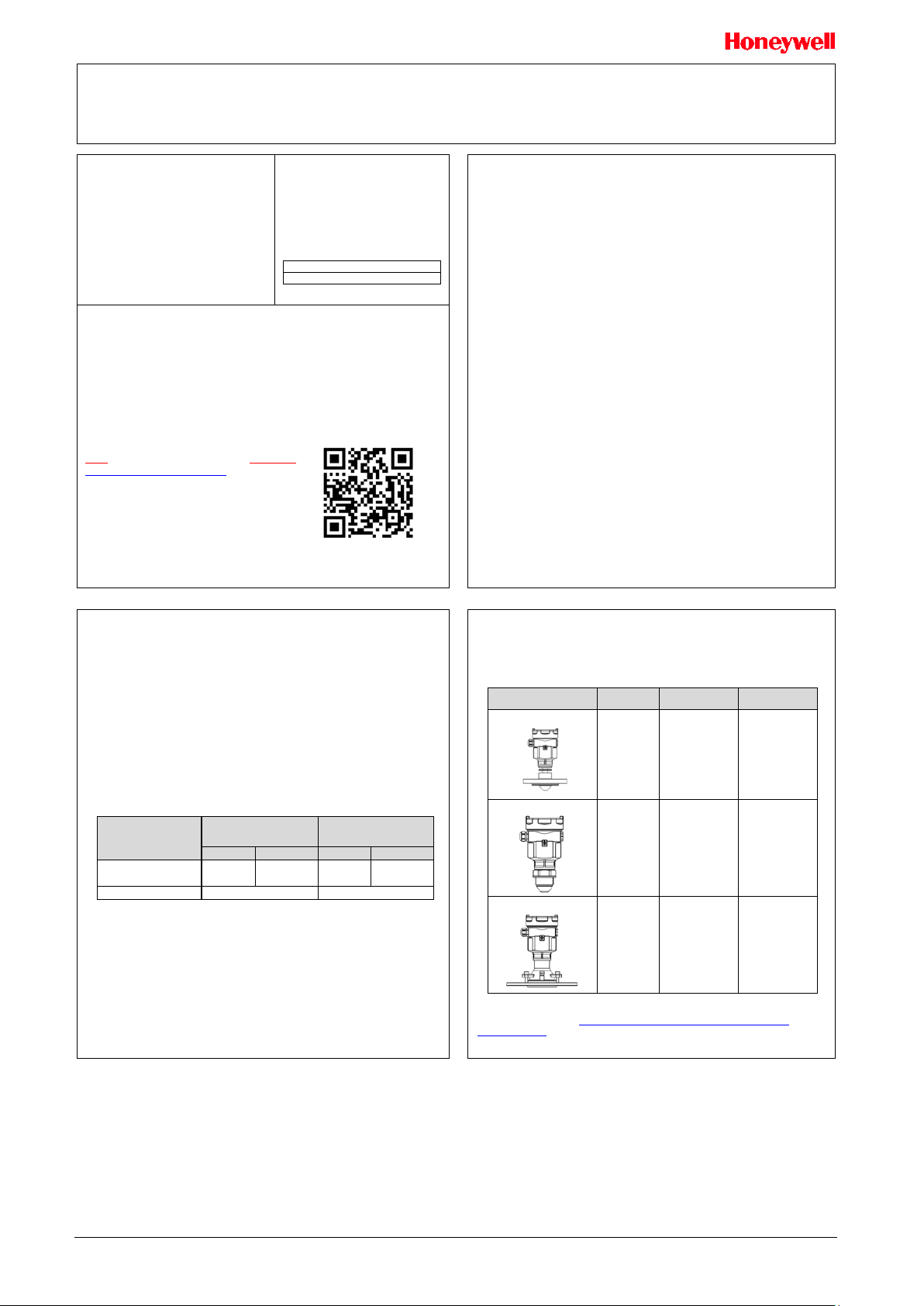
MOUNTING THE TRANSMITTER
There should be no obstacles in the area radiated by the transmitted microwave
beam from the lower edge of the antenna to the material surface to be measured
within the cone angle of the radar beam. These obstacles include ladders, limit
switches, heating equipment, supports, etc. When these are unavoidable, the gauge
offers background subtraction (“Virtual Echo Learning”) so that obstacles will be
ignored during level measurement. In addition, please note that the microwave beam
should not intersect with tank fluid in or out flows. In addition, the highest liquid or
solid tank level should not encroach into the upper blocking distance of the gauge
(typically a few cm). (see Figure 1), The instrument should be kept at a certain
distance from the tank wall and the transmitting antenna should be perpendicular to
the measured material surface as much as possible.
The instruments installed in a hazardous classified area shall follow the local national
installation regulations.
The reference plane for measurement is the sealing surface of threads or flanges.
1. Near (blocking) distance
2. Far distance
3. Distance at which sensor reads 100% level (or current)
4. Distance at which sensor reads 0 % level (or current)
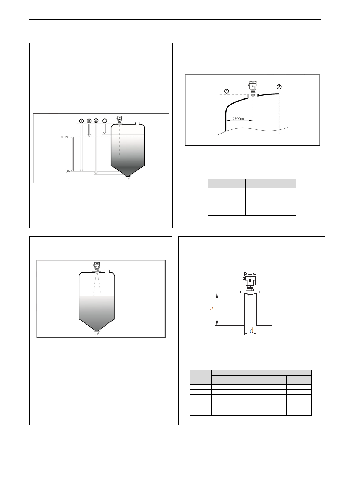
For a conical vessel with a flat tank top, the best installation position of the instrument
is the top center of the vessel, which ensures that the bottom of the container is
measured.
Figure 1: Graphical illustration
Figure 3: Conical vessel installation
Installation position
The minimum distance between the antenna and tank wall is variable for different
antenna. Please refer to Table 3.to calculate the minimum distance for your particular
model. In no instance, should the instrument be mounted closer than 200 mm to the
tank wall.
1. Reference plane
2. Center of the vessel or symmetry axis
Nozzle installations
In the case of a tank fluid or solid with good reflection properties (high dielectric
constant), the sensor may be mounted on a nozzle. The background subtraction ("virtual
echo learning") feature can further reduce false echoes from nozzle openings.
Table 4 shows detail of the size limitations of the nozzle.
Diameter
Figure 2: Installation position, >200 mm
Table 3: Minimal distanc e to tank wall
SLN700 Model Min distance to tank wall
83A 1/5 × Tank Height
82A 82B 83B 83C 1/10 × Tank Height
Figure 4: Nozzle specifications diagram
Table 4: Nozzle specification table
83A
1/20 × Tank Height
SLN700 Quick Start Installation Guide 2
 Loading...