

Page 1

SLG 700
SmartLine Level Transmitter
Guided Wave Radar
User’s Manual
34-SL-25-11
Revision 9.0
July 2020
Honeywell Process Solutions
Page 2

Copyrights, Notices and Trademarks
© Copyright 2020 by Honeywell International
Revision 9.0, July 2020
While the information in this document is presented in good faith and believed to be
accurate, Honeywell disclaims any implied warranties of merchantability and fitness for a
particular purpose and makes no express warranties except as may be stated in the written
agreement with and for its customers. In no event is Honeywell liable to anyone for any
indirect, special, or consequential damages. The information and specifications in this
document are subject to change without notice.
Honeywell, TDC3000, SFC, SmartLine, PlantScape, Experion PKS, and TotalPlant are
registered trademarks of Honeywell International Inc. Other brand or product names are
trademarks of their respective owners.
Honeywell Process Solutions
1250 W Sam Houston Pkwy S
Houston, TX 77042
Page ii SLG 700 SmartLine Level Transmitter User’s Manual Revision 9
Page 3

About This Manual
This manual is a detailed how to reference for installing, wiring, configuring, starting up,
operating, maintaining, calibrating, and servicing Honeywell’s family of SLG 700 SmartLine
Guided Wave Radar Level Transmitters. Users who have a Honeywell SLG 700 SmartLine
Guided Wave Radar Level Transmit ter con figu red fo r HA RT
SLG 700 Series HART
Option User’s Manual, Document #34-SL-25-06. Users who have a
Honeywell SLG 700 SmartLine Guided Wave Radar Level Transmitter configured for
Fieldbus operation are referred to the SLG 700 Series Foundation
Manual, Document #34-SL-25-07.
The configuration of your Transmitter depends on the mode of operation and the options
selected for it with respect to operating controls, displays and mechanical installation. This
manual provides detailed procedu res to ass ist first-time users, and it further includes
keystroke summaries, where appropriate, as quick reference or refreshers for experienced
personnel.
To digitally integrate a Transmitter with one of the following systems:
• For the Experion PKS, you will need to supplement the information in this document
with the data and procedures in the Experion Knowledge Builder.
• For Honeywell’s TotalPlant Solutions (TPS), you will need to supplement the
information in this document with the data in the PM/ A PM Sm artLine Tran smitter
Integration Manual, which is supplied with the TDC 3000 book set. (TPS is the evolution
of the TDC 3000).
protocol are referred to the
TM
Fieldbus Option User’s
Revision Histo r y
SLG 700 SmartLine Level Guided Wave Radar Transmitter User’s Manual,
Document #34-SL-25-11
Rev. 1.0 March 2015 First release
Rev. 2.0 April 2015 Updates to troubleshooting and Display menus
Rev. 3.0 June 2015 Security Considerations and Vulnerability added.
Rev. 4.0 June 2016 Updates for the R101 release. Including SLG726.
Rev. 5.0 July 2016 Display menus updated.
Rev. 6.0 December 2016 False Echo suppression, improved interface thickness
Rev. 7.0 February 2017 Troubleshooting section and Fieldbus updates
Rev. 8.0 December 2017 Saturated Steam application (R200)
Rev. 9.0 July 2020 approvals update (INMETRO)
Revision 9 SLG 700 SmartLine Level Transmitter User’s Manual Page iii
Page 4

References
The following list id entifies publ ica tions that may contain information rele v an t to th e in fo rmation
in this document.
SLG 700 SmartLine Guided Wave Radar Level Transmitter Quick Start Guide,
Document #34-SL-25-04
SLG 700 SmartLine Guided Wave Radar Level Transmitter Safety Manual,
Document #34-SL-25-05
SLG 700 SmartLine Guided Wave Radar Level Transmitter HART Option Manual,
Document #34-SL-25-06
SLG 700 SmartLine Level Transmitter Guided Wave Radar FOUNDATION Fieldbus Option
Manual, Document #34- SL-25-07
SLG 700 SmartLine Level Transmi tter Product Specification Document #34-SL-03-03
Patents
The Honeywell SLG 700 SmartLine Guided Wave Radar Level Transmitter family is covered by
U. S. Patents 9329072, 9329073, 9476753 and 9518856 and 9329074, 9574929, 9618612,
9711838 and their foreign equivalents and other patents pending.
Support and Contact Information
For Europe, Asia Pacific, North and South America contact details, refer to the back page of this
manual or the appropriate Honeywell Support web site:
Honeywell Corporate www.honeywell.com
Honeywell Process Solutions https://www.honeywellprocess.com/*
Honeywell SmartLine Level https://www.honeywellprocess.com/smartline-level-transmitter.aspx
Telephone and Email Contacts
Area Organization Phone Number
United States and
Canada
Global Email
Support
Honeywell Inc.
Honeywell Process
Solutions
1-800-343-0228 Customer Service
1-800-423-9883 Global Technical Support
hfs-tac-support@honeywell.com
Page iv SLG 700 SmartLine Level Transmitter User’s Manual Revision 9
Page 5
Symbols Descriptions and Definitions
The following symbols may appear in this document.
Symbol Definition
ATTENTION: Identifies information that requires special consideration.
TIP: Identifies advice or hints for the user, often in terms of performing a
CAUTION Indicates a situation which, if not avoided, may result in equipment or
task.
work (data) on the system being damaged or lost, or may result in the
inability to properly operate the process.
CAUTION: Indicates a potentially hazardous situation which, if not
avoided, may result in minor or moderate injury. It may also be used to
alert against unsafe practices .
CAUTION symbol on the equipment refers the user to the product manual
for additional information. The symbol appears next to required
information in the manual.
WARNING: Indicates a potentially hazardous situation, which, if not
avoided, could result in serious injury or death.
WARNING symbol on the equipment refers the user to the product
manual for additional information. The symbol appears next to required
information in the manual.
WARNING, Risk of electrical shock: Potential shock hazard where
HAZARDOUS LIVE voltages greater than 30 Vrms, 42.4 Vpeak, or 60
VDC may be accessible.
ESD HAZARD: Danger of an electro-static discharge to which equipment
may be sensitive. Observe precautions for handling electrostatic sensitive
devices.
Protective Earth (PE) terminal: Provided for connection of the protective
earth (green or green/yellow) supply system conductor.
Functional earth terminal: Used for non-safety purposes such as noise
immunity improvement. Note: This connection shall be bonded to
Protective Earth at the source of supply in accordance with national local
electrical code requirements.
Earth Ground: Functional earth connection. Note: This connection shall
be bonded to Protective Earth at the source of supply in accordance with
national and local electrical code requirements.
Chassis Ground: Identifies a connection to the chassis or frame of the
equipment shall be bonded to Protective Earth at the source of supply in
accordance with national and local electrical code requirements.
The Factory Mutual® Approval mark means the equipment has been
rigorously tested and certified to be reliable.
Revision 9 SLG 700 SmartLine Level Transmitter User’s Manual Page v
Page 6

Symbol Definition
The Canadian Standards mark means the equipment has been tested
and meets applicable standards for safety and/or performance.
The Ex mark means the equipment complies with the requirements of the
European standards that are harmonized with the 2014/68/EU Directive
(ATEX Directive, named after the French "ATmosphere EXplosible").
Page vi SLG 700 SmartLine Level Transmitter User’s Manual Revision 9
Page 7

Contents
1 Introduction .......................................................................................................... 1
1.1 Overview ................................................................................................................................. 1
1.2 Transmitter Models ................................................................................................................. 1
1.3 Transmitter Components ........................................................................................................ 1
1.3.1 Overview of components .................................................................................................... 1
1.3.2 Electronics Housing ............................................................................................................ 2
1.3.3 Sensor Housing .................................................................................................................. 3
1.3.4 Process Connector ............................................................................................................. 3
1.3.5 Probe .................................................................................................................................. 4
1.4 Communicating with the Transmitter ...................................................................................... 6
1.4.1 4-20 mA HART .................................................................................................................. 6
1.4.2 FOUNDATIONTM Fieldbus (FF) .......................................................................................... 8
1.4.3 DTM-based tools and Experion .......................................................................................... 9
1.5 SLG 700 Transmitter nameplate .......................................................................................... 11
1.6 Transmitter Model Number Description ................................................................................ 13
1.7 Safety Certification Information ............................................................................................ 13
1.7.1 Safety Integrity Level (SIL) ............................................................................................... 13
1.8 Security Considerations ........................................................................................................ 14
1.9 Measurement Options Licensing .......................................................................................... 14
2 Radar Level Measurement ................................................................................. 15
2.1 Overview ............................................................................................................................... 15
2.2 Theory of Operation .............................................................................................................. 15
2.2.1 TDR for Interface and Flooded Measurements ................................................................ 17
2.3 Signal processing configuration ............................................................................................ 18
2.3.1 Amplitude Tracking ........................................................................................................... 19
2.3.2 Full-tank Detection ............................................................................................................ 19
2.3.3 Maximum Fill Rates, Latching and Timeouts.................................................................... 20
2.4 Signal Interferences and background echoes ...................................................................... 21
2.4.1 Field and Obstacle background ........................................................................................ 21
2.4.2 Static and Dynamic backgrounds ..................................................................................... 21
2.4.3 Accuracy and measurement range specifications ............................................................ 22
2.5 Process Applications ............................................................................................................ 28
2.5.1 Single Liquid ..................................................................................................................... 28
2.5.2 Two Liquid Applications .................................................................................................... 28
2.5.3 Low Dielectric Applications ............................................................................................... 30
2.5.4 Steam Boiler Applications ................................................................................................. 31
2.6 Process Condition Considerations ....................................................................................... 32
2.6.1 Turbulence ........................................................................................................................ 32
2.6.2 Foam or Emulsions ........................................................................................................... 32
2.6.3 FEP Pr ob e ........................................................................................................................ 32
Revision 9 SLG 700 SmartLine Level Transmitter User’s Manual Page vii
Page 8

2.7 Container Considerations ...................................................................................................... 33
2.7.1 Shapes .............................................................................................................................. 33
2.7.2 Materials (plastic vs. metal) ............................................................................................... 33
2.8 Blocking distance high and blocking distance low guidance ................................................ 34
2.8.1 Blocking distance high (BDH) guidance ............................................................................ 34
2.8.2 Blocking distance low (BDL) guidance .............................................................................. 34
2.8.3 Blocking Distance, Full Tank Detection and Latching modes ........................................... 34
3 Transmitter Installation ....................................................................................... 36
3.1 Preparation ............................................................................................................................ 36
3.1.1 Installation sequence ........................................................................................................ 36
3.1.2 Tools .................................................................................................................................. 37
3.2 Mechanical Installation .......................................................................................................... 38
3.2.1 Check for correct probe dimensions and strength ............................................................ 38
3.2.2 Accuracy and measuring range specifications .................................................................. 38
3.2.3 Trim the probe length ........................................................................................................ 47
3.2.4 Attach/assemble the probe ............................................................................................... 48
3.2.5 Centering Disks and configured probe length ................................................................... 61
3.2.6 Mounting the transmitter ................................................................................................... 67
3.2.7 Suitable mounting position ................................................................................................ 73
3.2.8 Optimum Operating Temperature ..................................................................................... 74
3.2.9 Temperature requirements ................................................................................................ 75
3.2.10 Mounting on a non-metallic container ........................................................................... 83
3.2.11 Rotate transmitter housing ............................................................................................ 86
3.2.12 Secure the probe ........................................................................................................... 86
3.2.13 Install conduit entry plugs and adapters ....................................................................... 89
3.2.14 Flange pressure ratings ................................................................................................ 90
3.2.15 Material Exposed to Tank Atmosphere ......................................................................... 90
3.3 Electrical Installation ............................................................................................................. 91
3.3.1 Wiring a transmitter ........................................................................................................... 91
3.3.2 HART / 4-20mA Voltage Operating Ranges ..................................................................... 91
3.3.3 Terminal Connections ....................................................................................................... 93
3.3.4 FOUNDATION Fieldbus .................................................................................................... 94
3.3.5 Wiring Procedure............................................................................................................... 94
3.3.6 Lightn ing Prot ec tio n .......................................................................................................... 95
3.3.7 Supply Voltage Limiting Requirements ............................................................................. 95
3.3.8 Process Sealing ................................................................................................................ 95
3.3.9 Explosion-Proof Conduit Seal ........................................................................................... 95
4 Operating the Transmit ter .................................................................................. 96
4.1 User interface options ........................................................................................................... 96
4.1.1 Transmitter advanced displays with buttons ..................................................................... 96
4.1.2 DTM or DD – HART and FF .............................................................................................. 96
4.2 Three-Button Operation ........................................................................................................ 97
4.2.1 Three-button operation without displ a y ............................................................................. 97
4.2.2 Menu Navigation ............................................................................................................... 99
4.2.3 Data Entry ......................................................................................................................... 99
4.2.4 Editing a Numeric Value .................................................................................................. 100
4.2.5 Selecting a new setting from a list of choices ................................................................. 100
Page viii SLG 700 SmartLine Level Transmitter User’s Manual Revision 9
Page 9

4.3 The Advanced Display Menu .............................................................................................. 101
4.3.1 Correlation Model Recalculation ..................................................................................... 102
4.4 Monitoring the Advanced Display ....................................................................................... 120
4.4.1 Advanced Displays ......................................................................................................... 120
4.4.2 Button operation during monitoring ................................................................................ 122
4.5 Changing the Failsafe Direction and Write Protect Jumpers (Including Simulation mode) 123
4.5.1 Procedure to Establish Failsafe Operation ..................................................................... 123
5 Maintenance .................................................................................................... 126
5.1 Overview ............................................................................................................................. 126
5.2 Preventive Maintenance Practices and Schedules ............................................................ 126
5.3 Procedures ......................................................................................................................... 129
5.3.1 Output Check Procedures .............................................................................................. 129
5.3.2 Constant Current Source Mode Procedure .................................................................... 130
5.3.3 Replacing the Terminal Block ......................................................................................... 131
5.3.4 Replacing the Display Assembly .................................................................................... 131
5.3.5 Replacing the Communication Module ........................................................................... 131
5.4 How to replace the Sensor Housing ................................................................................... 132
5.4.1 Tools required. ................................................................................................................ 134
5.4.2 Hazar dous Loc at ions ...................................................................................................... 140
5.4.3 Appendix: Reconciling Model Numbers .......................................................................... 140
5.5 Replacing the Wire Probe ................................................................................................... 142
5.5.1 Tools required ................................................................................................................. 142
5.5.2 Procedures ..................................................................................................................... 143
5.6 Trimming Coaxial Probes ................................................................................................... 147
5.6.1 Tools required ................................................................................................................. 147
5.6.2 Procedure ....................................................................................................................... 147
5.7 Saturated Steam Probe Installation .................................................................................... 150
5.7.1 Tools required ................................................................................................................. 150
5.7.2 Procedure ....................................................................................................................... 150
6 Troubleshooting ............................................................................................... 154
6.1 Error Messages .................................................................................................................. 154
6.1.1 Diagnostics ..................................................................................................................... 154
6.2 Diagnosing SLG720 Coaxial Probe misassembly .............................................................. 157
7 Parts List .......................................................................................................... 161
7.1 Overview ............................................................................................................................. 161
8 Glossary ........................................................................................................... 162
Revision 9 SLG 700 SmartLine Level Transmitter User’s Manual Page ix
Page 10

9 Appendix Certifications ..................................................................................... 165
9.1 Safety Instrumented Systems (SIS) Installations ................................................................ 165
9.2 European Directive Information (EU) .................................................................................. 165
9.3 Hazardous Locations Certifications .................................................................................... 166
9.4 Marking ATEX Directive ...................................................................................................... 171
9.5 Conditions of Use for Ex Equipment, “Hazardous Location Equipment” or "Schedule of
Limitations" ...................................................................................................................................... 172
9.6 Control Drawing................................................................................................................... 174
9.7 China RoHS ........................................................................................................................ 178
10 Security ............................................................................................................ 179
10.1 How to report a security vulnerability .................................................................................. 179
Page x SLG 700 SmartLine Level Transmitter User’s Manual Revision 9
Page 11

List of Figures
Figure 2-1: Components of the Level transmitter ................................................................................... 2
Figure 2-2: Example of HART connection RL ........................................................................................ 7
Figure 2-3: Example of FF connection ................................................................................................... 8
Figure 2-4: Example of a FF network ................................................................................................... 11
Figure 2-5: Transmitter nameplate example ........................................................................................ 12
Figure 2-6: Standard SLG 700 Model Num ber ..................................................................................... 13
Figure 2-7: Safety certification example ............................................................................................... 13
Figure 2-1: GWR measurement ........................................................................................................... 16
Figure 2-2: Sample Echo Curve ........................................................................................................... 17
Figure 2-3: Interface measurement ...................................................................................................... 18
Figure 2-4 Radar Impulse Reflection model ......................................................................................... 19
Figure 2-5: Upper transition zone length and minimum blocking distance high (BDH) and minimum
blocking distance low (BDL) for coax probes in water.......................................................................... 23
Figure 2-6: Upper transition zone length and minimum blocking distance high (BDH) and minimum
blocking distance low (BDL) for coax probes in oil. .............................................................................. 23
Figure 2-7: Transition zone lengths and minimum blocking distance high (BDH) for single lead probes
in water. ................................................................................................................................................ 24
Figure 2-8: Transition zone lengths and minimum blocking distance high (BDH) for single lead (i.e.
rod and rope) probes in oil. ................................................................................................................... 25
Figure 2-9 Minimum blocking distances, steam application for a threaded HTHP process connector 25
Figure 2-10 Minimum blocking distance, steam application for a flanged HTHP process connector .. 26
Figure 2-11: Two-liquids Flooded ......................................................................................................... 28
Figure 2-12: Two-liquids non-flooded. .................................................................................................. 29
Figure 2-13 Typical Echo steam application echo with vapor reference rod........................................ 31
Figure 2-14: Top vertical and angled mounting .................................................................................... 33
Figure 3-1 SLG720 probe dimensions, mm [in] .................................................................................... 40
Figure 3-2: SLG720 FEP probe dimensions, mm [in] ........................................................................... 41
Figure 3-3: SLG726 Threaded process connection probe dimensions; mm [in] .................................. 42
Figure 3-4 SLG726 Flanged process connection probe dimensions; mm [in] ..................................... 43
Figure 3-5: SLG726 Saturated steam application threaded process connection probe dimensions; mm
[in] ......................................................................................................................................................... 44
Figure 3-6: SLG726 Saturated steam application flanged process connection probe dimensions; mm
[in] ......................................................................................................................................................... 44
Figure 3-7: Example bending torque values ......................................................................................... 47
Figure 3-8: Drill 6-mm diameter hole at the position shown on the coaxial outer conductor. .............. 48
Figure 3-9: Rod probe assem bl y .......................................................................................................... 49
Figure 3-10: SLG726 flanged process connection, probe nut installation position, mm [in] ................ 50
Figure 3-11: Wire probe assembly ....................................................................................................... 51
Figure 3-12: SLG720 Coaxial probe assembly (single outer tube depicted) ....................................... 54
Figure 3-13: SLG720 Coaxial probe assembly (single outer tube depicted) ....................................... 54
Figure 3-14: SLG726 Coaxial pro be ass embly .................................................................................... 59
Revision 9 SLG 700 SmartLine Level Transmitter User’s Manual Page xi
Page 12

Figure 3-15 Saturated steam application rod probe assembly ............................................................ 60
Figure 3-16: Saturated steam application coaxial probe assembly ..................................................... 60
Figure 3-17: Recommended location of holes for rod probes .............................................................. 63
Figure 3-18: Centering disks for wire and rod probes. ......................................................................... 64
Figure 3-19: Centering disks for FEP coated wire and rod probes ...................................................... 64
Figure 3-20: Probe length definition for rod probes using a centering disk ......................................... 67
Figure 3-21: Flanged SLG720 Transmitter, mm [in] ............................................................................ 67
Figure 3-22: Threaded (NPT ¾", 1", 1½", 2") SLG720 Transmitter, mm [in] ....................................... 68
Figure 3-23: Threaded (BSP/G ¾”, 1”, 1½”) SLG720 Transmitter, mm [in] ......................................... 69
Figure 3-24: Flanged SLG726 transmitter, mm [in] ............................................................................. 70
Figure 3-25: Threaded (NPT 1½", 2”) SLG726 transmitter, mm [in] .................................................... 71
Figure 3-26: Threaded (BSP/G 1½") SLG726 transmitter, mm [in] ..................................................... 72
Figure 3-27: Mounting posit ion ............................................................................................................ 73
Figure 3-28: SLG720 temperatur e limits .............................................................................................. 75
Figure 3-29: SLG726 temperatur e limits .............................................................................................. 76
Figure 3-30: SLG726 Maximum pressure based on maximum operating temperature ....................... 76
Figure 3-31: Flanged tank connection ................................................................................................. 78
Figure 3-32: Flange mounting .............................................................................................................. 79
Figure 3-33: Oversized nozzle configuration ....................................................................................... 80
Figure 3-34: Threaded tank connection ............................................................................................... 81
Figure 3-35: Tank roof mounting using threaded connection .............................................................. 81
Figure 3-36: Bypass installation ........................................................................................................... 82
Figure 3-37: Mounting on a non-metallic vessel .................................................................................. 83
Figure 3-38: Mounting in concrete silos ............................................................................................... 84
Figure 3-39: Remote mount ................................................................................................................. 85
Figure 3-40: Rotate transmitter housing .............................................................................................. 86
Figure 3-41: Anchoring wire probes ..................................................................................................... 87
Figure 3-42: Wire probe slack .............................................................................................................. 87
Figure 3-43: Anchoring coaxial probes ................................................................................................ 88
Figure 3-44: Transmitter operating ranges .......................................................................................... 91
Figure 3-45: HART 3-Screw Terminal Board and Grounding Screw ................................................... 93
Figure 4-1: Three-Button Option .......................................................................................................... 98
Figure 4-2: Advanced Display Formats with the Process Variable .................................................... 120
Figure 4-3: Locating the Failsafe and Write Protect Jumpers ............................................................ 124
Figure 5-1: Current Loop Test Connections....................................................................................... 130
Figure 5-2: Electronic Housing Components ..................................................................................... 131
Figure 5-3: Sensor Housing ............................................................................................................... 132
Figure 5-45-5: Part Number and Date Code (D/C) label on bottom of Terminal PCBA assembly .... 134
Figure 5-6: Location of sensor housing and attachment set screws.................................................. 135
Figure 5-7: Communications Housing Assembly ............................................................................... 136
Page xii SLG 700 SmartLine Level Transmitter User’s Manual Revision 9
Page 13

Figure 5-8: Rook Assembly ................................................................................................................ 137
Figure 5-9: - Sensor ribbon cable ...................................................................................................... 138
Figure 5-10: Location of RF-connector at bottom of sensor housing ................................................. 139
Figure 5-11- Model Number Mismatch Critical Error .......................................................................... 141
Figure 5-12 - Reconcile Model Numbers feature ............................................................................... 141
Figure 5-13 - No Trimming Zones on Outer Tube and Inner Rod ...................................................... 148
Figure 5-14 - Drill Hole Position on Outer Tube ................................................................................. 149
Figure 5-15 - Spacer and Locking Pin Installation .............................................................................. 149
Figure 5-16 - SLG726 flanged process connection, probe nut installation position, mm [in] ............. 151
Figure 5-17 - Saturated steam application rod probe assembly ........................................................ 152
Figure 5-18 - Saturated steam application coaxial probe assembly .................................................. 153
Revision 9 SLG 700 SmartLine Level Transmitter User’s Manual Page xiii
Page 14

List of Tables
Table 2-1: Features and Options ........................................................................................................... 1
Table 2-2: Available SmartLine GWR display characteristics ................................................................ 3
Table 2-3: Probe Selection ..................................................................................................................... 4
Table 2-1: Blocking Distance High ....................................................................................................... 26
Table 3-1: Installation sequence .......................................................................................................... 36
Table 3-2: Mechanical insta lla tio n sequenc e ....................................................................................... 38
Table 3-3: Sensor Details – All Models ................................................................................................ 39
Table 3-4: Minimum blocking distances and transition zones for the various probe types. ................ 39
Table 3-5: Minimum blocking distances and Minimum distance to inlet or surface with DC corrected
level for the Saturated Steam Application. ........................................................................................... 39
Table 3-6: Maximum measurement range for each probe type versus dielectric constant. ................ 39
Table 3-7: Tensile load limits for flexible probe.................................................................................... 45
Table 3-8: Rigid (i.e. rod and coaxial) probe mounting angle limits ..................................................... 45
Table 3-9: Rod probe bending torque limits (all lengths) ..................................................................... 45
Table 3-10: Coaxial probe bending load limits (all lengths) ................................................................. 45
Table 3-11: Recommended probe diameter and material of construction ........................................... 61
Table 3-12: Centering disk determination from pipe size and schedule .............................................. 65
Table 3-13: Centering disk dimensions ................................................................................................ 65
Table 3-14: Probe length for different probe types .............................................................................. 66
Table 3-15: Minimum recommended distance to container wall and obstacles (mm) ......................... 73
Table 3-16: SLG726 Maximum pressure based on maximum operating temperature in tabular form 77
Table 3-17: SLG720: Recommended nozzle dimensions ................................................................... 79
Table 3-18: SLG720 bypass and stillwell recommended diameters .................................................... 82
Table 3-19: SLG726 bypass and stillwell recommended diameters .................................................... 83
Table 3-20: Conduit entry plug installation ........................................................................................... 89
Table 3-21: Conduit adapter installation .............................................................................................. 89
Table 4-1: Three-Button Option Functions ........................................................................................... 99
Table 4-2: Three-Button Data Entry ................................................................................................... 100
Table 4-3: Advanced Display Main Menu Structure .......................................................................... 101
Table 4-4: Correlation Model Recalculation ....................................................................................... 102
Table 4-5: Display Config sub-menu .................................................................................................. 103
Table 4-6: Basic Configuration sub-menu .......................................................................................... 105
Table 4-7: Advanced Config sub-menu ............................................................................................. 109
Table 4-8: Monitor sub-menu ............................................................................................................. 114
Page xiv SLG 700 SmartLine Level Transmitter User’s Manual Revision 9
Page 15

Table 4-9: Advanced Displays with PV Format Display Indications ................................................... 121
Table 4-10: HART Failsafe and Write Protect Jumpers ..................................................................... 125
Table 4-11: FOUNDATION Fieldbus Simulation and W rite Protec t Jumpers .................................... 125
Table 5-1: Probe length calculated from spare probe model number. ............................................... 145
Table 6-1: SLG 700 Standard Diagnostics Messages ....................................................................... 155
Table 7-1: Parts .................................................................................................................................. 161
Revision 9 SLG 700 SmartLine Level Transmitter User’s Manual Page xv
Page 16

This page has been intentionally left blank
Page xvi SLG 700 SmartLine Level Transmitter User’s Manual Revision 9
Page 17

Standard Temperature Liquid Level Measurement
(-40 to 200°C/-1 to 40 bar)
High Temperature / High Pressure Liquid Level Measurement
(-60 to 450°C /-1 to 400 bar)
1.1 Overview
The SLG 700 Guided Wave Radar SmartLine transmitter is an electronic instrument
designed to measure levels of liquid and solid materials. Guided Wave Radar (GWR)
transmitters use time domain reflectometry with radar pulses guided by a metal probe and
reflected off a product surface to determine levels in tanks. In comparison to other level
measurement technologies, GWR provides a highly-accurate, cost-effective, reliable
measurement over a wide range of process conditions.
1.2 Transmitter Models
The SmartLine Guided Wave Radar (GWR) transmitter is available as a family of
SLG72X models for liquid applications. The pressure and temperature application ranges
for each model are summarized in Table 2-1.
1 Introduction
Table 2-1: Features and Options
Range Model
Each model is available with a range of probes, wetted materials, and accessories to suit
most applications.
1.3 Transmitter Components
Overview of components
As shown in
Figure 2-1 the transmitter consists of:
• Electronics housing containing
o Display module (optional)
o Buttons module (optional)
o Communications module
o Electrical terminal block assembly
SLG720
SLG726
• Sensor housing
• Process connector
• Probe, also known as a waveguide
Revision 9 SLG 700 SmartLine Guided Wave Radar User’s Manual 1
Page 18
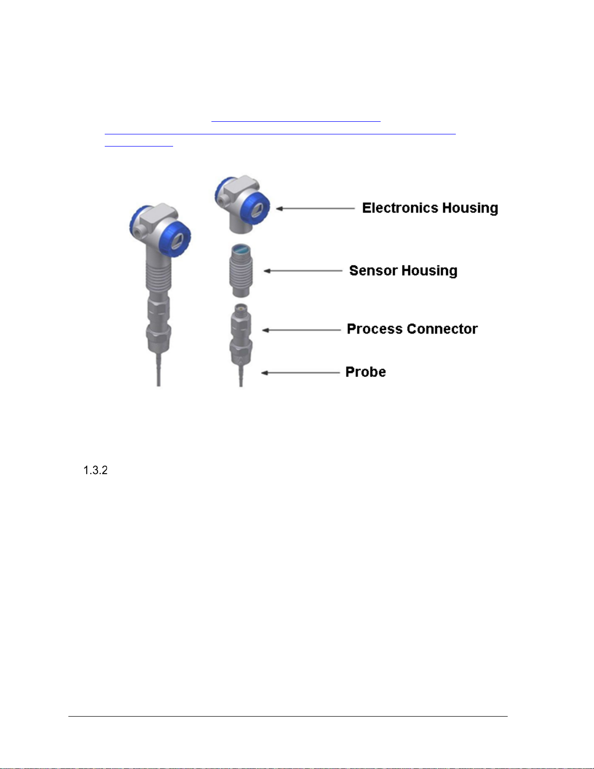
These components are described below.
Additional mounting and optional accessories are available, such as centering discs for
probes. For list of all options and accessories please re fer to the purchasing specifications,
which is available, here:
https://www.honeywellprocess.com/enUS/explore/products/instrumentation/process-level-sensors/Pages/smartline-leveltransmitter.aspx.
Figure 2-1: Components of the Level transmitter
Electronics Housing
The Electronics Housing contains these components. All components are replaceable in
the field.
Terminal Assembly: Provides connection points for the measurement signal and
power. Different terminal modules are required for HART
and FOUNDATION
TM
Fieldbus versions of the transmitters. Th e terminal is polarity insensitive. Lightning
protection is optional.
Communications module: The platform provides separate electronics modules for
HART
and FOUNDATIONTM Fieldbus versions of the transmitters. The
communication board for a certain communication protocol always requires terminal
assembly for the same type of communication. Descriptions of the communications
protocols are in the Glossary.
Optional Display: Table 2-2 lists features of the available display module.
Optional Buttons: Refer to Figure 4-1: Three-Button Option for more information.
Page 2 SLG 700 SmartLine Level Transmitter User’s Manual Revision 9
Page 19

Advanced
• 360° rotation in 90° increments
Supports transmitter messaging and maintenance mode indications
Table 2-2: Available Smar tL ine GW R displa y char a cterist i cs
Display
• Three configurable screen formats with configurable rotation timing
o Large process variable (PV)
o PV with bar graph
o PV with trend (1-999hrs, configurable)
• Echo stem plot for checking measurement accuracy
• Eight Screens with 3-30 sec. rotation timing and the use of 3-butto ns for
configuration.
• Standard and custom engineering units
• Diagnostic alerts and diagnostic messaging
• Multiple language support options:
o Option 1: EN, FR, GE, SP, RU, TU, IT
o Option 2: EN, CH, JP (Kanji)
• Supports 3-button configuration and calibration
•
To make changes to the transmitter setup or configuration without the use of an external
device such as a handheld or PC, an optional 3-Button Assembly is available. Use the
buttons and menus to:
• Configure transmitter
• Configure and navigate displays
Sensor Housing
The sensor housing contains the pulse generation and analysis hardware.
These electronics are potted to provide flame path resistance.
The sensor housing is available as a replaceable part.
Process Connector
Note:
Revision 9 SLG 700 SmartLine Level Transmitter User’s Manual Page 3
The process connector has the following functions.
• Separates the process environment from the external environment.
• Provides a threaded insert to the tank which removes the need for brackets to
mount the transmitter. Various mounting types are available, including popular
threads and flanges.
• Provides electrical feed-through to the probe.
Each of the SLG720 and SLG726 models have different process connector designs.
Each process connector design accepts a sub-set of the full range of probe types.
Page 20
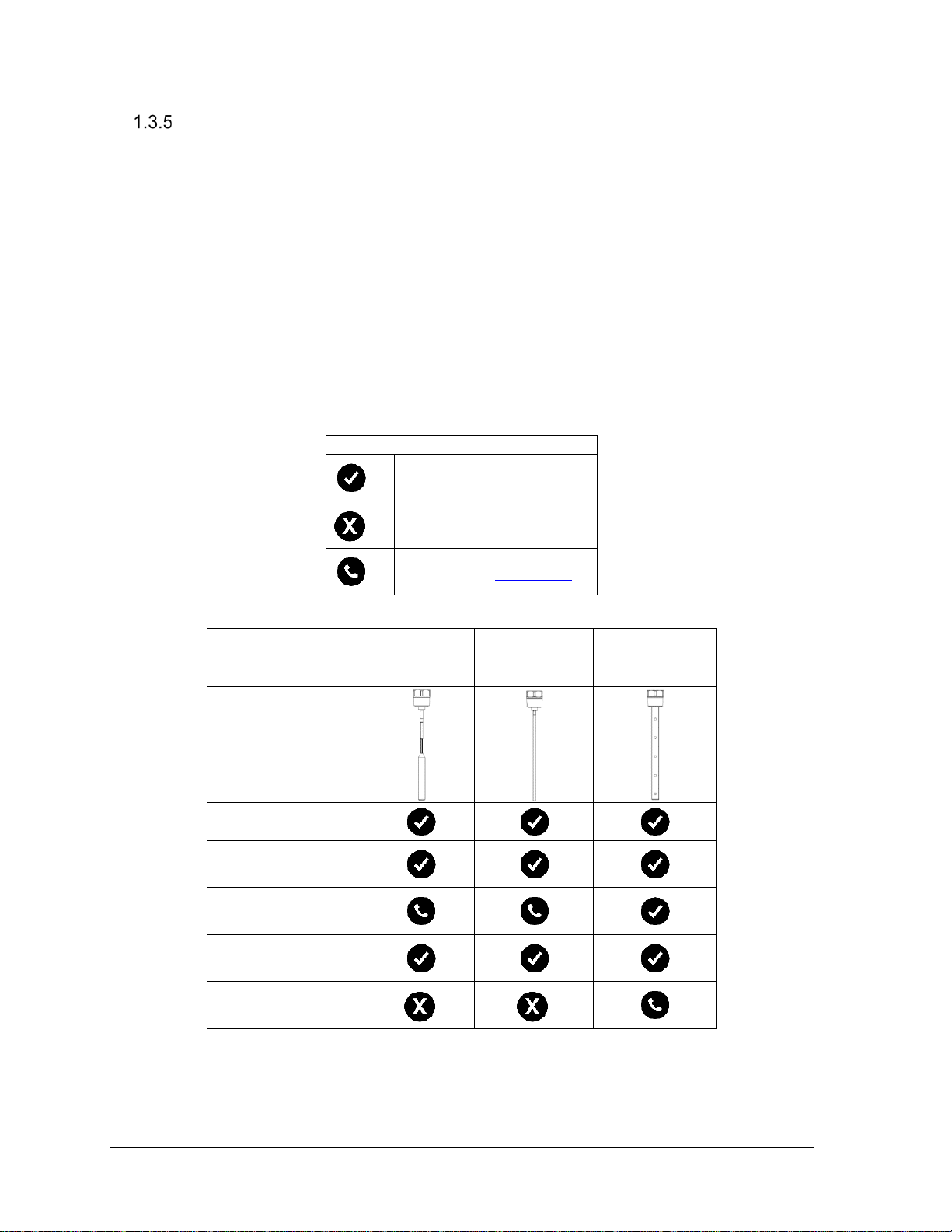
Legend
Level
Interface
Bubbling/boiling
Low-dielectric
Foam (liquid surface
Probe
The purpose of a Guided Wave Radar probe is to guide radar pulses produced by the radar
transmitter towards the material being measured. It also guides the reflected pulse back to the
transmitter for processing into a level measurement. The probe can be made of a single
conductor such as for single wire or rod probes, or two conductors for coaxial probes. For rigid
probes (rod and coaxial), multiple segments, each up to 2m long, can be connected.
The probe is also known in the industry as “waveguide”.
A single wire probe is the most common design; other designs are provided based on
application needs. For the purposes of this document the term “Wire” is being used, however
the term “Wire” and “Rope” are interchangeable.
Table 2-3 summarizes advantages and disadvantages of different probe constructions.
Installation details of each probe are described in Chapter 3.
Table 2-3: Probe Selection
Yes
No
Contact the TAC team
(liquid/liquid)
surfaces
constant liquids 1
Single wire
Single rod Coaxial
(Wire)
Page 4 SLG 700 SmartLine Level Transmitter User’s Manual Revision 9
measurement)
Page 21
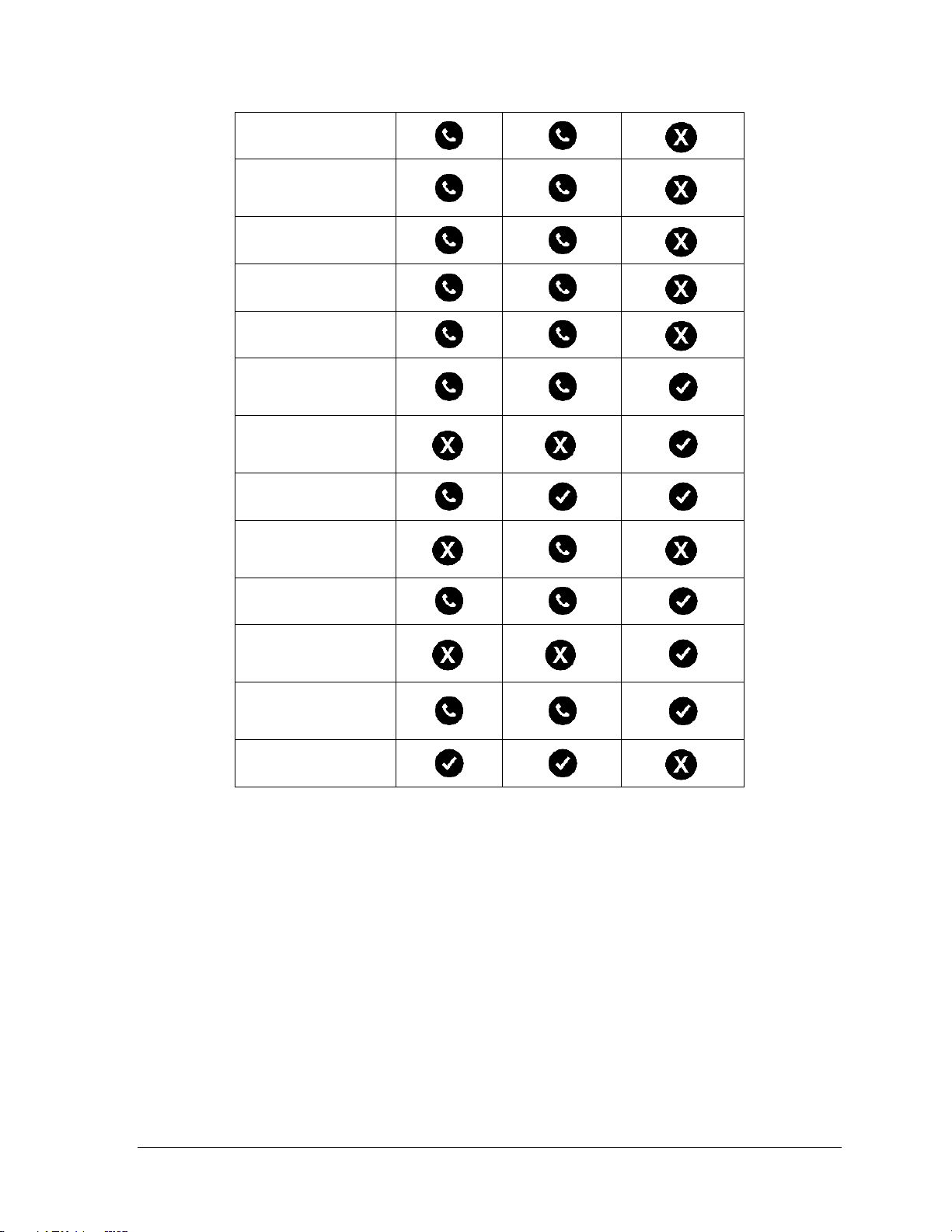
Foam (top of foam
Foam (top of foam
measurement)
Coating/tack y liquids
Crystallizing liquids
Viscous liquids
Probe is close to
objects (<12″/30cm)
Probe could contact
disturbing objects
Turbulent Surface
Turbulent fluid
stress on probe
Tall, narrow nozzles1
Liquid or vapor
probe above surface
Disturbing
interference in tank
Ability to clean
measurement)
and liquid surface
tank wall/disturbing
tank wall, nozzle or
causing mechanical
spray could contact
electromagnetic
probe
1
See the SLG 700 SmartLine Guided-Wave Radar Level Specification, Document
#34-SL-03-03.
Revision 9 SLG 700 SmartLine Level Transmitter User’s Manual Page 5
Page 22
1.4 Communicating with the Tr a ns mi t t er
It is possible to remotely monitor and configure a transmitter using either the HART or
TM
FOUNDATION
transmitter can be monitored using the analog current, and with both interfaces, can be
configured using the three-button interface and display.
Note:
4-20 mA HART
The output of a transmitter configured for the HART pro to co l includes two primary modes:
• Point-to-Point Mode: one transmitter is connected via a two-conductor, 4-20mA
current loop to one receiver.
• Multi-Drop Mode: several transmitters are connected through a two-conductor
network to a multiplexed receiver device.
The major difference between the two modes is that in Point-to-Point mode, the average
value of the loop current represents the current value of an analog signal representing the
process inside the tank. In multi-drop mode, the average value of the loop current is fixed,
usually at 4mA. Therefore, in Point-to-Point mode, an external control system can read the
Primary Variable (PV) through an analog input without HART messaging, whereas in multidrop mode, the PV can only be read as a digital value using HART messaging.
Fieldbus (FF) protocols. Alternatively, with the HART option, the
The protocols are not interchangeable. Each protocol uses
significantly different terminal and communication boards that are
installed before shipping.
Note: In the HART system, the abbreviation PV is used to denote the
Primary Variable which may be only one of a number of process or
device variables that may be available.
SLG 700 supports HART version 7 and its associated backward compatibility. The analog
signal is modulated by Frequency Shift Keying (FSK), using frequencies and current
amplitude that do not affect analog sensing at the receiver. The accuracy of the analog level
must be precisely controlled for accurate sensing. HART communication will not bump
process variables. In multi-drop mode, theoretically up to 16 devices in HART 5 (addresses
0-15) or up to 64 devices in HART6/7 (add resse s 0-63) can exist on the two-conductor
network. Practically, the number of devices in a multi-drop installation is limited due to
design constraints. When installing into a multi-drop network, consider that the SLG700
requires a minimum startup current of 17mA and a minimum terminal voltage of 11V during
startup. After this initial startup period (approximately 0.5 seconds), the loop current will be
fixed at 4mA, and the minimum terminal voltage is 14V. The power source, wiring, intrinsic
safety barriers, and other devices in the network be considered to ensure these requirements
can be met.
Note: The SLG700 requires a minimum startup current of 17mA, even when configured in
multi-drop mode. The minimum terminal voltage is 11V during startup. After startup, the
loop current will be fixed at 4mA, and the minimum terminal voltage should be 14V.
Page 6 SLG 700 SmartLine Level Transmitter User’s Manual Revision 9
Page 23
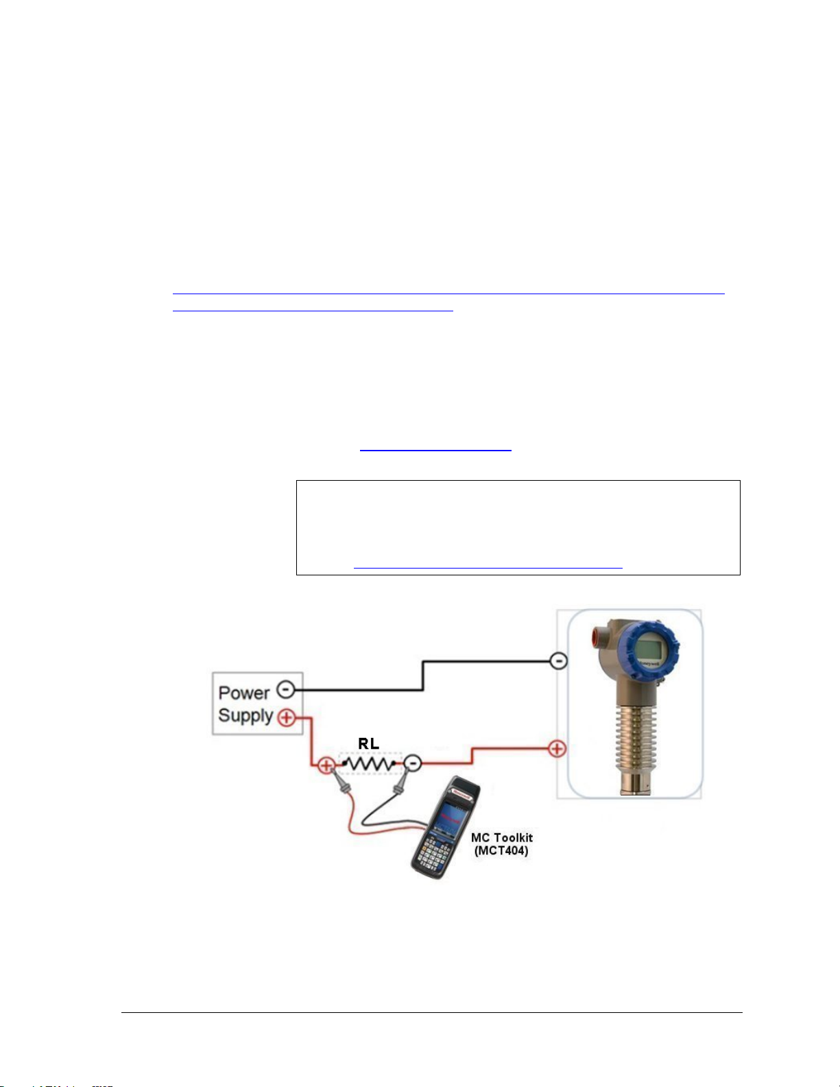
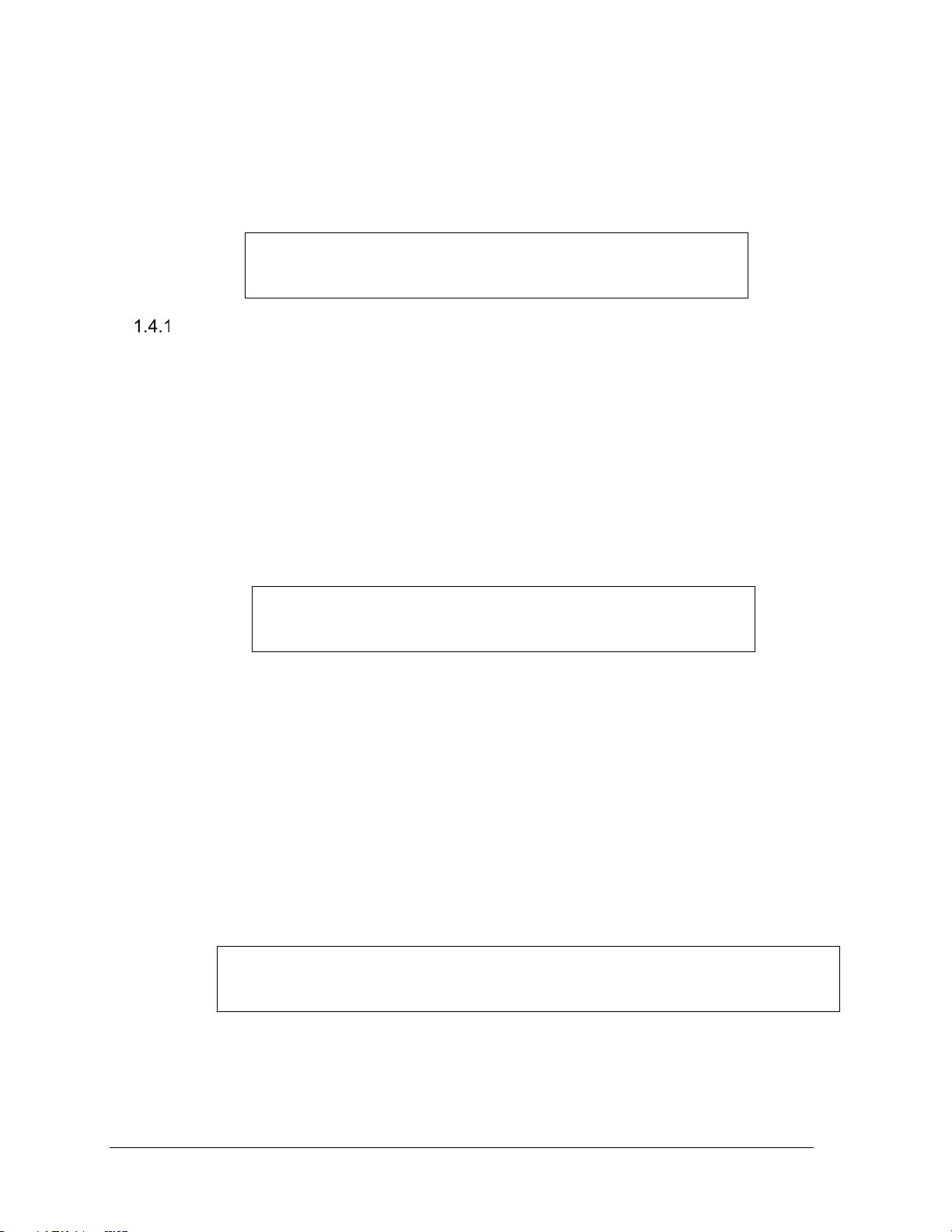
Figure 2-2 is an example of a HART connection to the transmitter. The communication
resistor RL may be inserted anywhere in the 4-20 mA loop but it is recommended to be
installed close to the positive supply. Refer to section 0 for acceptable power supply and RL
ranges
The MC Toolkit is a dedicated Honeywell communication tool that uses Device Description
(DD) files to communicate with multiple transmitter models. Also, other equ ivalent tools or a
HART-to-USB converter may be used. Device Desc rip tion fi le s are availab le from:
• HONEYWELL: Go to:
https://www.honeywellprocess.com/en-US/explore/products/instrumentation/process-levelsensors/Pages/smartline-level-transmitter.aspx
Select the “Software” tab.
Scroll/search for file name:
“HART Device Description (DD) files for Honeywell HART Devices”
This .zip file contains the latest version of the DD files for all of Honeywell’s HART field
devices.
Unzip the file to locate the DD files applicable to the SLG 700 series.
®
• HART
FOUNDATION: http://en.hartcomm.org
Device Descriptions (DD) are HART data files which are
gathered from field device manufacturers which describes the
Note:
features and functions of a device.
HART provides a detailed definition here:
http://en.hartcomm.org/hcp/tech/faq/faq.html
Figure 2-2: Example of HART connection RL
Refer to section 0 for RL information
Revision 9 SLG 700 SmartLine Level Transmitter User’s Manual Page 7
Page 24
FOUNDATIONTM Fieldbus (FF)
The Honeywell SLG 700 is a SmartLine Level transmitter that has a wide range of additional
features along with supporting the FOUNDATION
TM
Fieldbus (FF) communication protocol.
The SLG 700 level transmitter with FF protocol provides a FOUNDATION Fieldbus
interface to operate in a compatible distributed Fieldbus system. The transmitter includes
FOUNDATION Fieldbus electronics for operating in a 31.25 Kbit/s Fieldbus network and
can interoperate with any FOUNDATION Fieldbus registered device.
The Honeywell SmartLine SLG 700 is a high-performance transmitter offering high
accuracy, reliability and resolution over a wide range of process conditions.
The SLG 700 Fieldbus device is fully tested and compliant with Honeywell Experion® PKS
providing the highest level of compatibility assurance and integration capabilities.
Figure 2-3 graphically represents the connection of the transmitter to a FF handheld device. A
similar connection may be realized using PC configuration software.
Each transmitter includes a configuration database that stores its operating characteristics in a
non-volatile memory.
The handheld or PC software is used to establish and/or change selected operating parameters
in a transmitter database. The process of viewing and/or changing database parameters is
called configuration.
Configuration can be accomplished both online and offline with the transmitter powered up
and connected to the handheld.
Online configuration immediately changes the transmitter operating parameters. For offline
configuration, transmitter operating characteristics are entered into the handheld memory for
subsequent downloading to transmitter.
Figure 2-3: Example of FF connection
Page 8 SLG 700 SmartLine Level Transmitter User’s Manual Revision 9
Page 25

DTM-based tools and Experion
HART and FOUNDATION Fieldbus models support Device Type Managers (DTMs)
running on Field Device Technology
Manager (FDM) / Experion.
The transmitter establishes communication with the host systems using DD or DTM.
Device Description (DD)
DD is a binary file that provides the definition for parameters in the FBAP of the
transmitter. For example, DD refers to the function blocks that a transmitter contains, and
the corresponding parameters in the blocks that are critical to the interoperability of
Fieldbus devices. They define the data required to establish communications between
different Fieldbus devices from multiple vendors with control system hosts. The DD
provides an extended description of each object in the Virtual Field Device (VFD).
The Fieldbus Foundation provides the DD for all registered devices on its website,
http://www.fieldbus.org/index.php?option=com_mtree&task=viewlink&link_id=1991&ff
bstatus=Registered&Itemid=324
®
(FDT) hosts such as PACTware or Field Device
Revision 9 SLG 700 SmartLine Level Transmitter User’s Manual Page 9
Page 26

Enhanced Device Description (EDD)
There are two types of EDDs are available, namely .ff5/.sy5 and .ffo/sym. The .ffo/.sym
binary files are generated for the legacy hosts to load the dev ice DD that is generated using
latest tokenizer. Few constructs like Images that are supported in .ff5/.sy5 binaries, are not
supported in .ffo/.sym binary files.
Device Type Manager (DTM)
The DTM is similar to a device driver that enables usage of devices in all the asset
management and device configuration software like FDM or PACTware, with the help of the
FDT-DTM technology.
The DTM has the following primary functions:
• Provides a graphic user interface for device configuration.
• Provides device configuration, calibration, and management features for the
particular device.
The DTM provides functions for accessing device parameters, configuring and operating the
devices, calibrating, and diagnosing problems.
Download the DTM from:
https://www.honeywellprocess.com/enUS/explore/products/instrumentation/process-level-sensors/Pages/smartline-leveltransmitter.aspx
Go to the Software tab
To set up the DTM on the FDM/Experion refer to the FDM/Experion User Guide.
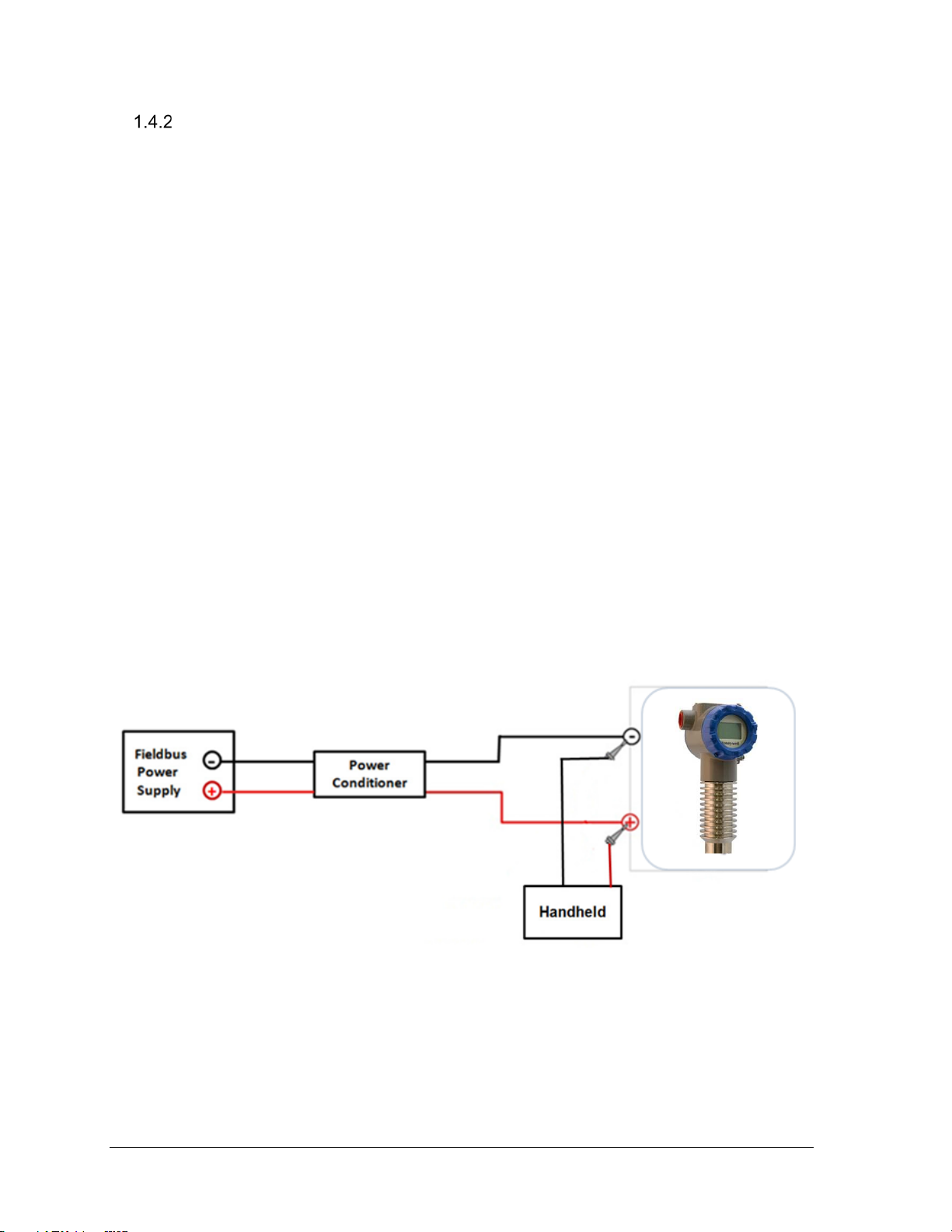
Figure 2-4 shows an example of a FF network setup.
For more information on Experion go to:
https://www.honeywellprocess.com/integrated-control-and-safety-systems/experion-pks/
Page 10 SLG 700 SmartLine Level Transmitter User’s Manual Revision 9
Page 27
Figure 2-4: Example of a FF network
1.5 SLG 700 Transmitter nameplate
The Transmitter nameplate is mounted on the top of the electronics housing
(see Figure 2-5) and lists the following properties:
• Model number
• Physical configuration
• Power supply voltage
• Maximum working pressure rating
• Certification, if ordered (SIL and CRN)
Revision 9 SLG 700 SmartLine Level Transmitter User’s Manual Page 11
Page 28
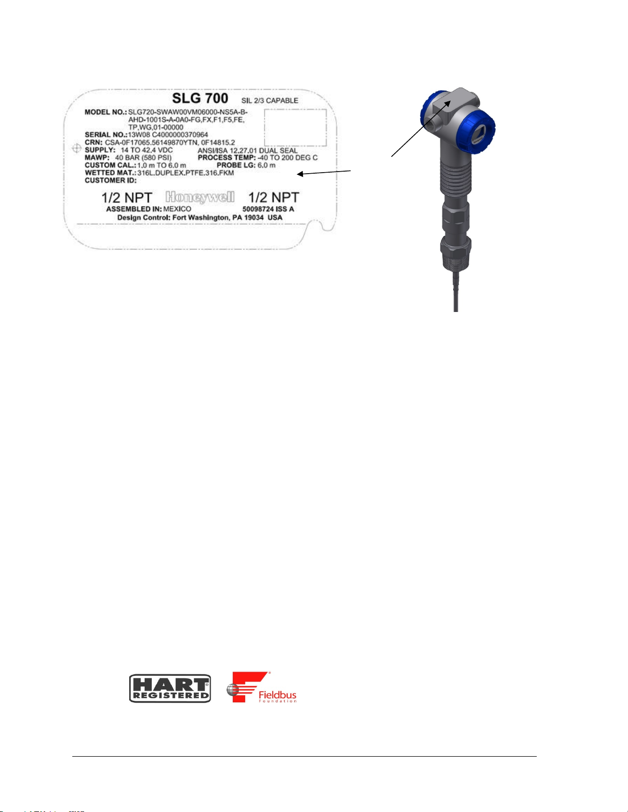
Product ID
Nameplate
Figure 2-5: Transmitter nameplate example
The nameplate contains the following information:
MODEL NO.: The transmitter model number per the model selection guide.
SERIAL NO.: The unique transmitter serial number.
CRN: The CSA Registration number.
SUPPLY: The DC power supply voltage range as measured at the terminal assembly.
MAWP: Maximum Allowable Working Pressure.
PROCESS TEMPERATURE: The Process temperature range.
CUST. CAL.: Specifies any custom calibration, if ordered, otherwise blank.
PROBE LG: Length of the probe as defined in the model number.
WETTED MATERIAL: A list of the wetted materials.
CUSTOMER ID: User-defined identifier, if ordered, otherwise blank.
HOUSING CONNECTION TYPE: Conduit fitting size: ½” NPT or M20
ASSEMBLED IN / MADE BY HONEYWELL: The country where the transmitter was
assembled and tested.
SIL INFORMATION: SIL 2/3 Capable is indicated if SIL certification applies, otherwise blank.
COMMUNICATION INTERFACE: A symbol indicating the supplied communications
interface, HART or FOUNDATION Fieldbus.
or
Page 12 SLG 700 SmartLine Level Transmitter User’s Manual Revision 9
Page 29
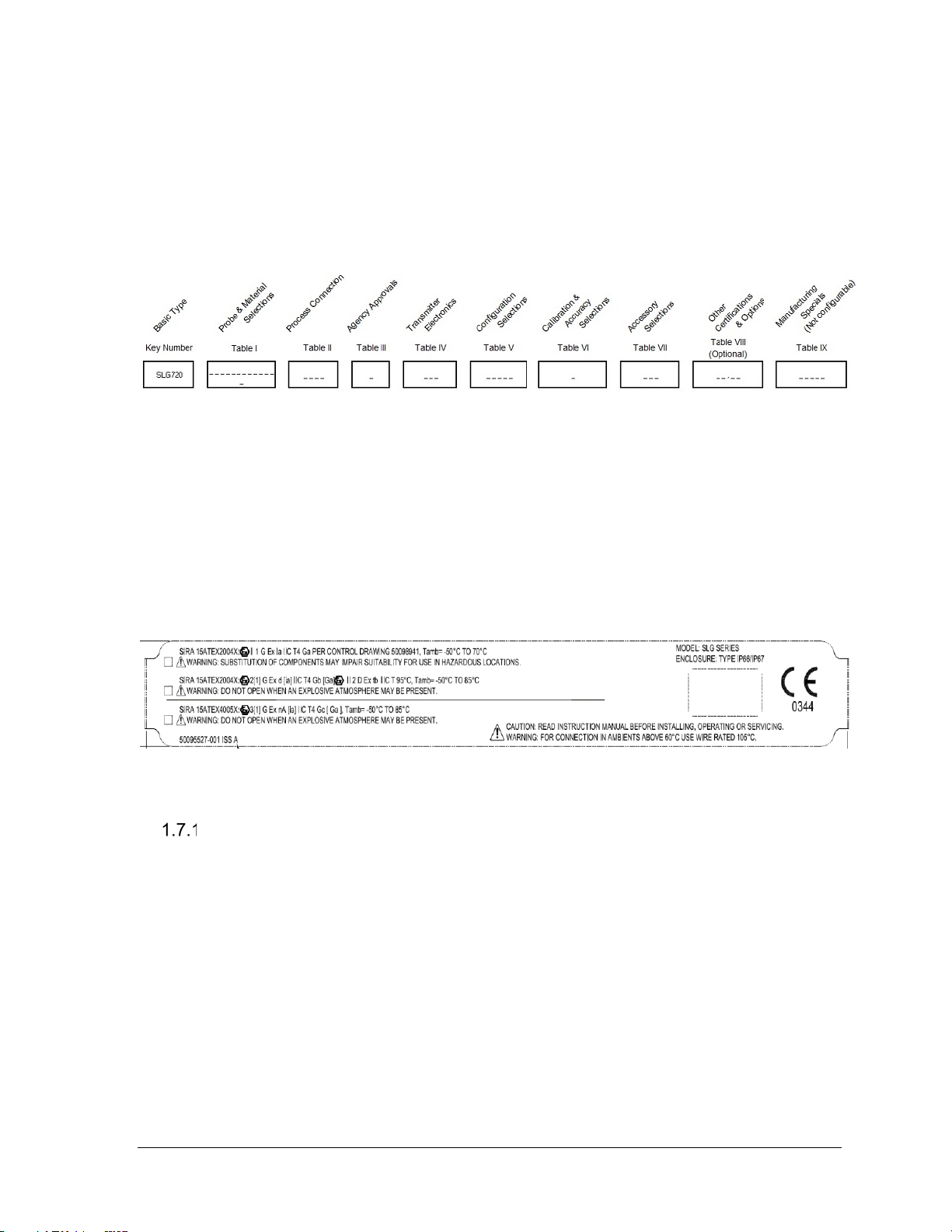
1.6 Transmitter Model Number De s cri pt ion
The model number is comprised from a number of selections and options that can be specified
when ordering the transmitter. It includes a basic transmitter type such as SLG720 (standard
temperature, standard pres s ure) followed by a maximum of nine additional character strings
that can be selected from a corresponding Table in the Model Selection Guide (MSG).
The basic model number structure is shown in Figure 2-6.
Figure 2-6: Standard SLG 700 Model Number
For a more complete description of the various configuration items and options, refer to the
SLG 700 Product Specification (34-SL-03-03) and Model Selection Guide (34-SL-16-01).
1.7 Safety Certification Information
SLG transmitter models are available for use in hazardous locations, including CSA, IECEx,
ATEX, and FM approvals. See Appendix Certifications for details and other approvals. The
transmitter will include an “approvals” nameplate mounted on the electronics housing with the
necessary compliance infor m ation.
Figure 2-7: Safety certification example
Safety Integrity Level (SIL)
The SLG 700 is intended to achieve sufficient integrity against systematic errors by the
manufacturer’s design. A Safety Instrumented Function (SIF) designed with this product must
not be used at a SIL level higher than the statement, without “prior use” justification by the
end user or diverse technology redundancy in the design. Refer to the SLG 700 Safety Manual,
Document #34-SL-25-05, for additional information. The SIL level will be indicated on the
SLG 700 nameplate.
See the SLG 700 Transmitter nameplate for additional information, Figure 2-5.
Revision 9 SLG 700 SmartLine Level Transmitter User’s Manual Page 13
Page 30

1.8 Security Considerat ions
The SLG 700 provides several features designed to prevent accidental changes to the device
configuration or calibration data. These features include a local display password (HART
option), a communication password (HART option), a Hardware Write Protect Jumper and a
Software Write Protect configuration parameter. These features can be used in combination to
provide multiple layers of change protection.
For both the local display and communication passwords, the initial user passwords are
defined as "0000". A "0000" password indicates that the user has not set a user- defined
password and the password protection is disabled. The password used on the local keyboard
display is separate from the password provided for communication. Password protection from
the local keyboard display does not inhibit changes by way of communication over the current
loop. A master password is available that allows recovery if the set user password is unknown.
A hardware write-protect locks out changes regardless of the entry of a password. The
hardware jumper requires phy sical access to the dev ice as well as partial disassembly and
should not be modified where the electronics are exposed to harsh conditions or where unsafe
conditions exist. For configuration or calibration changes without changing the hardware
jumper position the user may choose to rely on the password and software lockout features.
A tamper mode feature (see SLG 700 SmartLine Guided Wave Radar Level Transmitter HART
Option Manual, Document #34-SL-25-06) is available that can indicate that an attempt was
made to change either the configuration or calibration of the device (whether or not a change
was actually made). These security features are designed to avoid accidental changes and to
provide a means to detect if an attempt was made to change the configuration and calibration.
Note: FF does not support tamper mode.
1.9 Measurement Options Li c e nsi ng
As of software revision R200, the sensor checks whet her the user has a licen se req uired to
operate the device in a particular measurement mode (see also 2.5 for the various
measurement modes). Licenses are required to measure two-liquid interfaces, use the low
DC measurement mode and for steam applications. Any sensor ordered for these application
will have a valid license key stored in the transmitter and no user action is required.
The license key depends on the device ID which can be checked using the display (see
Table 4-8 or DTM. It is possible to obtain new license keys for application types other than
which the gauge was originally bought for by supplying the device ID to Honeywell and
entering the newly obtained license key.
Gauges that were installed prior to R200 do not lose access to the interface measurement
when they are upgraded to the new software - the sensor will internally generate a license key
for this applica tion after the first startup and store it in memory.
Page 14 SLG 700 SmartLine Level Transmitter User’s Manual Revision 9
Page 31

2 Radar Level Measurement
2.1 Overview
This chapter describes the theory of operation of the transmitter and discusses how
measurements are affected by tank and process conditions.
2.2 Theory of Operation
Guided wave radar provides level measurement based on the Time-Domain Reflectometry
(TDR) principle. Electromagnetic measurement pulses are guided to the measured material by a
metallic probe. When the pulses reach a product surface or interface, a portion of the pulse will
propagate through the surface and the rest will be reflected backwards. The same probe
transports the reflected pulses from the measured material back to the transm itter.
The SLG 700 uses many very-low-power pulses with a technique called Equivalent-Time
Sampling (ETS) to efficiently extract level information. Figure 2-2 is an example of a
waveform acquired with the ETS method. The levels can be extracted from waveforms
knowing the expected positions and shapes of the flange, surface or interface, and end of probe
reflections.
The electromagnetic measuring signal travels at the speed of light for the medium in which it is
propagating in and the probe on which it propagates.
The pulse speed will be less than the speed of light in air by an amount which can be calculated
knowing the ‘dielectric constant’ of the material.
The transmitter measures the time of travel of the reflected signal and calculates distance to the
reflection point. The level of the material can be calculated based on the distance from the
transmitter to the material and the dimensions of the container as illustrated in Figure 2-1.
Distance to Surface calculation:
×
=
Where:
= Distance to surface
d
S
t = time for the pulse to tra vel distance, dS
= speed of light in a vacuum on the probe
v
wg
= dielectric constant of the material in the head space above the level
DC
V
(for air, DC = 1)
2×DC
Revision 9 SLG 700 SmartLine Level Transmitter User’s Manual Page 15
Page 32

DCv =
= Dielectric Constant of Vapor
DCU = Dielectric Constant of Level (Upper Product)
DC
= Dielectric Constant of Interface (Lower Product)
L
Figure 2-1: GWR measurement
Page 16 SLG 700 SmartLine Level Transmitter User’s Manual Revision 9
Page 33

TDR for Interface and Flooded Measurements
The Time -Domain Reflectometry (TDR) principle can also be us ed to m easure an Interface
Level as well as the upper level. The position of the level interface has to be calculated with
knowledge of the dielectric constant (DC
) of the upper layer.
U
The SLG 700 can measure levels of different materials in the same tank and can detect the
echo from the boundary between Vapor and the Upper Product (UP), and between the Upper
Product (UP) and the Lower Product (LP). This allows calculating the level for each material
and the interface thickness as in Figure 2-3.
If an interface level is being measured, the pulses pass through the upper medium before
reaching the interface.
Distance to Product in the Interface equation:
×
=
+
2 ×
Where:
dS = Distance to surface
∆t = change in time for a pulse to travel the distance through the Upper Product
= speed of light in a vacuum on the probe
v
wg
= Dielectric Constant of Upper Product
DC
U
Surface and interface measurements can be made if:
= where the DC Upper Product is less than 9 and the DC difference between the
DC
U
upper and lower product is greater than 8.
The minimum thickness of the interface layer is 7cm.
Figure 2-2 shoes the distances to surface and interface can be calculated as shown in this
sample echo curve.
Figure 2-2: Sample Echo Curve
Revision 9 SLG 700 SmartLine Level Transmitter User’s Manual Page 17
Page 34

Figure 2-3: Interface measurement
2.3 Signal processing configuration
SLG 700 series level transmitters employ advanced signal processing techniques in order to
get the most accurate measurements possible.
Complete pulse-shape information including amplitude, width and side-lobe attenuation is
used for level detection in order to minimize the influence of signal interferences. A typical
pulse and the associated parameters is shown on Figure 2-4.
The sensor is programmed with default values for all parameters, determined by the dielectric
constants of the materials being measured. Either through the advanced display or using the
Honeywell DTM (SLG 700 HART option manual 34-SL-25-06) these parameters can be
adjusted to match the measurement conditions. Typically, the amplitude (also referred to as
gain) of the model is the only parameter that needs to be adjusted, and this is generally only
required if the dielectric constant of the medium is uncertain. No te that the ‘attenu ati o n’
parameter of the model should not be confused with the attenuation of the radar pulse as it
propagates down the waveguide.
Page 18 SLG 700 SmartLine Level Transmitter User’s Manual Revision 9
Page 35

Figure 2-4 Radar Impulse Reflection model
Although the algorithms are tolerant of signal amplitude variation, a good match is important
to discern the true level signal from that caused by obstacles near the probe or secondary
reflections. Both the DTM and the advanced display module show the signal quality, a
measure of the match between radar pulse model and acquired echo curve.
Amplitude Tracking
Release R102 introduced an additional feature to improve level tracking under difficult
conditions or when the medium attenuation is not well known. The amplitude tracking feature
(off by default) enhances the user specified pulse model information using historical
measurement data. It can improve the quality of the match when there are slowly varying
conditions in the tanks, such temperature variations, vapor density changed, turbulence or
even dirt build up on the probe. Amplitude tracking is not a substitute for model tuning and
will not track signals more than 35% different in amplitude from those expected. It should be
noted that tracked amplitudes are periodically saved to permanent memory. When the sensor
starts up it will first attempt to locate the levels using the tracked signal amplitudes and if this
fails, will revert to the initial amplitudes when the sens or loses pow er sin ce it is impossible to
predict whether the conditions that caus ed the pulse to change (say turbulence) exist when the
sensor is repowered.
Full-tank Detection
This feature enables the transmitter to perform additional analysis on the data in the region
near the reference plane where the product refle ct ions become mixed with reflections from
the physical mounting components such as a flange or nozzle. This additional analysis allows
the transmitter to detect the presence of product in this region even if the shape of the product
reflections deviate significantly from the expected shape. This option should only be enabled
if a recently captured Field or Obstacle background is in use and the Dielectric Constant of
the Upper Product is above 12. It should not be enabled for products with low Dielectric
Constants or when the Built-in background type is being used.
Revision 9 SLG 700 SmartLine Level Transmitter User’s Manual Page 19
Page 36

Maximum Fill Rates, Latching and Timeouts
The maximum fill rate, also referred to as Rate of Change (ROC) limits the expected level
changes between two successive measurements. Software revision prior to R200 allowed a
range of 4 - 20 cm/s. As of R200 this limit is increased to 90 cm/s. If a level is detected to
have moved further then the ROC limit, the level status is considered bad. See also Table 4-5:
Display Config sub-menu.
The Echo Lost Timeout setting is the number of seconds that the transmitter will wait after
the reflection from the product has been lost before setting a critical alarm and entering
failsafe (burnout) mode. The sam e behavior w ill resu lt if instead of the measurement being
completely lost, the rate of change has been exceeded.
The latching mode parameter allows selecting the behavior of the GWR transmitter in case of
a measurement fault critical error. If the Latching option is selected, the GWR transmitter
will stay in the critical error state once the Echo Lost Timeout has expired, unti l a user
performs a hardware or software reset. Th e latching mode option has a significant effect on
behavior of the sensor when levels are considered lost. If the Non-latching option is selected,
the GWR transmitter will leave the critical error state automatically (after the Echo Lost
Timeout expires) and attempt to re-measure level over the entire probe length. Latching mode
can only be enabled with HART transmitters.
Page 20 SLG 700 SmartLine Level Transmitter User’s Manual Revision 9
Page 37

2.4 Signal Interferences and back ground echoes
Interfering reflections can occur near the top and bottom of the probe. These interfering
echoes occur or when the pulse encounters a transition, such as from nozzle to tank, or when
the pulse exits the process connector for a rod or wire probe, or when the pulse is reflected
from the end of the probe. Unwanted reflections can also occur, from deposits on the probe or
from interfering structures such as inlets, outlets, ladders and so forth, which are positioned
near the probe. If the user suspects deposits on the probe then it should be inspected and
cleaned, if necessary. The top and bottom zones in which these interferences occur can be
configured as blocking distances within which no measurement will occur.
Coaxial probes are less susceptib le to these in terfe renc es and have smaller upper blocking
distances. For all probes, the effects of interfering reflections near the process connector can
be reduced by background subtraction.
Release R102 offers two type of background echo acquisition modes and either can be
operated statically or dynamically.
Note that the Saturated Steam application is the only one which does not use background
subtraction.
Field and Obstacle background
The field background is meant to reduce the effect of the process connector reflection created
when the radar pulse traverses between two reg ions of dif ferent im pedance s. The pres et
length varies from 1.32m (standard temperature and pressure gauge) to 2.38m (high pressure
high temperature model) from the measurement reference plane (bottom of the process
connector). The user needs to ensure that the level in the tank is below these values when
acquiring the background. The field background is stored in permanent memory and can be
displayed using the Honeywell DTM or DD.
The obstacle suppression background can be used in place of the field background and is
intended to both suppress process connector reflections as well as any false echoes generated
by obstacles in the tank (ladders, pipes, valves) in the vicinity of the probe. There is no limit
on the length that can be specified by the user. As with the field background, the level in tank
needs to be about 20cm below the end of the requested echo. One difference between the
obstacle suppression echo and the field background echo is that the sensor algorithms analyze
this echo and store only those sections of the profile that are found to contain false echoes.
For example if a ladder exists 2m down a tank and a pipe inlet 19m down the tank, the user
should obtain an obstacle echo up to approximately 20m. The sensor will automatically
detect the two objects and permanently store the relevant data.
Static and Dynamic backgrounds
Release R102 introduced automatically updated background profiles. The intent of this
feature is to provide enhanced immunity against measurement conditions. With dynamic
backgrounds on, the sensor periodically schedules automatic updates to the background.
Echoes are only collected if the level is outside of the transition zones and the signal is of
good quality. Data is collected up to approximately 20 cm from the level at the time, if this
distance is within the requested background echo length.
Revision 9 SLG 700 SmartLine Level Transmitter User’s Manual Page 21
Page 38

The most recently updated background is also stored in permanent memory and is applied
after a sensor reset if dynamic background is enabled. At all times the sensor maintains a
copy of the original user-acquired (static) background echo and will revert to this if the
dynamic background feature is once again disabled. Re-enabling dynamic background at
that point starts the process anew. It is recommended that this feature is turned on in all
installations where build-up or ambient temperature swings over approximately 30°C (55°F)
are expected.
Accuracy and measurement range specifications
The available probe lengths for each probe type are summarized in Error! Reference source
not found.
'These accuracy specifications are defined under reference conditions, at other ambient
temperatures the accuracy specifications are increased by ±0.2 mm/°C or ±15 ppm/°C
whichever is greater.
The measurement accuracy over the probe length is the larger of ±3mm or ±0.03% of probe
length. At the top and bottom of the probe the measurement performance can deviate from
the ±3mm or ±0.03% accuracy specification.
The zones at the top and the bottom of the probe at which the accuracy deviates from the
accuracy spec is called upper and lower transition zones respectively.
As the level rises or falls in the upper and lower transition zone a point may be reach were the
transmitter cannot provide a level reading or the accuracy is worse than ±30mm, at this point
we have reach the minimum blocking distance that can be set in the transmitter.
Figure 2-7 to Figure 2-6 summarize the accuracy as a function of length for the available
probe types in addition Table 3-4 provides a tabular summary of the minimum blocking
distances and the transition zones. To meet the accuracy specifications near the end of the
probe (lower transition zone and minimum blocking distance low), the correct probe type and
probe length need to be configured.
Note that for a wire probe with an end weight or with a looped end the minimum blocking
distance low is measured from the top of the weight or the top of the loop’s crimp.
When the transmitter is installed in a nozzle then the di stan ces are measured from the bottom
on the nozzle, i.e. where the nozzle transitions to the tank. In addition, when using a nozzle
the guidance provided in Section 3.2.9.2 ne eds to be followed.
For the following four figures in this section, T
and T
up
are upper and lower transition
low
zones respectively.
Page 22 SLG 700 SmartLine Level Transmitter User’s Manual Revision 9
Page 39

Figure 2-5: Upper transition zone length and minimum blocking distance high (BDH)
and minimum blocking distance low (BDL) for coax probes in water.
Figure 2-6: Upper transition zone length and minimum blocking distance high (BDH)
and minimum blocking distance low (BDL) for coax probes in oil.
Revision 9 SLG 700 SmartLine Level Transmitter User’s Manual Page 23
Page 40

Figure 2-7: Transition zone lengths and minimum block ing distance high (BDH) for
single lead probes in water.
Page 24 SLG 700 SmartLine Level Transmitter User’s Manual Revision 9
Page 41

Figure 2-8: Transition zone lengths and minimum block ing distance high (BDH) for
single lead (i.e. rod and rope) probes i n oil.
Figure 2-9 Minimum blocking distances, steam application for a threaded HTHP
process connector
Revision 9 SLG 700 SmartLine Level Transmitter User’s Manual Page 25
Page 42

measurement
30 cm
47.0 cm
58.0 cm
50 cm
67.0 cm
78.0 cm
30 cm
44.5 cm
55.5 cm
50 cm
64.5 cm
75.5 cm
Note: BDH depends on threaded or flanged. Rods are either 30 or 50 cm. See Error! Reference
source not found.
Figure 2-10 Minimum blocking dista nce, steam application for a flanged HTHP process
connector
Process
connector type
Threaded
Flanged
Saturated Steam
Ref Length
Minimum BDH and distance from reference plane to top inlet depends on transmitter
configuration.
Note: these distances also apply to coax probes as we turn off the dynamic calculation when
the surface is closer than this value.
Table 2-1: Blocking Distance High
Minimum BDH Min dist to inlet or surface
with DC corrected
Page 26 SLG 700 SmartLine Level Transmitter User’s Manual Revision 9
Page 43

Interface accuracy and range
When measuring interface the accuracy of both the surface and interface level is ±3 mm and
the minimum interface thickness that can be measured is 7 cm. However, restrictions exist for
interface measurements depending on the application and on the dielectric constant (DC) of
the measured products:
- Maximum dielectric constant of the upper medium: 9
- Minimum dielectric constant of the lower medium: 10
- Minimum difference in dielectric constant between the upper and lower medium: 8
- Minimum upper product thickness: 7cm
In addition, the maximum upper product thickness that can be measured will be restricted by
the measured products. In the case of low absorption by the upper medium, upper product
thicknesses of greater than 30 meters can be measured. In contrast, in strongly absorbing
upper media, only upper product thicknesses of less than a couple of meters can be measured.
In general, absorption will tend to be higher in media with higher dielectric constant.
Therefore, the measurable thickness range of the upper product will be lower with higher
upper product dielectric constant applications (DC
When the upper product thickness drops below 15cm approximately, the surface and interface
reflections start to overlap. The transm it ter will continue to measure the upper product
thickness accurately down to 7 cm although the echo curve might only show one reflection
for both surface and interface. If the transmitter fails to measure upper product thicknesses
below 15 cm or if the measurement of thin interfaces is inaccurate, it might be necessary to
adjust the reflection models using the Honeywell DTM. Refer to the SLG 700 HART Option
manual, #34-SL-25-06 for details on adjusting model parameters.
Note: The level transmitter is designed to measure properly only when the upper product
thickness is greater or equal to 7 cm. For example, upon restart the transmitter will not
attempt to provide a surface and interface measurement if the upper product thickness is less
than 7 cm.
Note: If the surface level is never going to exceed the minimum blocking distance high (min
BDH) for the transmitter configuration, it is recommended to keep full tank detection option
off.
>3 or 4).
U
Revision 9 SLG 700 SmartLine Level Transmitter User’s Manual Page 27
Page 44

2.5 Process Applications
The SLG 700 Level transmitter is designed to work with a wide range of process
conditions. The sensor offers a total of 5 application modes:
Single Liquid
Two Liquids, flooded (only interface between to liquids is measured)
Two Liquids, non-flooded (surface and interface are both measured)
Steam Applications (sing le water-steam interface is measured)
Low-Dielectric Single Liquid Measurements (the end of the probe is
measured and the surface level is estimated from that and the DC).
New in R200 are Steam applications (discussed in Section 2.5.4) and the Low DC
Measurement. The latter is applicable when the dielectric of the medium is so low that barely
any of the radar pulse is reflected, see 2.5.2. Also new for R200 is that the applications other
than Single Liquid are licensed options, that is, a license key must be obtained from the
factory and entered into the transmitter before that application will become operational.
Single Liquid
The most common application is Single Liquid where only a distance to the upper surface
measurement is performed. It is possible that the dielectric of the air or gas above the
liquid has a different dielectric constant from unity, but in most conditions, the vapor DC
can be set to 1.
Measurements can be made in turbulent conditions or foaming conditions. However, in some
situations special precautions must be taken (see Section 2.6).
Two Liquid Applications
The flooded and non-flooded applications are both available with the same license key. The
flooded application is essentially a single surface measurement but in the case where a tank is
always fully filled with two liquids and the position of the inter face betw een then v aries. Th e
measured level is that of the interface.
Figure 2-11: Two-liquids Flooded
Page 28 SLG 700 SmartLine Level Transmitter User’s Manual Revision 9
Page 45

Figure 2-12: Two-liquids non-flooded.
Two-liquid non-flooded application ty pe is used in cases such as water beneath a
hydrocarbon in a separation tank. Both the top level and interface must be measured. The
low-DC material is assumed to be on top of the higher DC material. As of R200 this
application type is a pay-for-feature option; however, transmitters installed prior to R200 will
automatically generate a license for this application if the device is upgraded.
In two-liquid applications the dielectric of the upper liquid is required to measure the true
position of the interface between upper and lower fluid. Errors in this value result in error of
the interface and its thickness.
It is recommended that the Max Filling rate be set as low as is acceptable (say 0.1 m/s)
because it reduces the chance that the wrong echo is selec ted dur ing the processing of the
RADAR echo. Amplitude tracking should be turned on, especially if the attenuation of the
upper fluid is not well known.
Note that if the primary variable is either interface position or thickness, the sensor stops
reporting as soon as the surface has entered the set blocking zone. Surface measurements are
not made in the blocking zone but are required to measure the true position of the interface. If
the level moving into blocking zones is unavoidable, the sensor should be set to NonLatching mode (HART transmitters), where once the primary variable is lost, a new full
probe scan is triggered until the transmitter recovers.
When measuring interface the accuracy of both the surface and interface level is ±3 mm or
0.03%, whichever is greater, and the minimum interface thickness that can be measured is 7
cm. However, restrictions exist for interface measurements depending on the application and
on the dielectric constant (DC) of the measured products:
• Maximum dielectric constant of the upper medium: 9
• Minimum dielectric constant of the lower medium: 10
• Minimum difference in dielectric constant between the upper and lower medium: 8
• Minimum upper product thickness: 7cm
In addition, the maximum upper product thickness that can be measured will be restricted by
the measured products. In the case of low absorption by the upper medium, upper product
thicknesses of greater than 30 meters can be measured. In contrast, in strongly absorbing
upper media, only upper product thicknesses of less than a couple of meters can be measured.
Revision 9 SLG 700 SmartLine Level Transmitter User’s Manual Page 29
Page 46

In general, absorption will tend to be higher in media with higher dielectric constant.
Therefore, the measurable thickness range of the upper product will be lower with higher
upper product dielectric constant applications (DCU >3 or 4).
When the upper product thickness drops below 15 cm approximately, the surface and
interface reflections start to overlap. The transmitter will continue to measure the upper
product thickness accurately down to 7 cm although the echo curve might only show one
reflection for both surface and interface. If the transmitter fails to measure upper product
thicknesses below 15cm or if the measurement of thin interfaces is inaccurate, it might be
necessary to adjust the reflection models using the Honeywell DTM. Refer to the SLG 700
HART Option manual, #34-SL-25-06 for details on adjusting model parameters.
Note: The level transmitter is designed to measure properly only when the upper product
thickness is greater or equal to 7 cm. For example, upon restart the transmitter will not
attempt to provide a surface and interface measurement if the upper product thickness is less
than 7 cm.
Note: If the surface level is never going to exceed the minimum blocking distance high (min
BDH) for the transmitter configuration, it is recommended to keep full tank detection option
off.
For two-liquid non-flooded applications, the transmitter can simultaneously calcu late a
number of related parameters related surface and interface positions.
Low Dielectric Applications
R200 introduced a new measurement technique that can be helpful when the surface
reflection is either very small or otherwise unstable.
For any reasonably transparent medium, the sensor can detect the pulse reflected at the end of
the probe. Since the level of fluid influences the propag ation tim e for the radar pulse, the end
of probe signal will appear to recede as the tank fills. This apparent shift of the end of probe
signal is used to calculate the level of the surface.
However, this technique requires precise knowledge of both the probe length and the
dielectric constant of the medium. It is not recommended for regular single liquid
applications with dielectrics over approximately 2.5.
A procedure is available on the display or DTM to initiate an automatic probe length
calibration. This can be helpful in setting up this measurement mode and should of course
only be performed on an empty tank. Level measurement through the end-of-probe reflection
algorithm is a pay-for-feature option.
In some cases, this mode can provide level measurements whe re the sing le liqui d ap pl icati on
fails when excessive turbulence, foam or emulsions block the reflection from the surface but
still allow the end of probe to be detected by the transmitter. It should be noted that the
measurement accuracy when using this application type can be greater than the nominal ±3
mm possible with the other application types.
The end of the probe must be readily detectable for this method to work. In practice, this
means that rod and coax probe types are preferred as they produce bigger end reflections.
Wire probes with end weights are less preferred but still possible. Wire probes with other end
terminations are not recommended unless it is known that the end reflection is usable.
Additionally, surface reflections and material attenuation should be considered.
Page 30 SLG 700 SmartLine Level Transmitter User’s Manual Revision 9
Page 47

Usually, it will be the material absorption which determines the depth under which the end of
probe will be visible. This can be difficult to predict as published tables might not be correct
especially if there are material impurities or absorbed water present.
Steam Boiler Applications
Sensor revision R200 introduced a new application type: the measuremen t of the water level in
high-pressure steam boilers.
Unlike regular measurement applications where the user can enter a value for the dielectric
constant of the medium above the liquid, a measurement inside a boiler has a dynamic value of
the dielectric constant which varies with the steam pressure and temperature. To measure the
resulting varying speed of the radar pulse, the measurement rod is extended to include a
reference reflector that sits above the measurement area.
After installation but before the vessel is pressurized, the observed length of the probe to this
reference reflection is measured and recorded by the sensor. During subsequent measurements,
the apparent change in this distance is calculated and used to correct the propagation speed of
the radar pulse.
Steam applications always use the SLG726 (HTHP high temperature high pressure) process
connector with or without the 3-m remote housing extension. In all cases, the sensor uses a
reflection from the HTHP process connector as the reference plane from which all distances are
calculated. In total, therefore, the sensor must have four calibrated reflection models: the
internal reference from the sensor electronics, the process connector reflection mentioned
above, the steam reference reflection and the water sur face refl ect ion. While default model
values are supplied for all, it is highly recommended to use the DTM to display a typical echo
and verify that the model amplitudes are set correctly. If possible, verify that the process
connector model is still correct at the boiler operating temperature (amplitude tracking only
tracks level reflection echoes).
A typical example of an echo observed is shown below:
Figure 2-13 Typical Echo steam application echo with vapor reference rod
The transmitter probe type is restricted to coaxial or rod and the mounting location must be either
tank, for coax only, or bypass. In the case of a bypass, the diameter must be specified correctly. Note
the length of the steam reference rod should be calibrated after installation and before the vess el is
pressurized. This can be done from the display module or the DTM or the DD. Background
subtraction is not used for steam applications and it is advised that amplitude tracking be left on.
Revision 9 SLG 700 SmartLine Level Transmitter User’s Manual Page 31
Page 48

2.6 Process Condition Considerations
Process conditions can affect the way the surface appears to the GWR Transmitter.
Turbulence
Turbulence can result in the following measurement issues:
• The height of the surface reflection appears smaller.
• The level measurements display higher variability.
In extreme cases of turbulence, the surface level measurement can be lost entirely. To conteract these
effects, it is a good idea to enable amplitude tracking, and to increase the maximum fill rate
parameter. Alternatively, instead of a single liquid application type, if the dielectric constant is low
enough, measurements can be made with the Low DC application type.
Foam or Emulsions
Foam on the surface of the material being measured can influence the measurement. While light
foaming would have no influence at all, very heavy foam can degrade the measuring signal. Foam can
result in:
• The height of the surface reflection appearing smaller or even disappearing.
• Loss of accuracy due to an badly-defined surface.
Also in this case, amplitude tracking (See Section 2.3.1). or a Low DC application (see section 2.5.3).
selection can be attempted to counteract these problems.
FEP Probe
Revision R200 introduced FEP-coated probes for SLG720 transmitters (Standard Temperature
and Pressure). FEP is very similar in composition to PTFE. It has most of the excellent physical,
chemical, and electrical properties of PTFE, but with the ability to be processed using
conventional thermoplastics processing techniques. With FEP-coated probes, the only wetted
material is FEP. In addition to avoiding chemical compatibility issues between the process
connector or probe with the chemical process being monitored, FEP-coated probes may avoid
some potential build up issues, either because process chemicals are less likely to stick to FEP or
because there are no voids in which chemicals can accumulate.
The application types available are single liquid, two liquid with interface measurem ent, and the
low-DC algorithm type. Internally the sensor has algorithms to correct for the dispersion (change
in pulse shape) of RADAR pulses along such probes. Typically these effects are only visible for
probe lengths over about 10 m (33 ft.). It is important that the user correctly selects FEP-coated
probes (either rod or wire) when setting up the sensor. FEP applications are a pay-for-feature
option. Refer to the HART or FOUNDATION Fieldbus User's Manuals for further details of
advanced configuration with these probes.
Page 32 SLG 700 SmartLine Level Transmitter User’s Manual Revision 9
Page 49

2.7 Container Considerati ons
Shapes
The SLG 700 transmitter may be used in any shape of container. In general, it is designed to be
mounted vertically on top of the container, although angled mounting is also possible. See section
3.2.6 for angled mounting limitations.
Figure 2-14: Top vertical and angled mounting
Materials (plastic vs. metal)
The transmitter may be successfully used in containers made of any materials. When
planning the installation of the transmitter be aware that metal walls of the container
reflect the measuring signal and in some circumstances, may help amplify the useful
signal. Polymer walls of the container are transparent to the measuring signal. If the
transmitter is installed close to a polymer wall, the measuring signal may reflect from
metallic elements that are outside of the container. In addition, a transmitter installed very
close to a polymer wall may experience greater signal attenuation which can reduce the
measurement range of the instrument.
To mount a transmitter with threaded or small flange connection in a non-metallic
container an additional signal reflector is required. Refer to section 3.2.10
When the transmitter is installed in a non-metallic container a coax probe is recommended
if immunity to rad ia ted ele ctromagne tic fi elds (as per EN 61326 & IEC 61000-4-3) is
required.
Revision 9 SLG 700 SmartLine Level Transmitter User’s Manual Page 33
Page 50

2.8 Blocking distance high and blocking distance low guidance
The minimum blocking distances and accuracy in the transition zones may be compromised in
certain applications. In these cases and in order to meet the required specifications, it is
necessary to follow the guidance provided below. If the sensor performances in the transition
and blocking zones are compromised due to the presence of an obstruction and if the
performances cannot be improved, it is advisable to increase the configured blocking distances
accordingly. The latter will prevent the sensor from finding erroneous reflections in these
regions.
Blocking distance high (BDH) guidance
Meeting the minimum blocking distance high specification may require recording a field
background. A field background is captured when the tank is empty or when the tank
level is below the minimum required distance (See Section 2.4.2). The field background
records the reflected signal near the process connector. The background data is
subsequently removed from the echo curve that is used for analysis.
The length of the field background depends on the type of sensor, the length of the probe
and the length of the nozzle (if used). A field background may be automatically updated if
the Dynamic Background option is turned on.
Blocking distance low (BDL) guidance
To meet the blocking distance low specifications, the following three conditions apply:
• The probe type must be configured properly. For example, it is necessary to
indicate if a coax, a rod or a wire is used and what is the termination (end weight,
centering disk, etc.).
• The probe length must be configured accurately. The probe length is set at factory
time however if the probe has been cut or a centering disk was added it may be
necessary to reconfigure the probe length. See section 0 for details on centering
disks and configured probe length.
• In some cases, it might be necessary to adjust the end of probe model. For
example, if the end of probe is close to the bottom of the tank or to an obstacle, the
default end of probe model parameters might not be suitable. Refer to the SLG 700
HART Option manual, #34-SL-25-06 or the SLG 700 FOUNDATION Fieldbus
manual, #34-SL-25-07, for details on adjusting model parameters.
Blocking Distance, Full Tank Detection and Latching modes
When levels are lost into blocking zones the gauge display will report the level status as
uncertain, the level is reported as the blocking distance (rather than the actual level). A
digital indication will also be produced to indicate that the transmitter is detecting that the
level is in the blocking zone. Refer to the appropriate user's manual for details of interface
specific behavior.
Echos are generally not processed when the level is inside these zones except when Full
Tank Detection is turned on. When the level lowers outside of the upper blocking zone or
raises above the lower blocking zone, a small hysteresis distance is applied (2 cm and 3
cm for the upper and lower zones respectively) so that the sensor output remains
consistent as the level hovers near the blocking distance and does not toggle back and
forth between output states.
Page 34 SLG 700 SmartLine Level Transmitter User’s Manual Revision 9
Page 51

It is possible for the level to rapidly leave a blocking zone and exceed the maximum fill rate. Note
that the 'maximum fill rate' is the user-set maximum rate at which the level can change which will be
reported before a digital flag will be set. As discussed in 2.3.3, when the maximum fill rate is
exceeded, the transmitter considers the level lost and the gauge initiates the echo lost timeout counter
and sets the digital 'rate of change exceeded' flag. Software R200 differs from previous versions as to
the subsequent sensor behavior. In R200 and higher, depending on the latching mode settings, the
gauge will eventually initiate a new full probe scan and likely recover the level. Prior to R200, the
sensor would remain in the blocking zone until reset.
The maximum value for maximum fill rate is 0.9 m/s. 0.9 m is also close to the maximum amount
that the transmitter can detect a level change between two readings. If this value is exceeded the 'rate
of change' flag will not be set.
If the maximum filling rate is exceeded, the transmitter will continue to search for it in a narrow
region for it until the echo-lost timeout is expired. The transmitter will then enter a measurement fault
condition and search for the level over the entire probe length.
Note that if the rate of change is greater than a value greater than 0.9 m/s, the transmitter will likely
not track the level and only a level lost fault condition is set, without the ROC alarm. may not be able
to set a rate of change alarm. If the measurement is outside the blocking zones the transmitter will
display a measurement fault until the echo lost timeout period has been exceeded, and then it will
search for the level again. If it starts in a blocking distance position, it will stay in the blocking
distance until the level reappears within the distance allowed by the ROC limit0.9 m of the blocking
zone. However, as of R200, if the level appears suddenly outside of blocking distance, failing ROC a
level lost fault condition is set and output is maintained at the value of the blocking zone. This change
has important consequences if latching mode is not set.
Revision 9 SLG 700 SmartLine Level Transmitter User’s Manual Page 35
Page 52

Step
Action
See
Section
3.1 Preparation
Installation sequence
Table 3-1 lists the overall installation steps. Details are provided in th e indicated sections.
3 Transmitter Installation
Table 3-1: Installation seq u ence
1
2
Perform mechanical installation of transmitter and probe. 3.2
Connect transmitter wiring and po wer. 3.3
After Installa t ion check the transmitter’s configuration and tune if necessary. Transmitters
that were ordered using Honeywell’s SmartLine Application and Validation Tool (AVT) will
come with parameters pre-loaded so that the transmitter will giv e accura te lev el
measurements out-of-the-box. Refer to SLG 700 HART Option Man ual, #34-SL-25-06 or the
SLG 700 FOUNDATION Fieldbus manual, #34-SL-25-07.
Page 36 SLG 700 SmartLine Level Transmitter User’s Manual Revision 9
Page 53

For this item
(Model number signifiers)
Use this tool
Tools
Required tools depend on options ordered.
M3 set screw for Coaxial coupler (SCA ACA) AF1 1.5 mm Allen key
M4 set screw for Electronics Housing rotation AF 2.0 mm Allen key
M5 set screw for Wire probe end weight (SWA,
SWB)
Rod probe (8mm) (SRA, SRH, SRJ, SCA) AF 7 mm wrench
Rod probe and nut (12 mm) (SRB, SRM, SRN) AF 10 mm wrench
Rod probe (16mm) (SRK, SRL, SCB) AF 14 mm wrench
Saturated steam reference rod (22 mm) AF 20 mm wrench
Probe nut (8mm) (SRA, SRH, SRJ, SCA) AF 8 mm wrench
Probe nut (16mm) (SRK, SRL, SCB) AF 14 mm wrench
Saturated steam nut (22 mm) AF 20 mm wrench
Centering disk bolt (Wire probe) AF 17 mm wrench
Mounting thread ¾” and 1” (SLG720) (xx7A, xx1A) AF 40 mm wrench
Mounting thread 1-½” (SLG720) (xx5A) AF 50 mm wrench
Mounting thread 2” (SLG720) (Nx2A) AF 60 mm wrench
Mounting thread 1-½”, 2” (SLG726) (NS5A) AF 60 mm wrench
Coaxial probe outer process connector (SCA SCB)
AF 2.5 mm Allen key
Process compatible thread loc k ing
compound is recommended (for
example, Loctite 242)
Coaxial probe outer process connector (SCA, ACA)
Coaxial probe outer process connector (SLG726 /
SCB)
Rod and coaxial probe cut to length Metal saw
Wire probe cut to length Saw or bolt cutter
Drill hole in coaxial outer tube (SLG720) Drill and 6.0 mm drill bit
Remote mounting transmitter to bracket Phillips screwdriver
Retaining ring pliers for internal
diameter 20 mm
Retaining ring pliers for internal
diameter 40 mm
1
AF means across face referring to tool size.
Revision 9 SLG 700 SmartLine Level Transmitter User’s Manual Page 37
Page 54

Step
Action
See Section
3.2 Mechanical Installation
Follow the steps in Table 3-2. See Section 3.3.1 for wiring and configuration steps.
Table 3-2: Mechanical installation sequence
1
2
3
4
5
6
7
8
Check probe dimensions and strength. 3.2.1
Trim probe to correct length. 3.2.3
Attach/assemble the probe to the process connector. 3.2.4
Attach centering disk to probe if applicable. 0
Mount the transmitter. 3.2.6 & 3.2.7
Rotate electronic housing to desired view angle (on
models with optional display).
Secure the probe. 3.2.12
Install conduit entry plugs and adapters. 3.2.13
3.2.11
Check for correct probe dimensions and strength
Measure for correct probe length and check that your probe is within tensile or bending
load limits. See section 3.2.2.1 for details.
See Table 3-14: Probe length for different probe types
Accuracy and measuring range specifications
See section 2.4.3
Page 38 SLG 700 SmartLine Level Transmitter User’s Manual Revision 9
Page 55

Parameter
Description
Probe
Type
Min / Max Length
Materials
Minimum
High [cm]
Upper
[cm]
Minimum
Low [cm]
Lower
[cm]
Wire
Rod
Coax
Table 3-3: Sensor Details – All Models
Rod 0.4m (1.3ft) / 6.3m (20.7ft) SS 3161L, C-276*
Wire 1.0m (3.3ft) / 50m (164 ft) SS 316
Coax 0.4m (1.3ft) / 6.3m (20.7ft) SS 3161L, C-276*
*Only for model SLG720
Table 3-4: Minimum blocking distances and transition zones for the various probe
types.
Probe
Type
Rod/Wire
Rod/Wire
Coax
Coax
Media in
Tank
Water (DC=80)
Oil (DC=2)
Water (DC=80)
Oil (DC=2)
Blocking
Distance
9 13 0 1
7 14 0 12
5 14 2 0
5 8 6 7
Transition
Zone, T
up
Blocking
Distance
Transition
Zone, T
Table 3-5: Minimum blocking distances and Minimum distance to inlet or surface with
DC corrected level for the Saturated Steam Application.
Process
connector
type
Threaded
Flanged
Saturated
Steam Ref
Length
30 cm 47.0 cm 58.0 cm 7 cm
50 cm 67.0 cm 78.0 cm
30 cm 44.5 cm 55.5 cm
50 cm 64.5 cm 75.5 cm
Minimum BDH Min dist to inlet or
surface with DC
corrected
measurement
Minimum BDL
low
Table 3-6: Maximum measurement range for each probe type versus dielectric constant.
Probe
Revision 9 SLG 700 SmartLine Level Transmitter User’s Manual Page 39
Min DC Range Min DC Range Min DC Range
1.4 15m (49ft) 1.4 6.3m (21ft) 1.4 6.3m (21ft)
1.8 25m (82ft)
3 42m (138ft)
4 46m (151ft)
6 50m (164ft)
Page 56

Figure 3-1 SLG720 probe dimensions, mm [in]
Page 40 SLG 700 SmartLine Level Transmitter User’s Manual Revision 9
Page 57

Figure 3-2: SLG720 FEP probe dimensions, mm [in]
Revision 9 SLG 700 SmartLine Level Transmitter User’s Manual Page 41
Page 58

Figure 3-3: SLG726 Threaded process connection probe dimensions; mm [in]
Page 42 SLG 700 SmartLine Level Transmitter User’s Manual Revision 9
Page 59

Figure 3-4 SLG726 Flanged process connection probe dimensions; mm [in]
Revision 9 SLG 700 SmartLine Level Transmitter User’s Manual Page 43
Page 60

Figure 3-5: SLG726 Saturated steam application threaded process connection probe
dimensions; mm [in]
Figure 3-6: SLG726 Saturated steam application flanged p rocess connection probe
dimensions; mm [in]
Page 44 SLG 700 SmartLine Level Transmitter User’s Manual Revision 9
Page 61

Maximum
[kN]
1m (3′)
30°
2m (6′)
8°
4m (13′)
2°
6m (19′)
1°
Maximum Bending Torque
[Nm]*
Tensile load
Motion of the medium inside of the tank will impart load onto the probe of the transmitter.
Flexible wire probes will experience tensile loading that will be transferred to the roof of the tank.
Ensure that the maximum probe tensile load does not exceed maximum tank roof load. Depending
on position, forces on anchored flexible probes can be two to ten times greater than that of flexible
probes with end weights.
Table 3-7: Tensile load limits for flexible probe
Model
SLG720
SLG726
Probe
Selection
SWA, SWB,
PWA, PWB
Bending torque
Probe description
Wire, single, 4mm 5 15
Tensile Load Limit
[kN]
Roof Load
A vertically mounted rigid probe bends due to fluid motion force. An angle mounted
probe also bends from gravity. The mounting angle and total torque from these forces
must not exceed the limits in Table 3-8, Table 3-9 and Table 3-10. For excessive torque
conditions consider using a flexible wire probe instead.
Table 3-8: Rigid (i.e. rod and coaxial) probe mounting angle limits
Total probe length Maximum angle
Table 3-9: Rod probe bending torque limits (all lengths)
Revision 9 SLG 700 SmartLine Level Transmitter User’s Manual Page 45
Model Probe description
SLG720
SLG726 Rod 16mm 25
*For an angle mounted probe reduce these limits by 50% to allow for bending from gravity.
Rod 8mm or FEP-coated rod,
10 mm 4
Table 3-10: Coaxial probe bending load limits (all lengths)
Page 62

Model
Probe
Selection
Probe description
Maximum Bending
Torque [Nm]*
SLG720
SCA
Coax 22mm, 2m (6′) segments
50
M=cd ×
2
× v2 × d × L
f
L-
L
f
2
SLG726
*For an angle mounted probe reduce these limits by 50% to allow for bending from gravity.
SCB
Coax 42mm, 2m (6′) segments
100
To calculate your probe’s torque due to fluid motion use the following formula and check it
against the torque lim it s in Table 3-9 and Table 3-10.
Where:
M = Moment or torque
Friction factor
c
d =
ρ [kg/m3] = Density of medium
v [m/s] = Velocity of medium
perpendicular to probe
d [m] = Diameter of probe
[m] = Level of medium
L
f
L [m] = Probe length
Example torque calculation for 8mm rod probe:
Friction factor (c
Density (ρ) 1000 kg/m
) 0.9 (turbulent flow – High Reynolds number)
d
3
(water)
Probe diameter (d) 0.008 m
= L (worst case)
L
f
These values yield the torque curves in Figure 3-7: Example bending torque values. For
example, if the 8mm rod probe is a total length of 4m (two 2m segments) then by checking
Table 3-9 you find probes with 2m segments have a torque limit of 4.0Nm limit, which will be
exceeded if fluid velocity is 0.4m/s, therefore you would need to use a coaxial or wire probe
instead. If the same 8mm rod probe is angle mounted then the limit is half of 4.0Nm, or
2.0Nm, therefore fluid velocity of 0.3m/s exceeds this limit.
Page 46 SLG 700 SmartLine Level Transmitter User’s Manual Revision 9
Page 63

Step
Action
1
2
3
4
5
Bending Torque [Nm]
Bending Torque [M] on 8mm rod probe
v=0.2m/s
v=0.3m/s
v=0.4m/s
Probe length [L] in meters
Figure 3-7: Example bending torque values
Trim the probe length
CAUTION: The minimum Blocking Distance Low (BDL) and accuracy in
the low transition zone will be compromised if the BDL guidance is not
followed. See Section 2.4.3
Shortening a rod probe
Where clearance to the bottom of the tank is less than 0.4” (10mm), the rod must be
shortened.
Rod probes are supplied in segments. Cut on the terminating rod segment (the one with
the unthreaded end).
Shortening a wire probe
Wire probes are provided with an end weight that is not attached.
Loosen the set screws holding the end weight to the rope.
Remove the end weight from the rope.
Measure the required wire length and wrap some adhesive tape around the
wire at the cut location to help hold the wire strands together when cutting.
Use a hacksaw and make the cut.
Insert the wire back into the end weight and tighten the 3 set screws.
Shortening a SLG720 coaxial probe
Note: The coaxial probe trimming instruction applicable only to SLG720. For SLG726,
if a coaxial probe is not the specified length, contac t Honey well’ s Techni cal Assis tanc e
Center as a new probe could be required / ordered.
Revision 9 SLG 700 SmartLine Level Transmitter User’s Manual Page 47
Page 64

Step
Action
1
2
3
Technical Assistance Center (TAC): 800-822-7673 in North America or 1-602-313-5558
from the rest of the world.
Coaxial probe consists of inner rod and coaxial outer tube. To trim the
coaxial probe, both inner rod and coaxial outer tube need to be trimmed.
For trimming the inner rod, refer to rod probe trimming instruction detailed
above. Avoid trimming the internal thread region of the inner rod.
To trim the coaxial outer tube, start on the terminating segment (the one
with the unthreaded end). Mark and trim the outer tube to the same
amount as the inner rod. Avoid trimming the coupler region of the outer
tube.
Drill a 6mm hole through the end of the outer tube at location shown in
Figure 3-8: Drill 6-mm diameter hole at the position shown on the coaxial
outer conductor..
Figure 3-8: Drill 6-mm diameter hole at the position shown on the coaxial outer
conductor.
Attach/assemble the probe
CAUTION: To reduce the risk of damage from electrostatic
discharge, ensure the Electronic Housing is grounded
before lowering a probe into a tank.
Page 48 SLG 700 SmartLine Level Transmitter User’s Manual Revision 9
Page 65

Step
Action
Process Connector
Nut
Lock Washer
Rod Segment
Lock Washer
Stud
Rod End
Central Connector
Rod probe assembly
Rod probes are shipped in segments. The segments are attached to each other with a stud
and a lock washer.
Fully thread the nut onto the central conductor. Using a lock
1
2
Note: Tighten each rod connection point to the following torques:
• SLG720 6.0Nm (4.4ft-lbs)
• SLG726 15Nm (11ft-lbs)
Note: For flanged SLG726 models, ensure the nut does not intrude into the
process connector. See Error! Reference source not found. for more
information.
washer, thread the first rod segment on to the central conductor.
Torque the nut against rod probe and lock washer to secure the
connection.
Thread the stud into first rod segment end. Using a lock washer
thread the next segment onto the stud. Apply torque to secure
the connection.
Figure 3-9: Rod probe assembly
Revision 9 SLG 700 SmartLine Level Transmitter User’s Manual Page 49
Page 66

Step
Action
Figure 3-10: SLG726 flanged process connection, probe nut installation position, mm
[in]
Wire probe assembly
Wire probes can be supplied with an optional end weight.
Fully thread the nut onto the central conductor. Using a lock washer, thread the
wire swage on to the central conductor. Torque the nut against probe and lock
washer to secure the connection.
1
2
Note: For flanged SLG726 models, ensure the nut does not intrude into the bore of the
process connector. See Figure 3-10: SLG726 flanged process connection, probe nut
installation position, mm [in] for more information.
Note:
Tighten the wire stud and nut to the following torque:
• SLG720 6.0Nm (4.4ft-lbs)
• SLG726 15Nm (11ft-lbs)
If applicable, insert wire probe into end weight. Tighten the 3 set screws to
secure end weight to wire probe
Note: Torque set screws to 6Nm (4.4ft-lbs)
Page 50 SLG 700 SmartLine Level Transmitter User’s Manual Revision 9
Page 67

Process Connector
Nut
Lock Washer
Rope Probe
Set Screws
End Weight
Central Connector
Revision 9 SLG 700 SmartLine Level Transmitter User’s Manual Page 51
Figure 3-11: Wire probe assembly
Coaxial probe assembly
The coaxial probe consists of an inner rod conductor, surrounded by an outer tube shield.
The concentricity of the inner rod inside of the outer tube is maintained by spacers placed
along the probe length. Depending on the final length of the probe, the construction
method may differ.
Note:
For the flanged HTHP, when constructing the probe, the nut
should not intrude into the body of the process connector.
Page 68

Step
Action
Fully thread the nut onto the central conductor of the process connector. Place a
Note: Tighten rod connection point to the following torque:
• SLG720 6.0Nm (4.4ft-lbs).
Slip the coaxial outer tube over the rod and spacer and tighten to the process
Insert an end spacer into the end of tube. Align the holes in the end spacer with
Figure 3-13: SLG720 Coaxial probe assembly (single outer tube depicted).
SLG720
The inner rod is comprised of 1.0m rod segments and one rod end. Depending on the
length of the probe there may be 0 to 6 1.0m rod segments. As with the rod probe, the rod
segments are attached to each other by way of a stud and lock washer, see Figure 3-13:
SLG720 Coaxial probe assembly (single outer tube depicted). In the coaxial probe
construction, a spacer is placed at each joint, retained by the lock washer.
If the coaxial probe is 2.0 m or shorter it will come with a single outer tube. If the probe
length is longer than 2.0 m, the outer tube will be supplied in segments. There are three
types of outer tube segments:
• Starter segment: which has an internal thread to attach to the process connector.
• Extension segment: which has external threads on both ends.
• End segment: which has an external thread on one end.
Probes over 2.0 m in length will always have one “starter” and one “end” segment, along
with 0 to 2 extension segments in between. The tubes are connected to each other by way
of a threaded tube coupler. It is recommended to build the coaxial probe 2 m at a time.
That is, attach two 1.0 m rod segments together and slip an outer tube over the rod.
Repeat until the probe is fully assembled.
Refer to Figure 3-13: SLG720 Coaxial probe assembly (single outer tube depicted) for
the SLG720.
Probe Length ≤ 1.0m:
lock washer between the locknut and the rod segment and torque the nut against
1
2
the rod segment and lock washer to secure the connection.
connector.
Note: Tighten connection point to the following torque:
• SLG720 30Nm (22ft-lbs).
It is recommended that a process compatible thread locking compound
(i.e. Loctite 242) be used on the outer conductor threaded joints.
3
the holes in the outer tube and insert the 2 locking pins. Refer to Detail B of
Page 52 SLG 700 SmartLine Level Transmitter User’s Manual Revision 9
Page 69

Probe Length 1.0m to 2.0m
Step
Action
Fully thread the nut onto the central conductor of the process connector. Place a
Note: Tighten rod connection point to the following torque:
SLG720 6.0Nm (4.4ft-lbs)
Slide a spacer onto first rod. Connect the rod "end" segment to first rod us ing a
assembly (single outer tube depicted).
Note: Tighten rod connection point to the following torque:
SLG720 6.0Nm (4.4ft-lbs)
Slip the coaxial outer tube over the rod and tighten to the process connector.
Note: Tighten connection point to the following torque:
SLG720 30Nm (22ft-lbs)
It is recommended that a process compatible thread locking compound
(i.e. Loctite 242) be used on the outer conductor threaded joints.
Insert an end spacer into the end of tube. Align the holes in the end spacer with
3-13: SLG720 Coaxial probe assembly (single outer tube depicted).
Probe Length ˃ 2.0m
Step
Action
Fully thread the nut onto the central conductor of the process connector. Place
Note: Tighten rod connection point to the following torque:
• SLG720 6.0Nm (4.4ft-lbs)
Connect the rod segment to first rod using a spacer, a stud and lock washer
Note: Tighten rod connection point to the following torque:
• SLG720 6.0Nm (4.4ft-lbs)
lock washer between the locknut and the first rod segment and torque the nut
1
2
against the rod segment and lock washer to secure the connection.
•
stud and lock washer. Refer to Detail A of Figure 3-13: SLG720 Coaxial probe
•
3
4
•
the holes in the outer tube and insert the 2 locking pins. Refer to Detail B of Figure
a lock washer between the locknut and the first rod segment and torque the
1
2
nut against the rod segment and lock washer to secure the connection.
as shown in Detail A of Figure 3-13: SLG720 Coaxial probe assembly (single
outer tube depicted).
Slip the “starter” coaxial outer tube over the rod and spacers and secure to the
process connector using the M20x1 thread.
Note: Tighten connection point to the following torque:
3
• SLG720 30Nm (22ft-lbs)
It is recommended that a process compatible thread locking compound
(i.e. Loctite 242) be used on the outer conductor threaded joints.
Insert an end spacer into the end of tube. Align the holes in the end spacer
with the holes in the outer tube and insert the 2 locking pins. Refer to Detail B
4
of Figure 3-13: SLG720 Coaxial probe assembly (single outer tube depicted).
Revision 9 SLG 700 SmartLine Level Transmitter User’s Manual Page 53
Page 70

Figure 3-12: SLG720 Coaxial probe assembly (single outer tube depicted)
Figure 3-13: SLG720 Coaxial probe assembly (single outer tube depicted)
Page 54 SLG 700 SmartLine Level Transmitter User’s Manual Revision 9
Page 71

Revision 9 SLG 700 SmartLine Level Transmitter User’s Manual Page 55
Page 72

SLG726
The inner rod is comprised of 2.0m rod segments and one rod end. Depending on the
length of the probe there may be 0 to 3 2.0m rod segments. As with the rod probe, the rod
segments are attached to each other by way of a stud and lock washer. In the coaxial
probe construction, a spacer is placed at each joint, retained by the lock washer. Because
the spacers have closed sections, they must be slipped over the end prior to connecting
the following rod segment. If the coaxial probe is 2.0m or shorter it will come with a
single outer tube. If the probe length is longer than 2.0m, the outer tube will be supplied
in segments. There are three types of outer tube segments:
• Starter segment: which has an internal thread to attach to the process connector,
• Extension segment: which had external threads on both ends,
• End segment: which has and external thread on one end.
Probes over 2.0m in length will always have one “starter” and one “end” segment, along
with 0 to 2 extension segments in between. The tubes are connected to each other by way
of a threaded tube coupler. It is recommended to build the coaxial probe 2m at a time.
That is, attach one 2.0m rod segment and then place the tube over the rod. Slip a spacer
onto one of the ends of the rod and attach the next rod segment. Repeat until the probe is
together.
Tip: To ease assembly, construct the coaxial probe vertically, by suspending the
transmitter by the process connector on a hoist or crane.
Refer to Figure 3-14: SLG726 Coaxial probe assembly for the SLG726.
Page 56 SLG 700 SmartLine Level Transmitter User’s Manual Revision 9
Page 73

Probe Length ≤ 2.0m
Step
Action
Thread the nut onto the central conductor of the process connector. Refer to
the rod segment and lock washer to secure the connection.
SLG726 15Nm (11ft-lbs)
Slip the coaxial outer tube over the rod and tighten to the process connector.
Note: Tighten connection point to the following torque:
SLG726 30Nm (22ft-lbs)
It is recommended that a process compatible thread locking compound (i.e.
Loctite 242) be used on the outer conductor threaded joints.
Install end spacer between central conductor and outer tube in the
counterbore. Secure end spacer using the retaining ring.
> 2.0m
Step
Action
Thread the nut onto the central conductor of the process connector. Refer to
the rod segment and lock washer to secure the connection.
• SLG726 15Nm (11ft-lbs)
SLG726 30Nm (22ft-lbs)
It is recommended that a process compatible thread locking compound (i.e.
Loctite 242) be used on the outer conductor threaded joints.
Prior to securing the next rod segment, place a “star shaped” spacer over the
Note: Tighten rod connection point to the following torque:
the previous outer tube segment.
Note: Tighten connection point to the following torque:
SLG726 30Nm (22ft-lbs)
It is recommended that a process compatible thread locking compound (i.e.
Loctite 242) be used on the outer conductor threaded joints.
Figure 3-10: SLG726 flanged process connection, probe nut installation
for nut position on flanged process connectors. Place a lock
1
position, mm [in]
washer between the locknut and the first rod segment. Torque the nut against
Note: Tighten rod connection point to the following torque:
•
2
•
3
Probe Length
Figure 3-10: SLG726 flanged process connection, probe nut installation
position, mm [in]
1
2
washer between the locknut and the first rod segment. Torque the nut against
Note: Tighten rod connection point to the following torque:
Slip the "starter" coaxial outer tube over the rod and secure to the process
connection using the M40x1 thread.
Note: Tighten connection point to the following torque:
•
for nut position on flanged process connectors. Place a lock
3
rod segment end. The wrench flats on the rod end will index the spacer.
Depending on the probe length there could be 0 to 2 more rod segments and 1
rod "end" segment to assemble. Connect the subsequent rod segment to first,
4
using a stud and lock washer.
• SLG726 15Nm (11ft-lbs)
Slip a coaxial coupler over the last rod segment and spacer and tighten onto
5
•
Revision 9 SLG 700 SmartLine Level Transmitter User’s Manual Page 57
Page 74

coaxial coupler.
Note: Tighten connection point to the following torque:
It is recommended that a process compatible thread locking compound (i.e.
Loctite 242) be used on the outer conductor threaded joints.
segment remain.
step 3 above.
Attach rod "end" segment as in step 4 above.
Slip the coaxial coupler over the rod and spacer and tighten.
Note: Tighten connection point to the following torque:
SLG726 30Nm (22ft-lbs)
It is recommended that a process compatible thread locking compound (i.e.
Loctite 242) be used on the outer conductor threaded joints.
coupler.
Note: Tighten connection point to the following torque:
SLG726 30Nm (22ft-lbs)
It is recommended that a process compatible thread locking compound (i.e.
Loctite 242) be used on the outer conductor threaded joints.
bore. Secure end spacer using the retaining ring.
Insert 2 M3 set screws into each coupler.
Note: Tighten M3 set screws to 1.0Nm (8.8in-lb).
It is recommended that a process compatible thread locking compound (i.e.
Loctite 242) be used on each set screw.
Depending on probe length there may be 0 to 2 coaxial outer tube "extension"
segments and 1 coaxial tube "end" segment. Slip the next coaxial tube
"extension" segment over the last rod segment and spacer and tighten to the
6
• SLG726 30Nm (22ft-lbs)
7
8
9
10
11
12
13
Repeat steps 3-6 above until only the rod "end" segment and coax tube "end"
Attach the last "star shaped" spacer over the previous rod segment end, as in
•
Slip the coaxial end segment over the rod end segment and secure to coaxial
•
Install the end spacer between central conductor and outer tube in counter-
Page 58 SLG 700 SmartLine Level Transmitter User’s Manual Revision 9
Page 75

hardware
Figure 3-14: SLG726 Coaxial probe assembly
(Segm ented outer tube depicted)
Saturated Steam Application Probe Assembly
Saturated steam application is available with SLG726 rod and coax probes. The nut and first inner rod
segment have a larger diameter. The remaining hardware is identical. Refer to Error! Reference
source not found. for saturated steam hardware. To assemble the probes, thread the saturated steam
application nut to the central conductor, tap ered end tow ards the proc ess conne cto r. For flanged
process connectors, ensure the nut position is as shown in Figure 3-10: SLG726 flanged process
connection, probe nut installation position, mm [in]. Place a lock washer between the lock nut and the
steam reference rod. Torque the connection to 15Nm (11ft-lbs). Proceed with the standard assembly
procedures detailed above.
Revision 9 SLG 700 SmartLine Level Transmitter User’s Manual Page 59
Saturated
steam
Page 76

Figure 3-15 Saturated steam application rod probe assembly
Saturated steam hardware
Figure 3-16: Saturated steam ap plication coaxial probe assembly
Page 60 SLG 700 SmartLine Level Transmitter User’s Manual Revision 9
Page 77

Model
Thread
Probe
type
Recommended
probe diameter
Recommended probe material
No probe option
For those users who wish to supply their own rod or rope, the SLG 700 transmitter is
available with a no probe option (SLGXXX-000).
Note:
Users should not attempt to supply their own coaxial probes.
When this option is selected the transmitter will be supplied with a nut and lock washer,
but no probe. Recommended probe diameter and material of construction are shown in
Table 3-11. When the no-probe option is selec ted, Honey wel l does not guarantee
transmitter performance.
Table 3-11: Recommended probe diameter and material of construction
ASTM A-276, Type 316L,
condition A or ASTM B574 alloy
UNS N10276 solution
annealed.
ASTM A-276, Type 316L,
condition
SLG720 M5x0.8
SLG726
M10x1.5
Rope 4mm ANSI T316 (7x7 construction)
Rod 8mm
Rope 4mm ANSI T316 (7x7 construction)
Rod
16mm
Centering Disks and configured probe length
Centering disks are used to prevent the probe from contacting the wall in bypass or pipe
installations. Centering disks are mounted directly to the end weight on wire probes. For
the FEP coated wire probes, centering disks are mounted above the end weight.
Rod probes use a bushing and cotter pin to secure the centering disk to the probe. For the FEP
coated rod probes, centering disks are recommended to be snapped 10mm above end of
probe.
Revision 9 SLG 700 SmartLine Level Transmitter User’s Manual Page 61
Page 78

Note:
SLG720: One 3.5mm hole to be drilled into the end of the rod probe using
a supplied drilling jig once the probe has been cut to length (if required).
• SLG720 PTFE application: No hole required.
See Error! Reference source not found..
SLG726: Require two 3.5mm holes.
See
Figure 3-17: Recommended location of holes for rod
probesand Figure 3-18: Centering di sks for wire and rod
probesfor recommended location of holes and assembly
details of the centering disk. Secure the cotter pin by bending
the leads back once installed. See
Table 3-12 and Table 3-13 for details.
Page 62 SLG 700 SmartLine Level Transmitter User’s Manual Revision 9
Page 79

Figure 3-17: Recommended location of hol es for rod probes
Revision 9 SLG 700 SmartLine Level Transmitter User’s Manual Page 63
Page 80

Figure 3-18: Centering disks for wire and rod probes.
Note: for Rod probe the cotter pin is placed underneath the disk and the washer to hold them
in place.
Figure 3-19: Centering disks for FEP coated wire and rod probes
Page 64 SLG 700 SmartLine Level Transmitter User’s Manual Revision 9
Page 81

size
Pipe schedule
5s,5
10s,10
40s,40
80s,80
120
160
2“
2”
2”
2”
2”
NA
NA
3”
3”
3”
3”
3”
NA
NA
4”
4”
4”
4”
4”
4”
3”
5”
4”
4”
4”
4”
4”
4”
6”
6”
6”
6”
6”
4”
4”
7”
NA
NA
6”
6”
NA
NA
8”
8”
8”
8”
8”
6”
6”
Centering disk size
Actual disc diameter
2”
1.8″ (45mm)
3”
2.7” (68mm)
4”
3.6” (92mm)
6”
5.5” (141mm)
8”
7.4” (188mm)
Table 3-12: Centering disk determination from pipe size and schedule
Pipe
Table 3-13: Centering disk dimensions
Revision 9 SLG 700 SmartLine Level Transmitter User’s Manual Page 65
Page 82

Rod and coaxial probes
L
Wire probes
L - 150mm
Rod and coaxial probes
L
Wire probes
L - 150mm
Rod and coaxial probes
L + 25mm
Wire probes
L - 125mm
Note: "L" is the probe length specified in the transmitter model number
When a centering disk is added to a rod probe, a new probe length must be measured and configured
in the transmitter. Failure to adjust the probe length and the probe termination configurations may
lead to inaccurate readings close to the end of probe or/and may require the user to increase the
blocking distance low. When using a centering disk with a rod probe, the probe length is defined as
the distance from the flange (reference plane) to the top of the disk as shown in Figure 3-20: Probe
length definition for rod probes using a centering disk. When using a wire probe, the probe length is
independent of whether a centering disk is present or not as the probe length is defined as the distance
from the flange (reference plane) to the top of the end weight.
Table 3-14: Probe length for different probe types
MODEL
KEY
SLG 720
PROCESS
CONNECTION
TYPE
Flanged and
Threaded
Flanged
PROBE TYPE
LENGTH ENTERED INTO
TRANSMITTER SOFTWARE
SLG726
Threaded
Page 66 SLG 700 SmartLine Level Transmitter User’s Manual Revision 9
Page 83

Figure 3-20: Probe length definition for rod probes using a centering disk
Mounting the transmitter
In the following dimension figures, “R” denotes the transmitter reference plane.
SLG720 Transmitter dimensions
Figure 3-21: Flanged SLG720 Trans mitter, mm [in]
Revision 9 SLG 700 SmartLine Level Transmitter User’s Manual Page 67
Page 84

Figure 3-22: Threaded (NPT ¾", 1", 1½", 2") S LG720 Transmitter, mm [in]
Page 68 SLG 700 SmartLine Level Transmitter User’s Manual Revision 9
Page 85

Figure 3-23: Threaded (BSP/G ¾”, 1”, 1½”) SLG720 Transmitter, mm [in]
Revision 9 SLG 700 SmartLine Level Transmitter User’s Manual Page 69
Page 86

SLG726 Transmitter dimensions
Figure 3-24: Flanged SLG726 transmitter, m m [in]
Page 70 SLG 700 SmartLine Level Transmitter User’s Manual Revision 9
Page 87

Figure 3-25: Threaded (NPT 1½", 2”) SLG726 transmitter, mm [in]
Revision 9 SLG 700 SmartLine Level Transmitter User’s Manual Page 71
Page 88

Figure 3-26: Threaded (BSP/G 1½") SLG726 transmitter, mm [in]
Page 72 SLG 700 SmartLine Level Transmitter User’s Manual Revision 9
Page 89

Probe
Minimum
obstacle
Minimum distance to
wall
Minimum distance
container wall
Single wire
500mm (20″)
100mm (4″)
500mm (20″)
Single rod
500mm (20″)
100mm (4″)
500mm (20″)
Coax
0mm (0″)
0mm (0″)
0mm (0″)
Suitable mounting position
To minimize signal interference, observe the minimum distances in Table 3-15.
Examples of obstacles to avoid are protruding welds, internal installations, agitators,
pipes and nozzles extending into the container, heating coils, inlet streams, ladders, etc.
Metallic objects are a source of bigger interferences than non-metallic objects.
Turbulent applications may require the probe to be anchored to prevent it from contacting
or getting too close to container walls or obstacles.
Revision 9 SLG 700 SmartLine Level Transmitter User’s Manual Page 73
Figure 3-27: Mounting position
Table 3-15: Minimum recommended distance to container wall and obstacles (mm)
distance to
metallic container
to non-metallic
Page 90

Optimum Operating Temperature
Overview
When you deviate from reference conditions some of the SLG720/726 specifications can be
sub-optimal and the upper and lower blocking distances may need to be increased at the
operating temperature extremes. The document outlines a few options to maintain best
operation at temperature.
Transmitter Behavior at Temperature
All the PCBAs except the display of the SmartLine Guided Wave Radar (GWR) Level
Transmitter are rated to operate within a temperature range from -40°C to 85°C. The display
is rated to operate to a maximum of 70°C. Also, note that for intrinsically safe (IS)
installations the maximum allowable operating temperature for all SmartLine transmitters is
70°C. At high temperatures, the pulse may change slightly from its ambient shape.
A consequence is that a field background obtained at the lower temperature reference
conditions may not be accurate and cause incorrect processing of the data, especially at the
start of the probe.
The purpose of this note is to outline recommendations when operating the GWR level
transmitter with electronics temperature above 60°C or below -20°C.
Note if the transmitter electronics is above 60°C because of radiative heating from the sun it
may be possible to reduce the temperature below 60°C by installing a shield to shade the
transmitter.
Reconfiguration Instructions
Depending on the application and customer preferences, there are a number of options for
optimizing measurement performance at temperature effects when the level is nea r the
process connector.
1. Turn off full tank detection* especially when the dielectric constant is less than 12. Refer
to the SLG 700 HART option manual 34-SL-25-06 or the SLG 700 FOUNDATION
Fieldbus manual 34-SL-25-07. This disables the software from detecting a reflection
close to the process connector inside the blocking distances.
2. Enable Dynamic Background updating. This feature allows the sensor to automatically
update the background echo profile every 10°C or every few hours as long as the level is
reliably detected and of sufficient distance from the process connector. If the level is
consistently within 30cm of the process connector however, no update can be performed.
Note that the updated backgrounds are permanently stored on the sensor and are reloaded
after a reset.
3. Options 1 and 2 above should always take care of any temperature effects but it can also
help if a field or obstacle background at or near the operating temperature of the device
can be taken. Backgrounds can be taken using the Honeywell DTM, the local display, or
the supported handhelds. The DTM instructions can be found in the SLG 700 HART
option manual 34-SL-25-06.
Page 74 SLG 700 SmartLine Level Transmitter User’s Manual Revision 9
Page 91

Temperature requirements
Thermal loading from the process and ambient environment affects the temperatures of the
electronics, as well as the seals inside the level transmitter. Figure 3-28: SLG720 temperature
limitsdefines the limits of ambient and process temperatures as they pertain to specific seal
materials in the transmitter.
The SLG726 (high pressure high temperature (HTHP) process connector) must be pressure
de-rated at elevated temperatures. The pressure rating at operating temperature is specified in
Figure 3-30: SLG726 Maximum pressure based on maximum operating temperatureand in
tabular form in Table 3-16.
Figure 3-28: SLG720 temperature limits
Revision 9 SLG 700 SmartLine Level Transmitter User’s Manual Page 75
Page 92

Figure 3-29: SLG726 temperature limits
Figure 3-30: SLG726 Maximum pressure based on maximum operating temperature
Page 76 SLG 700 SmartLine Level Transmitter User’s Manual Revision 9
Page 93

-40
-30
-20
-10 0 10
20
30
40
50
60
70
80
85
PROCESS TEMPERATURE [
-60
400
400
400
400
400
400
400
400
375
375
350
350
325
325
-50
400
400
400
400
400
400
400
400
375
375
350
350
325
325
0
400
400
400
400
400
400
400
375
375
350
350
325
325
300
50
400
400
400
400
400
400
400
375
375
350
350
325
300
300
100
400
400
400
400
400
400
375
375
350
350
325
325
300
-
150
400
400
400
400
400
400
375
375
350
350
325
325
300 - 200
400
400
400
400
400
375
375
350
350
325
325
300 - -
250
400
400
400
400
400
375
375
350
350
325
325
300 - -
300
400
400
400
400
375
375
350
350
325
325
300
300 - -
350
400
400
400
400
375
375
350
350
325
325
300 - -
-
400
400
400
400
375
375
350
350
325
325
300
300 - -
-
450
Table 3-16: SLG726 Maximum pressure based on maximum operating temperature in
tabular form
MAX PRESSURE
[bar]
C]
o
AMBIENT TEMPERATURE [
400 400 400 375 375 350 350 325 325 300 300 - - -
INTRINSICALLY SAFE (IS) NON-(IS)
o
C]
Revision 9 SLG 700 SmartLine Level Transmitter User’s Manual Page 77
Page 94

Step
Action
Flange mount
To mount a flanged transmitter, bolt the transmitter’s flange to the flange on the
tank.
On insulated tanks, remove enough insulation to accommodate the flange
1
2
extension.
Note: It is the End User’s responsibility to provide a flange gasket and
mounting hardware that are suitable for the transmitter’s service condition.
Ensure correct functionality:
To ensure a reliable electrical contact between the tank and transmitter, use
unpainted, metal bolts.
Figure 3-31: Flanged tank connection
Page 78 SLG 700 SmartLine Level Transmitter User’s Manual Revision 9
Page 95

Single probe
(rod/wire)
Coaxial probe
Nozzle mount
The transmitter can be mounted to a tank nozzle using the appropriate flange. Table 3-17
shows recommended nozzle dimensions based on probe type.
Figure 3-32: Flange mounting
Table 3-17: SLG720: Recommended nozzle dimensions
Recommended nozzle diameter (D) 6” (150mm) > probe diameter
Minimum nozzle diameter (D) 2” (50mm) > probe diameter
Recommended nozzle height (H)
(*) When using a flexible probe in nozzles taller than 6” (150mm) the SWB wire probe with
extension stud is recommended. SWB is an option in the model selection guide. It offers a
300mm rod extension to keep the section of the wire probe that is in the nozzle, from moving.
4” (100mm) + nozzle
diameter (*)
N/A
In certain applications, taller nozzles may be accommodated but near zone performance at the
exit of the nozzle may be reduced. For nozzle dimensions that do not meet the requirements
outlined in Table 3-17 contact the Hon ey w ell Techn ic al Assistance Center.
Revision 9 SLG 700 SmartLine Level Transmitter User’s Manual Page 79
Page 96

Area Organization Phone Number
United States and
Canada
Global Email
Support
Honeywell Inc.
Honeywell Process
Solutions
1-800-343-0228 Customer Service
1-800-423-9883 Global Technical Support
hfs-tac-support@honeywell.com
For single lead probes, avoid nozzles > 8" (200 mm) in diameter nozzles, particularly when
measuring low dielectric constant materials.
The user will need to in s ta ll a smaller inner
nozzle when operation with these larger nozzle diameter required, see Figure 3-33: Oversized
nozzle configurationfor inner nozzle design requirements.
For supported nozzles, the minimum upper blocking distance and transition zone distance
must be increased by the height of the nozzle. Additionally, in order to achieve the minimum
upper blocking distance as well as meet the accuracy specification in the upper transition
zone, a field background must be performed.
Nozzles diameter > 8" (200 mm)
Where an 8” nozzle (or greater) is the only installation option, use Figure 3-34: Threaded
tank connectionas a guideline.
1 Nozzle lower edge
2 Plate approximately flush with lower edge of the nozzle
3 Plate
4 Pipe diameter 150mm (6”). Where 1 = 8” diameter
Figure 3-33: Oversized nozzle configur ation
Page 80 SLG 700 SmartLine Level Transmitter User’s Manual Revision 9
Page 97

Threaded mount
Transmitters with threaded process connectors can be screwed to tanks or nozzles with
threaded bosses. For tanks with BSP/G threads, place a gasket on top of the tank, or use a
sealant on the threads of the tank connection.
Figure 3-34: Threaded tank connectio n
Figure 3-35: Tank roof mounting using threaded connection
Revision 9 SLG 700 SmartLine Level Transmitter User’s Manual Page 81
Page 98

Probe type
Recommended diameter
Minimum diameter
Mounting on a bypass / bridle
SLG 700 transmitter can be successfully installed in a new or existing bypass pipe,
bridle, or a side pipe as shown Figure 3-36: Bypass installation. This type of installation
is often simpler and allows the addition of radar level measurement to an otherwise busy
installation.
A similar installation is also possible inside the main container, when installing the SLG
700 transmitter on a stilling well.
Rod probe 3” or 4” (75mm or 100mm) 2” (50mm)
Wire probe 4” (100mm) 2” (50mm)
Page 82 SLG 700 SmartLine Level Transmitter User’s Manual Revision 9
N = Inlet diameter
L = Effective measurement range (≥ 12“/300mm)
D = Bypass diameter (N<D)
Figure 3-36: Bypass installation
Table 3-18: SLG720 bypass and stillwell recommended diameters
Page 99

Probe type
Recommended diameter
Minimum diameter
Coaxial probe N/A 1.5” (37.5mm)
Table 3-19: SLG726 bypass and stillwell recommended diameters
Rod probe 3” or 4” (75mm or 100mm) 2” (50mm)
Wire probe 4” (100mm) 2” (50mm)
Coaxial probe N/A 2” (50mm)
Chambers with smaller diameter can lead to problems with build-up. Chambers larger
than 6" (150mm) can be used, but offer little advantage for radar measurement.
The probe must extend the full length of the chamber and not contact the bottom of the
chamber, or make contact with the chamber wall.
Clearance from the bottom of the chamber is recommended to be 1" (25mm). Probe
selection is dependent on length.
For lengths less than 20′ 8″ (6.3m): Rod probe is recommended.
For lengths more than 20′ 8″ (6.3m): Wire probe with weight and centering disk is
recommended.
A centering disc is recommended for rigid probes over 1-m length to prevent excessive
movement caused by strong currents inside the pipe.
For saturated steam applications refer to Table 2-1.
Mounting on a non-metallic container
To install a single lead probe into a non-metallic (plastic) vessel, the probe must be
mounted with a metal flange (>2″/DN50) or if a threaded process connection is in use,
the probe must be screwed into a metal sheet (diameter > 8″/200mm).
Figure 3-37: Mounting on a non-metallic vessel
Revision 9 SLG 700 SmartLine Level Transmitter User’s Manual Page 83
Page 100

Figure 3-38 depicts an example of mounting in concrete silos, the placement of the concrete
versus the metal sheet used to secure the transmitter. Both Figure 3-37 and Figure 3-38 are
considered non-metallic mounts. Both types of mountings are subject to the same
specifications.
Figure 3-38: Mounting in concrete silos
Remote mount
In applications where a remotely mounted display is required, the remote mount allows
the electronics housing to be mounted 3-m away from the process connector. This can be
useful when access to the mounting location is limited. To assemble the remote mount,
mount the process connector to the tank first, then secure the mounting bracket to a pipe
or wall. Secure the electronics module to the bracket with the 3 supplied M6 screws.
Connect the cable and check bends for minimum radius (see Figure 3-39) to prevent
damage. Torque the 2 nuts to 6Nm (4.4ft-lbs). Note that if separating the cable from the
process connector or the electronics, care must be taken to avoid damaging the o-rings.
O-ring lubricant may help to avoid damage.
Page 84 SLG 700 SmartLine Level Transmitter User’s Manual Revision 9
 Loading...