

Page 1

Luftstromüberwachung
Montage- und Bedienungsanleitung
PG7
15mm
1 2 , 5 mm
45m m
4.0mm
Fest st el l -
Schraube
3 6 . 0 mm
1 0
3 5 1 5
6 0
1 0
r o t e r P u n k t
SLF3 Flansch für SLF3
(
Max. 100°C, PPS, grau, schwer ent-
flammbar, nach DIN 4101B1)
Luftstromsensor SLF 3 :
Der Luftstromsensor enthält ein gegen mechanische Beanspruchung empfindliches
Sensorelement, das nicht mit harten und spitzen Gegenständen berührt werden darf.
Eventuell notwendige Reinigung ist in Wasser (auch mit Spülmittelzusatz) möglich. Vor der
erneuten Inbetriebnahme abtropfen und trocknen lassen.
Technische Daten SLF 3
Mediumstemperatur: - 20 ... + 120°C
Reaktionsverhalten: schnell, ca. 0,5 s
Einbautiefe: 35 mm
Befestigung: Direkt am Luftkanal mit Montage-
flansch (gehört zum Lieferumfang)
Einbaulage: Senkrecht oder waagrecht
(Strömungsrichtung beachten)
Fühlerrohr: Werkstoff Ms vernickelt, Durchmesser
= 10 mm (wichtig für die Bohrung im Luftkanal)
Anschlussleitung: Dreiadrig, 2,5 m lang
Schutzart: IP 65
Fühlermontage
Montieren Sie die Fühler derart, dass das
Querloch im Fühlerschaft vom Luftstrom
durchströmt wird. Die rote Farbmarkierung dient
dabei als Montagehilfe. Die Leitungslänge zwischen
Fühler und Überwachungsgerät sollte nicht mehr
als 100 m betragen. Wird die Fühlerleitung gemeinsam mit anderen stromführenden Leitungen (z. B.
Motoren oder Magnetventile) in einem Kanal verlegt,
empfehlen wir, die Fühlerleitung abzuschirmen. Der
Sensor muss entsprechend dem Anschlussplan mit
dem Strömungswächter verbunden werden. Eine
Vertauschung der Anschlüsse führt zu Fehlfunktionen.
Seite 1 von 4
Honeywell GmbH
Telefon 07031/637-02 ⋅ Telefax 07031/637-850
FEMA Regelgeräte
Auswertegerät ASL 453...
Das Auswertegerät ist für Schaltschrankeinbau vorgesehen. Montage auf
Normschiene
Technische Daten
Betriebsspannung: 230 V AC oder 24 V
AC/DC je nach Type (siehe Typenschild)
Leistungsaufnahme: ca. 3 VA
Umgebungstemperatur: 0 - 60°C
Schaltausgang: 8 A, max. 250 V AC
Schalthysterese: ca. 2 % vom
Gesamtbereich
Empfindlichkeit: 0,1 ... 20 m/s bei Luft,
einstellbar
Fühlerbruchsicherung: Bei Unterbrechung
der Fühlerleitungen wird abgeschaltet und
Unterbrechung der Strömung signalisiert.
Bauform: Normgehäuse N45
7157 248 / 2
⋅
Postfach 1254 ⋅ 71099 Schönaich
Page 2
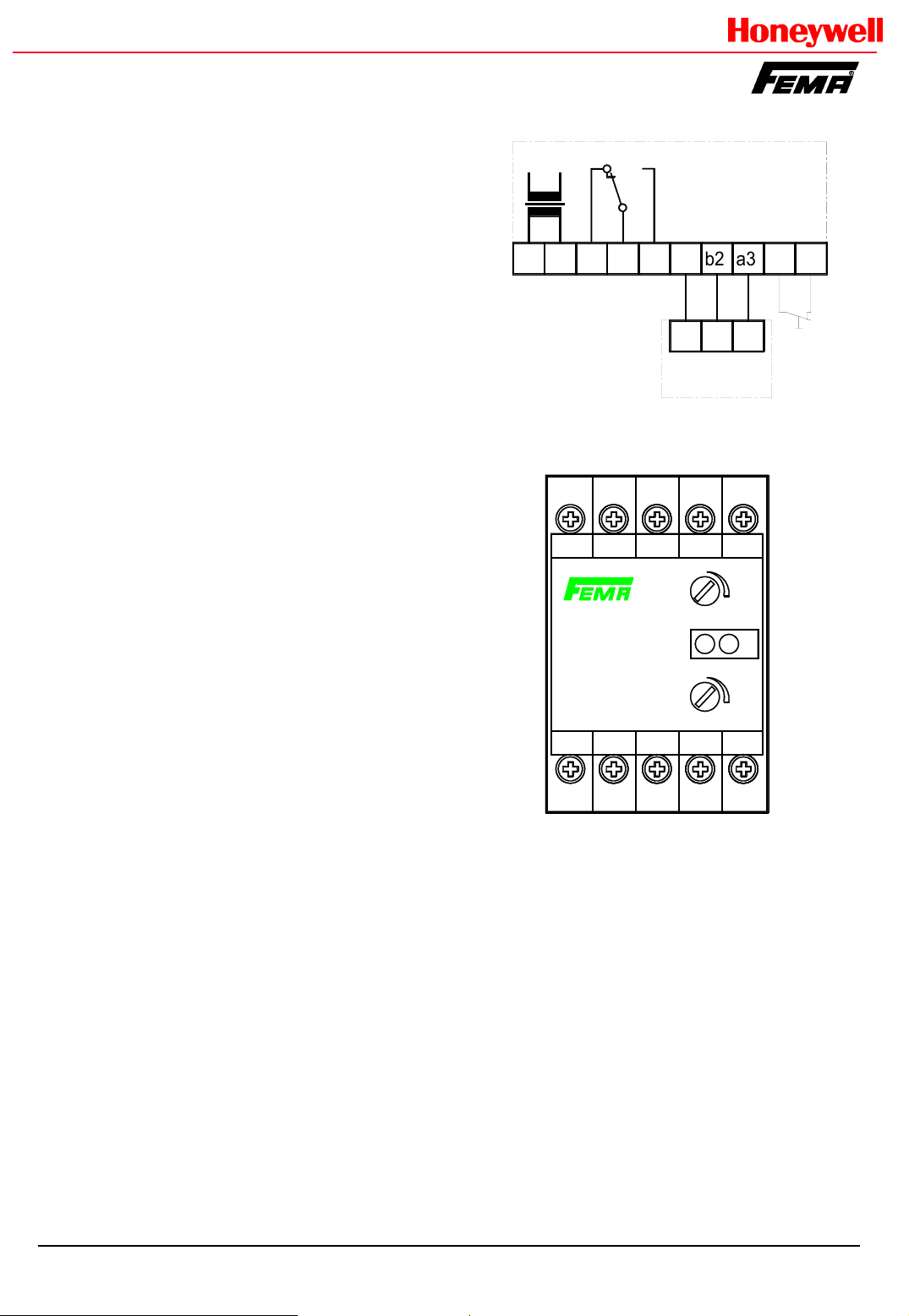
Elektrischer Anschluß
Anschlußplan
Die Klemmen des Sensors sind mit den
Klemmen am Auswertegerät zu verbinden
(siehe Anschlußplan). Vertauschung führt zu
Fehlfunktionen.
Max. Kabellänge: 100 m (3 X 1,5 qmm)
Wird die Fühlerleitung gemeinsam mit
anderen stromführenden Leitungen verlegt,
ist die Fühlerleitung abzuschirmen.
Die einschlägigen Vorschriften für die
Installation elektrischer Anlagen sind zu
beachten.
Inbetriebnahme
1. Strömungserzeuger einschalten
2. Trimmer „Empfindlichkeit „ auf minimale
Empfindlichkeit einstellen (Linksanschlag).
3. Netzspannung anlegen. Die grüne LED
leuchtet. Das Gerät ist nach 2 sec
betriebsbereit.
4. Trimmer „Empfindlichkeit“ langsam in
Richtung Maximum (+) drehen, bis die
gelbe LED leuchtet und das
Ausgangsrelais anzieht. Um stabile
Schaltverhältnisse zu erreichen, etwas
über den Schaltpunkt hinausdrehen.
5. Zur Überprüfung Strömungserzeugung
abschalten oder reduzieren. Die gelbe
LED erlischt und das Ausgangsrelais fällt
ab.
A2
A1
16
15 18
230 V AC
(24 V AC/DC)
a2 = braun
b2 = schwarz
a3 = blau
A1 15 a2
ASL453
230 V AC
Empfindlichkeit
16
18 Z
Zeit
Time
Sensivity
ASL 453
ASL 453/24
a3b2a2
a3b2a2
SENSOR
a3
b2
t
+
1 2
s
+
A2
Z
z
Start
z
Seite 2 von 4
Einschaltüberbrückung
Während des Hochfahrens der Anlage
(noch keine Luftströmung vorhanden),
wird der Ausgangskontakt aktiviert und
der Strömungszustand signalisiert. Die
Zeit für die Einschaltüberbrückung ist von
2-60s einstellbar. Die Anlauf- oder
Einschaltüberbrückung startet beim
Einschalten des Geräts. Bei externer
Beschaltung (Klemmen Z-Z) mit einer
Starttaste (Öffnerkontakt) beginnt die
Anlaufüberbrückung mit dem Betätigen.
Achtung: Wird die Strömungsüberwachung früher als der
Luftstromerzeuger eingeschaltet, kann die
Einschaltüberbrückung bereits abgelaufen
sein. Deshalb Luftstromerzeuger früher
bzw. zusammen mit dem
Luftstromwächter einschalten.
Einstellelemente
s = Empfindlichkeit
(Hohe Empfindlichkeit : niedriger
Schaltpunkt / Strömung)
t = Zeit für Einschaltüberbrückung
(2-60s)
Signallampen
1 = Strömung vorhanden oder
Einschaltüberbrückung aktiv
2= Speisespannung vorhanden
7157 248 / 2
Page 3

Airflow monitoring
Installation and operating instructions
PG7
1 0
3 5 1 5
6 0
1 0
r e d d o t
15mm
1 2 , 5 mm
4 5m m
4.0mm
Fi xin g-Scr ew
3 6 . 0 mm
SLF3 Flange for SLF 3
(
Max. 100°C, PPS, grey, flame
retardant acc. to DIN 4101B1)
Air flow sensor SLF 3 :
The airflow sensor contains a sensor element which is sensitive to mechanical loading and
wich must not be touched with hard and pointed objects. Any cleaning that may be
necessary is possible in water (also with addition of detergents). Let the unit drip off and
dry before renewed start-up.
Technical Data SFL 3
Medium temperatur: - 20 ... + 120°C
Compensation behaviour: fast, approx.0.5 s
Installation depth: 35 mm
Mounting: Directly on the air duct with mounting flange
(belongs to the scope of supply)
Installation position: Vertical or horizontal (observe the
flow direction)
Probe tube: Material brass nickel-plated, diameter=10
mm (important for the hole drilled in the air duct)
Connection cable: Three-conductor; 2,5 m in length
Protective cataegory: IP 65
Assembly
The sensor should be mounted in such a way that
the air flow passes through the lateral opening.
The red coloured marking is intended as an
assembly aid. The length of cable between the sensor
and monitoring appliance should not be more than
100 m. If the sensor cable is laid in a conduit with other
cables (e.g. for monitors or solenoid valves), we
recommend the shielding of the sensor cable. The
sensor must be connected with the evaluation unit
corresponding to the adjacted connection diagram.
Incorrect connection leads to faulty operation.
Evaluation unit ASL 453...
The evaluation unit is intended for
switchgear cabinet installation on
standard rails.
Technical data
Operating voltage: 230 V AC or 24 V
AC/DC according to type (see name
plate)
Power consumption: approx. 3 VA
Ambient temperatur: 0 - 60°C
Switching output: 8 A, max. 250 V AC
Switching hysteresis: approx. 2 % of the
total range
Sensitivity: 0.1 ... 20 m/s for air,
adjustable
Probe breakage protection: On
interruption of the probe cables, the
device is switched off, interruption of low
is signalled.
Type of construction: Standard housing
N45
Seite 3 von 4
FEMA Regelgeräte
Honeywell GmbH ⋅ Postfach 1254 ⋅ 71099 Schönaich
Telefon 07031/637-02 ⋅ Telefax 07031/637-850
7157 248 / 2
Page 4

Electrical connection
The terminals of the sensor must be
connected with the terminals of the
evaluation unit (see connection diagram).
Incorrect connection leads to faulty
operation.
Max. cable length: 100 m (3 x 1.5 mm)
If the probe cable is run together with other
cables use shielded cable.
The relevant regulations for the
installation of electrical systems must be
complied with.
Start-up
1. Switch on flow
2. Turn „sensitivity“ to minimum sensitivity
(leftward)
3. Switch on power supply of ASL... The
green LED switches on. After 2 sec. the
device is ready for operation.
4. Turn „Sensitivity“ towards Maximum (+)
until the yellow LED switches on and the
output relay will switch. For stable
conditions turn slightly beyond switching
point.
5. For verification of correct operation
reduce or switch off flow. The yellow LED
will switch off and the output relay will
switch.
Connection diagram
A2
A1
16
15 18
230 V AC
(24 V AC/DC)
a2 = brown
b2 = black
a3 = blue
A1 15 a2
ASL453
230 V AC
Empfindlichkeit
16
18 Z
Zeit
Time
Sensivity
ASL 453
ASL 453/24
a3b2a2
a3b2a2
SENSOR
a3
b2
t
+
1 2
s
+
Z
A2
z
Start
z
Seite 4 von 4
Switch-on bypass
While the plant is being started up (still no
airflow present), the output contact is
activated and the flow condition singalled.
The time for the switch-on bypass is
adjustable on the potentiometer from 2-60
s. The starting or switch-on bypass starts
when switching the device on. With
external connection (terminals Z-Z) with a
start button (normally closed contact). The
starting bypass starts with actuation of the
button.
Caution: If the flow monitoring is switched
on earlier than the airflow generator, the
switch-on bypass can have already run
down. Therefore switch on the airflow
generator earlier or together with the
airflow monitor.
Setting elements:
s = Sensitivity
(High sensitivity (+) for low switching
point / low flow speed)
t = time for switch-on bypass (2-60s)
Signallamps (LEDs)
1 = Flow present or switch-on bypass
active
2 = Supply voltage present
7157 248 / 2
 Loading...