

Page 1

Intelligent Control Panel
SLC
Wiring Manual
Document 51309
9/17/2014 Rev:
P/N 51309:P4 ECN 14-790
P4
Page 2

Fire Alarm & Emergency Communication System Limitations
While a life safety system may lower insurance rates, it is not a substitute for life and property insurance!
An automatic fire alarm system—typically made up of smoke
detectors, heat detectors, manual pull stations, audible warning
devices, and a fire alarm control panel (FACP) with remote notification capability—can provide early warn ing of a developing fire.
Such a system, however, does not assure protection against
property damage or loss of life resulting from a fire.
An emergency communication system—typically made up of
an automatic fire alarm system (as described above) and a life
safety communication system that may include an autonomous
control unit (ACU), local operating console (LOC), voice communication, and other various interoperable communication met hods—can broadcast a mass notification message. Such a
system, however, does not assure protection against property
damage or loss of life resulting from a fire or life safety event.
The Manufacturer recommends that smoke and/or heat
detectors be located throughout a protected premises following
the recommendations of the current edition of the National Fire
Protection Association S tandard 72 (NFPA 72), manufacturer's
recommendations, State and local codes, and the
recommendations contained in the Guide for Proper Use of
System Smoke Detectors, which is made available at no charge
to all installing dealers. This document can be found at http: //
www.systemsensor.com/appguides/. A study by the Federal
Emergency Management Agency (an agency of the United
States governme nt) indicated that smoke detectors may not go
off in as many as 35% of all fires. While fire alarm systems are
designed to provide early warning against fire, they do not
guarantee warning or protection against fire. A fire alarm system
may not provide timely or adequate warning, or simply may not
function, for a variety of reasons:
Smoke detectors may not sense fire where smoke cannot
reach the detectors such as in chimneys, in or behind walls, on
roofs, or on the other side of closed doors. Smoke detectors
also may not sense a fire on another level or floor of a building.
A second-floor detector, for example, may not sense a first-floor
or basement fire.
Particles of combustion or “smok e ” from a developing fire
may not reach the sensing chambers of smoke detectors
because:
• Barriers such as closed or partially closed doors, walls, chimneys, even wet or humid areas may inhibit particle or smoke
flow.
• Smoke particles may become “cold,” stratify, and not reach
the ceiling or upper walls where detectors are located.
• Smoke particles may be blown aw a y from de tectors by air
outlets, such as air conditioning vent s.
• Smoke particles may be drawn into air returns before reaching the detector.
The amount of “smoke” present may be insufficient to alarm
smoke detectors. Smoke detectors are designe d to ala rm at various levels of smoke density. If such density levels are not created by a developing fire at the location of detectors, the
detectors will not go into alarm.
Smoke detectors, even when working properly, have sensing
limitations. Detectors that have photoelectronic sensing chambers tend to detect smoldering fires better than flaming fires,
which have little visible smoke. Detectors that have ionizing-type
sensing chambers tend to detect fast-flaming fires better than
smoldering fires. Because fires develop in different ways and
are often unpredictable in their growt h, neither type of detector i s
necessarily best and a given type of detector may not provide
adequate warning of a fire.
Smoke detectors cannot be expected to provide adequate warning of fires caused by arson, children playing with matches
(especially in bedrooms), smoking in bed, and violent explosions
(caused by escaping gas, improper storage of flammable materials, etc.).
Heat detectors do not sense particles of combustion and al arm
only when heat on their sensors increases at a predetermined
rate or reaches a predetermined level. Rate-of-rise heat detectors may be subject to reduced sensitivity over time. For this
reason, the rate-of-rise feature of each detector shoul d be tested
at least once per year by a qualified fire protection specialist .
Heat detectors are designed to protect property, not life.
IMPORTANT! Smoke detectors must be installed in the same
room as the control panel and in rooms used by the system for
the connection of alarm transmission wiring, communications,
signaling, and/or power. If detectors are not so located, a developing fire may damage the alarm system, compromising its ability to report a fire.
Audible warning devices such as bells, horns, strobes,
speakers and displays may not alert people if these devices
are located on the other side of closed or partly open doors or
are located on another floor of a building. Any warning device
may fail to alert people with a disability or those who have
recently consumed drugs, alcohol, or medication. Please note
that:
• An emergency communication system may take priority over
a fire alarm system in the event of a life safety emergency.
• Voice messaging systems must be desi gned to meet intelligibility requirements as defined by NFPA, local codes, and
Authorities Having Jurisdiction (AHJ).
• Language and instructional requirements must be clearly disseminated on any local displays.
• Strobes can, under c ertain circumstances, cause seizures in
people with conditions such as epilepsy.
• Studies have sh own that certain people, even when they he ar
a fire alarm signal, do not respond to or comprehend the
meaning of the signal. Audible devices, such as horns and
bells, can have different tonal patterns and frequencies. It is
the property owner's responsibility to conduct fire drills and
other training exercises to make people aware of fire alarm
signals and instruct them on the proper reaction to alarm signals.
• In rare instances, the sounding of a warning device can cause
temporary or permanent hearing loss.
A life safety system will not operate without any electrical
power. If AC power fails, the system will operate from standby
batteries only for a specified time and only if the batteries have
been properly maintained and replaced regularly.
Equipment used in the system may not be technically compatible with the control panel. It is essential to use only equipment
l
is
ted for service with your control panel.
Telephone lines needed to transmit alarm signals from a premises to a central monitoring station may be out of service or temporarily disabled. For added protection against telephone line
failure, backup radio transmission systems are recommended.
The most common cause of life safety system malfunction is
inadequate maintenance. To keep t he entire life safety sys tem in
excellent working order , ongoing mai ntenance is required per the
manufacturer's recommendations, and UL and NFPA standards. At a minimum, the requirements of NFPA 72 shall be followed. Environments with large amounts of dus t, dirt, or hig h air
velocity require more frequent maintenance. A maintenance
agreement should be arranged through the local manufacturer's
representative. Maintenance should be scheduled monthl y or as
required by National and/or local fire codes and should be performed by authorized professional life safety system installers
only . Adequate written reco rds of all inspecti ons should be kept.
Limit-D-1-2013
2 FireLite SLC Wiring Manual — P/N 51309:P4 9/17/2014
Page 3

Installation Precautions
Adherence to the following will aid in problem-free installation with long-term reliability:
WARNING - Several different sources of power can be
connected to the fire alarm control panel. Disconnect all
sources of power before servicing. Control unit and associated equipment may be damaged by removing and/or inserting cards, modules, or interconnecting cables while the unit is
energized. Do not attempt to install, service, or operate this
unit until manuals are read and understood.
CAUTION - System Re-acceptance Test after Software
Changes: To ensure proper system operation, this product
must be tested in accordance with NFPA 72 after any programming operation or change in site-specific software. Reacceptance testing is required after any change, addition or
deletion of system components, or after any modification,
repair or adjustment to system hardware or wiring. All components, circuits, system operations, or sof tware functions known
to be affected by a change must be 100% tested. In addition,
to ensure that other operations are not inadvertently affected,
at least 10% of initiating devices that are not directly affected
by the change, up to a maximum of 50 devices, must also be
tested and proper system operation verified.
This system meets NFPA requirements for operation at 0-49º
C/32-120º F and at a relative humidity 93% ± 2% RH (noncondensing) at 32°C ± 2°C (90°F ± 3°F). However, the useful
life of the system's standby batteries and the electronic components may be adversely affected by extreme temperature
ranges and humidity. Therefore, it is recommended that this
system and its peripherals be installed in an environment with
a normal room temperature of 15-27º C/60-80º F.
Verify that wire sizes are adequate for all initia ting and indicating device loops. Most devices cannot tol erate more than a
10% I.R. drop from the specified device voltage.
Like all solid state electronic devices, this system may
operate erratically or can be damaged when subject ed to li ght ning induced transients. Although no system is completely
immune from lightning transients and interf erence, proper
grounding will reduce susceptibility. Overhead or outside aerial
wiring is not recommended, due to an increased susceptibility
to nearby lightning strikes. Consult with the Technical Services Department if any problems are anticipated or encountered.
Disconnect AC power and batteries prior to removing or
inserting circuit boards. Failure to do so can damage circuits.
Remove all electronic assemblies prior to any drilling, filing,
reaming, or punching of the enclosure. When possible, make
all cable entries from the sides or rear. Before making modifications, verify that they will not interfere with battery, transformer, or printed circuit board location.
Do not tighten screw terminals more than 9 in-lbs. Overtightening may damage threads, resulting in reduced terminal
contact pressure and difficulty wit h screw terminal removal.
This system contains static-sensitive components.
Always ground yourself with a proper wrist strap before handling any circuits so that static charges are removed from the
body . Use static suppressive packaging to protect electronic
assemblies removed from the unit.
Follow the instructions in the inst al lati on, ope rati ng, and programming manuals. These instructions must be followed to
avoid damage to the control panel and a ssociated equipment.
FACP operation and rel iability depend upon proper inst allat ion.
Precau-D1-9-2005
FCC Warning
WARNING: This equipment generates, uses, and can
radiate radio frequency energy and if not installed and
used in accordance with the instruction manual may
cause interference to radio communications. It has been
tested and found to comply with the limits for class A
computing devices pursuant to Subpart B of Part 15 of
FCC Rules, which is designed to provide reasonable
protection against such interference when devices are
operated in a commercial environment. Operation of this
equipment in a residential area is likely to cause interference, in which case the user will be required to correct
the interference at his or her own expense.
Canadian Requirements
This digital apparatus does not exce ed the Class A limit s
for radiation noise emissions from digital apparatus set
out in the Radio Interference Regulations of the Canadian Department of Communications.
Le present appareil numerique n'emet pas de bruit s radi oelectriques depassant les limites applic ables aux appareils numeriques de la classe A prescrites dans le
Reglement sur le brouillage radioelectrique edict e p ar l e
ministere des Communications du Canada.
LiteSpeed™ is a trademark; and FireLite® Alarms is a registered trademark of Honeywell International Inc. Microsoft® and Windows® are registered
trademarks of the Microsoft Corporation.
©2014 by Honeywell International Inc. All rights reserved. Unauth orized use of this document is strictly prohibited.
FireLite SLC Wiring Manual — P/N 51309:P4 9/17/2014 3
Page 4

Software Downloads
In order to supply the latest features and functionality in fire alarm and life safety technology to our customers, we make
frequent upgrades to the embedded software in our products. To ensure that you are installing and programming the latest
features, we strongly recommend that you download the most current version of software for each product prior to
commissioning any system. Contact Technical Support with any questions about software and the appropriate version for a
specific application.
Documentation Feedback
Your feedback helps us keep our documentation up-to-date and accurate. If you have any comments or suggestions about our
online Help or printed manuals, you can email us.
Please include the following information:
•Product name and version number (if applicable)
•Printed manual or online Help
•Topic Title (for online Help)
•Page number (for printed manual)
•Brief description of content you think should be improved or corrected
•Your suggestion for how to correct/improve documentation
Send email messages to:
Please note this email address is for documentation feedback only. If you have any technical issues, please contact Technical
Services.
4 FireLite SLC Wiring Manual — P/N 51309:P4 9/17/2014
Page 5

Table of Contents
Section 1: Introduction.............................................................................................................8
1.1: Scope..............................................................................................................................................................8
1.1.1: Reference Documentation ...................................................................................................................9
1.2: Overview......................................................................................................................................................10
1.3: Polling Protocols .........................................................................................................................................10
1.3.1: Available Protocols............................................................................................................................10
1.3.2: Protocol Use ......................................................................................................................................10
1.4: Devices ........................................................................................................................................................11
1.4.1: Isolator Modules................................................................................................................................11
1.4.2: Monitor Modules...............................................................................................................................11
1.4.3: Control Modules................................................................................................................................11
1.4.4: Relay Modules...................................................................................................................................11
1.4.5: Multiple Input/Output Modules.........................................................................................................11
1.4.6: Intelligent Detectors ..........................................................................................................................11
1.4.7: Manual Pull Station...........................................................................................................................12
1.4.8: Wireless Gateway..............................................................................................................................12
1.4.9: 300 Series Addressable Devices........................................................................................................13
1.5: SLC Capacity...............................................................................................................................................13
1.6: SLC Performance.........................................................................................................................................13
1.7: Surge Suppression........................................................................................................................................13
1.8: LED Operation.............................................................................................................................................13
Section 2: Wiring Requirements............................................................................................14
2.1: Wire Sizing..................................................................................................................................................14
2.1.1: CLIP (Classic Loop Interface Protocol) Mode..................................................................................14
2.1.2: LiteSpeed Mode.................................................................................................................................14
2.2: Measuring Resistance & Length..................................................................................................................15
2.2.1: Two-Wire SLC - Style 4 (Class B)....................................................................................................15
2.2.2: Four-Wire SLC Style 6 & 7 (Class A) ..............................................................................................16
2.3: Shield Wire Termination...................................................... ........................................................................17
2.4: Control Panel Terminal Blocks....................................................................................................................18
2.4.1: MS-9200............................................................................................................................................18
2.4.2: MS-9600, MS-9600LS, & MS-9600UDLS.......................................................................................18
2.4.3: MS-9200UDLS (Software Version 3.0)............................................................................................19
2.4.4: MS-9200UD & MS-9200UDLS (Versions 1 and 2).........................................................................19
2.4.5: MS-9050UD ......................................................................................................................................20
Section 3: SLC Circuits without Isolators ............................................................................21
3.1: Overview......................................................................................................................................................21
3.2: NFPA Style 4 SLC.......................................................................................................................................21
3.3: NFPA Style 6 SLC.......................................................................................................................................22
Section 4: SLC Circuits with Isolators..................................................................................23
4.1: Fault Isolator Devices..................................................................................................................................23
4.1.1: Isolating an SLC Branch....................................................................................................................23
4.1.2: Wiring an Isolator Module ................................................................................................................24
4.2: NFPA Style 4 SLC Using Isolator Modules ................................................................................................25
4.3: NFPA Style 6 SLC Using Isolator Modules ................................................................................................27
4.4: NFPA Style 7 SLC Using Isolator Modules ................................................................................................28
Section 5: Monitor Modules...................................................................................................29
5.1: Descriptions.................................................................................................................................................29
5.1.1: Addressable Monitor Modules ..........................................................................................................29
5.1.2: Zone Interface Modules.....................................................................................................................31
5.1.3: Dual Monitor Module........................................................................................................................33
FireLite SLC Wiring Manual — P/N 51309:P4 9/17/2014 5
Page 6

Table of Contents
5.1.4: Mini Monitor Module........................................................................................................................33
5.2: Installation....................................................................................................................................................33
5.2.1: Setting an SLC address for a Single Point Module ...........................................................................34
5.2.2: Setting an SLC address for a Multi-Point Module ............................................................................35
5.3: MMF-300 Wiring Diagrams........................................................................................................................36
5.3.1: Wiring a NFPA Style B IDC with an MMF-300...............................................................................36
5.3.2: Wiring a NFPA Style D IDC with an MMF-300 ..............................................................................37
5.3.3: MMF-300 Wiring for Emergency Alarm System Applications........................................................38
5.4: MMF-300-10 Wiring Diagrams...................................................................................................................39
5.4.1: Wiring a NFPA Style B IDC with an MMF-300-10 .........................................................................39
5.4.2: Wiring a NFPA Style D IDC with an MMF-300-10.........................................................................40
5.5: MDF-300 Wiring Diagrams.........................................................................................................................41
5.5.1: Wiring a NFPA Style B IDC with an MDF-300 ...............................................................................41
5.6: MMF-302 Wiring Diagrams........................................................................................................................42
5.6.1: Wiring a NFPA Style B IDC with an MMF-302...............................................................................42
5.6.2: Wiring a NFPA Style D IDC with an MMF-302 ..............................................................................43
5.7: MMF-302-6 Wiring Diagrams.....................................................................................................................44
5.7.1: Wiring a NFPA Style B IDC with an MMF-302-6 ...........................................................................44
5.7.2: Wiring a NFPA Style D IDC with an MMF-302-6 ...........................................................................45
Section 6: Control Modules ...................................................................................................46
6.1: Description...................................................................................................................................................46
6.2: CMF-300 Installation...................................................................................................................................46
6.2.1: Setting an SLC address for a CMF-300 Module ...............................................................................46
6.2.2: Wiring a Notification Appliance Circuit (NAC) with a CMF-300....................................................46
6.3: Wiring a CMF-300 Module .........................................................................................................................47
6.3.1: Wiring a Style Y NAC (Two-Wire) with Addressable Control Modules .........................................47
6.3.2: Wiring a Style Z NAC (Four-Wire) with Addressable Control Modules .........................................48
6.4: CMF-300-6 Installation ...............................................................................................................................48
6.4.1: Cabinet Installation............................................................................................................................48
6.4.2: Setting an SLC address for an CMF-300-6 Module..........................................................................48
6.4.3: Setting NACs as Style Y or Style Z...................................................................................................49
6.4.4: Disabling Unused Module Addresses................................................................................................49
6.4.5: Short Circuit Protection.....................................................................................................................49
6.4.6: Features Not Supported .....................................................................................................................50
6.4.7: Circuit Board Information .................................................................................................................50
6.5: Wiring a CMF-300-6 Module......................................................................................................................51
6.5.1: Wiring a Style Y NAC (Two-Wire) .................................................................................................51
6.5.2: Wiring a Style Z NAC (Four-Wire)...................................................................................................52
Section 7: Relay Modules ......................................................................................................53
7.1: Description...................................................................................................................................................53
7.2: CRF-300 Installation & Wiring...................................................................................................................53
7.2.1: Setting an SLC address for a CRF-300 Module ................................................................................53
7.2.2: Wiring a CRF-300 Module (Form-C Relay) ....................................................................................53
7.3: CRF-300-6 Circuit Board Information ........................................................................................................54
7.4: CRF-300-6 Installation & Wiring................................................................................................................54
7.4.1: Cabinet Installation............................................................................................................................54
7.4.2: Setting an SLC address for a CRF-300-6 Module.............................................................................55
7.4.3: Disabling Unused Module Addresses................................................................................................55
7.4.4: Wiring a CRF-300-6 Module (Form-C Relay)..................................................................................55
Section 8: Multiple Input/Output Modules............................................................................57
8.1: Description...................................................................................................................................................57
8.2: CDRM-300 Installation & Wiring...............................................................................................................57
8.2.1: Setting an SLC address for a CDRM-300 Module............................................................................57
8.2.2: Wiring a CDRM-300 Module (Form-C Relay)................................................................................58
6 FireLite SLC Wiring Manual — P/N 51309:P4 9/17/2014
Page 7

Table of Contents
Section 9: Intelligent Detector Bases and Wireless Gateway.............................................59
9.1: Description...................................................................................................................................................59
9.2: Setting the Detector Address .......................................................................................................................59
9.3: Wiring a Detector Base................................................................................................................................60
9.4: Wiring an Isolator Base ...............................................................................................................................61
9.5: Wiring a Relay Base....................................................................................................................................61
9.6: Wiring a Sounder Base................................................................................................................................62
9.7: Wiring the W-GATE....................................................................................................................................62
9.7.1: SLC Connections...............................................................................................................................62
9.7.2: W-GATE Powered by the SLC....................................................... ..................................................63
9.7.3: W-GATE Powered by a Regulated, External +24VDC Power Source.............................................64
Section 10: Addressable Beam Detectors............................................................................65
10.1: Description.................................................................................... .............................................................65
10.2: Installation and Wiring..............................................................................................................................65
10.2.1: Setting an SLC Address for a Beam Detector.................................................................................65
10.2.2: Wiring a Beam Detector..................................................................................................................66
Section 11: Addressable Manual Pull Station......................................................................67
11.1: Description.................................................................................................................................................67
11.2: Installation..................................................................................................................................................67
11.2.1: Setting an SLC address....................................................................................................................67
11.2.2: Wiring a Manual Pull Station..........................................................................................................67
Appendix A: Power Considerations......................................................................................68
A.1: Supplying Power to 24 VDC Detectors and NACs ....................................................................................68
A.1.1: Resistance and Size...........................................................................................................................68
A.2: Supervising 24 VDC Power........................................................................................................................69
Appendix B: Surge Suppression ...........................................................................................71
B.1: Introduction.................................................................................................................................................71
B.2: Installation...................................................................................................................................................71
B.2.1: Wiring Diagram for MS-9200 ..........................................................................................................72
B.2.2: Wiring Diagram for MS-9600, MS-9600LS, MS-9600UDLS, MS-9200UD, MS-9200UDLS, and
MS-9050UD ................................................................................................................................................73
Appendix C: Terminal Conversion Charts for New & Legacy Devices..............................74
C.1: CRF-300......................................................................................................................................................74
C.2: CMF-300 and MMF-302 ............................................................................................................................75
C.3: MMF-300....................................................................................................................................................76
C.4: MDF-300.....................................................................................................................................................77
Appendix D: Intelligent Detector Base Layouts for Legacy Devices.................................78
D.1: B350LP or B501 Detector Base..................................................................................................................78
D.2: B224BI Isolator Base.................................................................................................................................79
D.3: B224RB Relay Base ...................................................................................................................................79
D.4: B501BH(-2) and B501BHT(-2) Sounder Bases............................................................................... ..........80
Appendix E: Canadian Versions of SLC Devices ................................................................82
Index.........................................................................................................................................84
FireLite SLC Wiring Manual — P/N 51309:P4 9/17/2014 7
Page 8
1.1 Scope
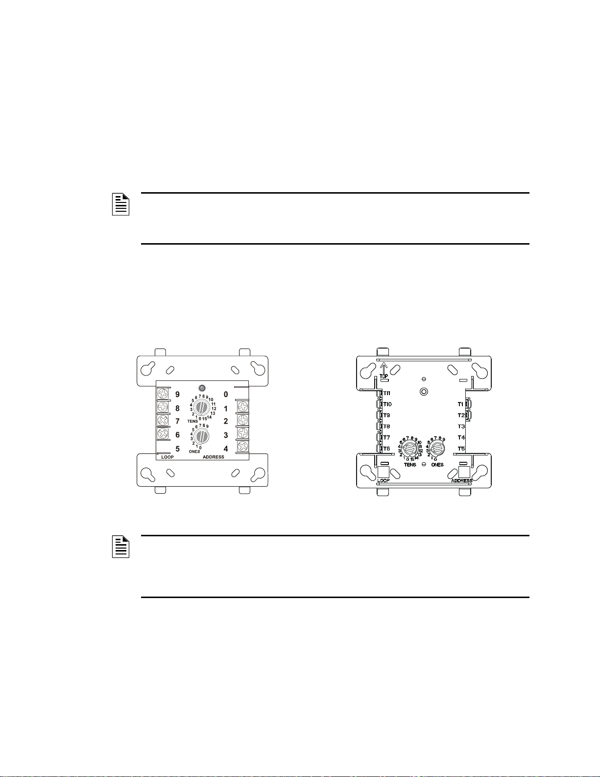
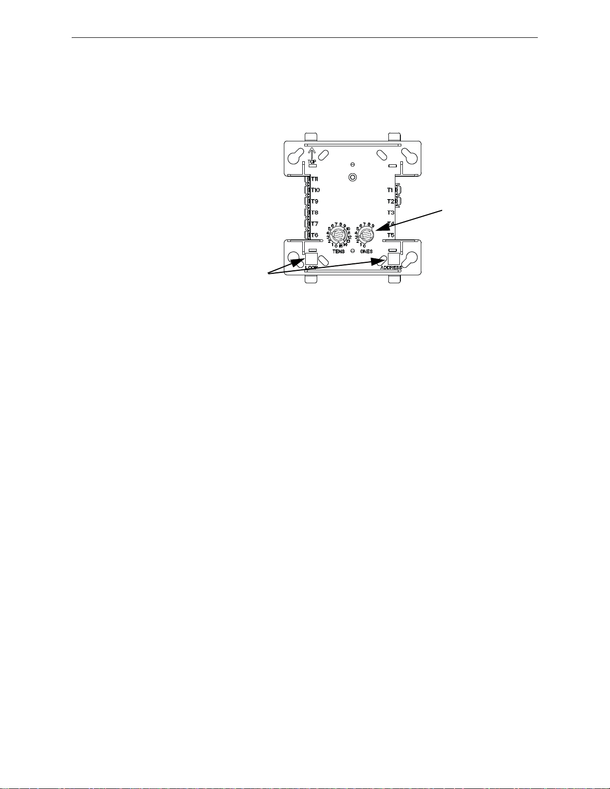
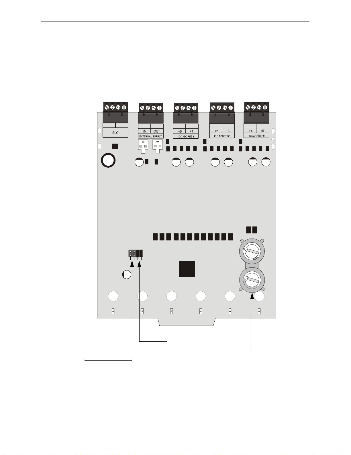
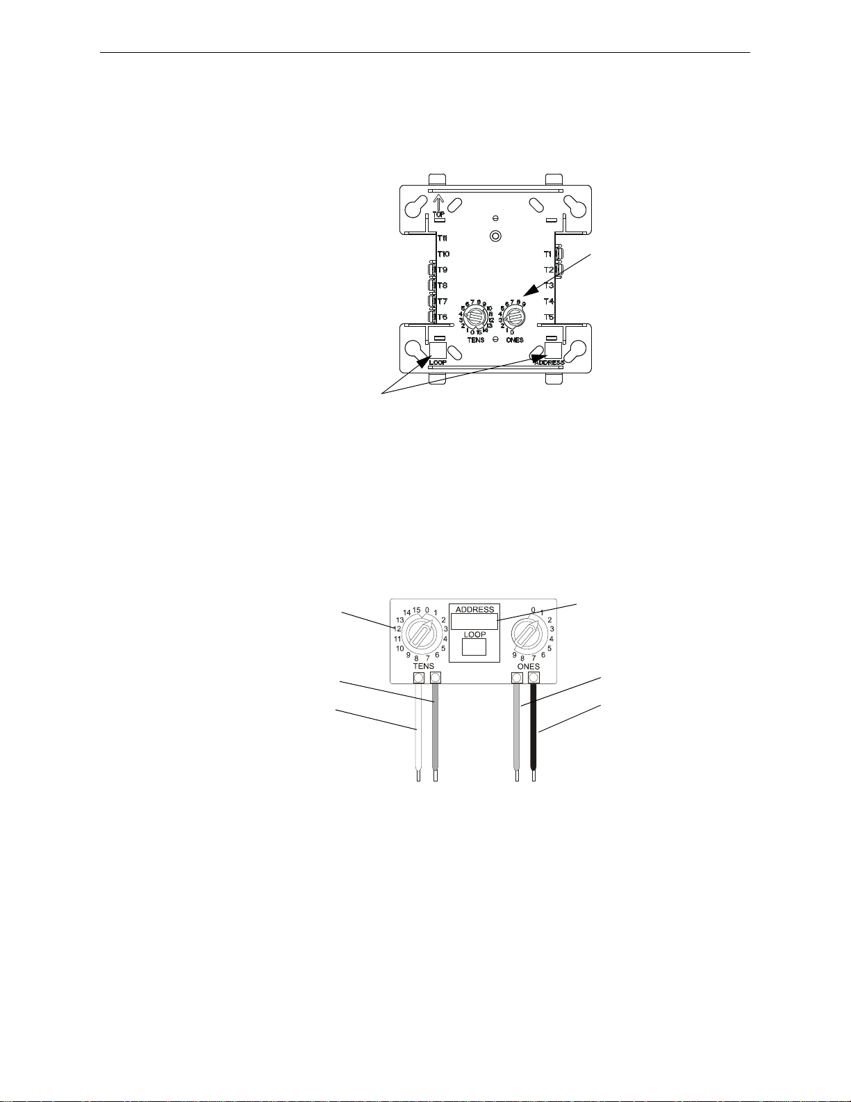
CMF-300
Legacy Version Module
(Vertical Rotary Dial)
CMF-300
Newer Version Module
(Horizontal Rotary Dial)
Section 1: Introduction
This document describes the operation, installation and wiring of various Signaling Line Circuit
(SLC) devices when used with the Fire-Lite MS-9200/MS-9200E, MS-9600/MS-9600E, MS9600LS/MS-9600LSC/MS-9600LSE, MS-9600UDLS/MS-9600UDLSE, MS-9200UD/MS9200UDE, MS-9200UDLS/MS-9200UDLSE/MS-9200UDLSC, and MS-9050UD/MS9050UDC/MS-9050UDE control panels. It also provides basic information that applies to Fire•Lite
SLC loops in general, such as the branch resistance measurements.
NOTE: Any reference in this manual to the MS-9200, MS-9200UD, MS-9200UDLS, MS-9600,
MS-9600LS, MS-9600UDLS, or MS-9050UD includes the MS-9200E, MS-9200UDE,
MS-9200UDLSE, MS-9200UDLSC, MS-9600E, MS-9600LSE, MS-9600LSC, MS-9600UDLSE,
MS-9050UDC, or MS-9050UDE respectively unless otherwise specified.
Additional information about the specific control panel and the modules and detectors referenced in
this document can be found in the respective installation manual as listed in Table 1.1, “Reference
Documentation”.
Currently, there are two styles of modules available, legacy version and newer version. The obvious
difference between the two styles is the orientation of the rotary dials. Refer to the diagram below
for an example of each.
NOTE: Only the MMF-300, MMF-302, CRF-300, CMF-300, and MDF-300 modules are available
as newer type modules. Both the legacy and newer versions share the same part numbers. The
newer version modules will be phased in, replacing the legacy version. This manual contains
information and wiring diagrams for the newer version of the modules. Refer to “Terminal
Conversion Charts for New & Legacy Devices” on page 74 for additional information.
8 FireLite SLC Wiring Manual — P/N 51309:P4 9/17/2014
Page 9

Scope Introduction
Currently, there are two styles of detector bases available, legacy version and newer version. The
obvious difference between the two styles is the orientation of the screw terminals. Refer to
Section 9 and Appendix D for an illustration of each.
NOTE: Only the B501 Detector Base, B210LP Detector Base (replacement base for B350LP),
B224RB Relay Base, and B224BI Isolator Base are available as newer type bases. Both the
legacy and newer versions share the same part numbers. The newer version bases will be
phased in, replacing the legacy version. This manual contains information and wiring diagrams for
the newer version of the bases. Refer to “Intelligent Detector Base Layouts for Legacy Devices”
on page 78 for additional information.
1.1.1 Reference Documentation
The table below accommodates a list of document sources containing additional information
regarding the devices used on a Signaling Line Circuit:
For information on... Refer to... Part Number
MS-9200/MS-9200E Instruction Manual 51003
MS-9600/MS-9600E Instruction Manual 51335
MS-9200UD/MS-9200UDE Instruction Manual 51906
MS-9200UDLS/MS-9200UDLSE/MS-9200UDLSC Instruction Manual 52750
MS-9600LS/MS-9600LS(C/E) & MS-9600UDLS/MS9600UDLSE Instruction Manual 52646
MS-9050UD/MS-9050UDC/MS-9050UDE Instruction Manual 52413
Compatible Devices Device Compatibility Document 15384
Wireless Sensor Network Instruction Manual LS10036-000FL-E
BG-12LX Pull Station Installation Instructions I56-3655
MMF-300 Monitor Module Installation Instructions I56-1191 / I56-3653
MMF-300-10 Monitor Module Installation Instructions I56-1873
MMF-301 Mini Monitor Module Installation Instructions I56-1193 / I56-3654
MMF-302 Monitor Module Installation Instructions I56-1192 / I56-3652
MMF-302-6 Interface Module Installation Instructions I56-1900
MDF-300 Dual Monitor Module Installation Instructions I56-0013 / I56-3665
CMF-300 Control Module Installation Instructions I56-1189 / I56-3650
CMF-300-6 Control Module Installation Instructions I56-1874
CRF-300 Relay Module Installation Instructions I56-1190 / I56-3651
CRF-300-6 Relay Module Installation Instructions I56-1875
CDRM-300 Multiple Input/Output Module Installation Instructions I56-3726
I300 Isolator Module Installation Instructions I56-1381
ISO-6 Isolator Module Installation Instructions I56-4096
AD350 Multicriteria Detector Installation Instructions F300-17-00
AD355 Multicriteria Detector Installation Instructions I56-3660
SD350 & SD350T Photo Detector Installation Instructions I56-0035
SD355 & SD355T Photo Detector Installation Instructions I56-3660
CP350 Ionization Detector Installation Instructions I56-0036
CP355 Ionization Detector Installation Instructions I56-3656
H350 Heat Detector Installation Instructions I56-0038
H350R Heat Detector w/ROR Installation Instructions I56-0037
H355 Heat Detector (135
H355R Heat Detector w/ROR Installation Instructions I56-3657
H355HT Heat Detector (190
D350P Duct Detector Installation Instructions F300-10-00
D350PL(A) Duct Detector - low flow Installation Instructions I56-1975
°) Installation Instructions I56-3657
°) Installation Instructions I56-3657
Table 1.1 Reference Documentation
FireLite SLC Wiring Manual — P/N 51309:P4 9/17/2014 9
Page 10

Introduction Overview
For information on... Refer to... Part Number
D350RP Duct Detector w/Relay Installation Instructions I56-0047
D350RPL(A) Duct Detector w/Relay - low flow Installation Instructions I56-1974
D355PL Duct Detector - low flow Installation Instructions I56-3255
BEAM355(S) Addressable Beam Detector Installation Instructions I56-2425
B210LP Plug-in Detector Base Installation Instructions I56-3739
B501 Detector Base Installation Instructions I56-0357 / I56-3738
B501BH Sounder Detector Base Installation Instructions I56-0491
B501BH-2 Sounder Detector Base Installation Instructions I56-2813
B501BHT Temporal Sounder Detector Base Installation Instructions I56-1367
B501BHT-2 Temporal Sounder Detector Base Installation Instructions I56-2819
B200SR Sounder Detector Base Installation Instructions I56-3387
B200SR-LF Low Frequency Sounder Detector Base Installation Instructions I56-4152
B224RB Relay Detector Base Installation Instructions I56-2815 / I56-3737
B224BI Isolator Detector Base Installation Instructions I56-0725 / I56-3736
Table 1.1 Reference Documentation
1.2 Overview
Communication between the control panel and intelligent addressable monitor and control devices
takes place through a Signaling Line Circuit (SLC), which can be wired to meet the requirements of
NFPA Style 4, Style 6, or Style 7.
At least one secondary surge protector must be used with each SLC wiring pair whenever SLC
wiring runs outside the building. For detailed information refer to “Surge Suppression” on page 71.
1.3 Polling Protocols
The MS-9200UDLS, MS-9600LS, and MS-9600UDLS support LiteSpeed protocol or Classic
Loop Interface Protocol (CLIP). The MS-9200/E, MS-9600/E, MS-9200UD/E, and MS-9050UD
support Classic Loop Interface Protocol (CLIP) only.
1.3.1 Available Protocols
LiteSpeed is a communication protocol that greatly enhances the speed of communication between
analog intelligent devices. Only the MS-9200UDLS, MS-9600LS, and MS-9600UDLS are capable
of operating in LiteSpeed mode. This is the default mode of operation for these FACPs.
CLIP (Classic Loop Interface Protocol) polls devices in sequential order. All Fire-LiteFireWarden
addressable fire alarm control panels can operate in CLIP mode. This is the default mode of
operation for all other FACPs.
1.3.2 Protocol Use
Use one of the following options with LiteSpeed/CLIP mode:
1. Program all modules and detectors on an FACP as LiteSpeed.
2. Program all modules and detectors on an FACP as CLIP.
NOTE: FACPs with more than one SLC loop must be programmed for only LiteSpeed or CLIP
mode of operation. Communication protocols cannot be split between SLC loops.
When switching between polling protocols, the loop circuit must be powered down for at least 30
seconds to reset the devices.
10 FireLite SLC Wiring Manual — P/N 51309:P4 9/17/2014
Page 11

Devices Introduction
1.4 Devices
1.4.1 Isolator Modules
Isolator Modules permit a zone of detectors and modules to be fault isolated from the remainder of
the SLC loop, allowing critical components to function in the event of a circuit fault. Isolator
modules are required to meet the requirements of an NFPA Style 7 circuit.
I300 - Single fault isolator module
ISO-6 - Six fault isolator module
1.4.2 Monitor Modules
Addressable modules that allow the control panel to monitor entire circuits of conventional alarm
initiating devices, such as manual pull stations, smoke detectors, heat detectors, waterflow and
supervisory devices.
MMF-300 - Monitors a Style B (Class B) or Style D (Class A) circuit of dry-contact input devises.
MMF-300-10 - Monitors ten (10) Style B (Class B) or five (5) Style D (Class A) normally open
contact device circuits.
MMF-301 - Same as the MMF-300 except offered in a smaller package for mounting with Style B
wired devices. This module does not have an LED.
MMF-302 - Monitors a single IDC of two-wire smoke detectors.
MMF-302-6 - An addressable module that provides an interface between the control panel and six
(6) Style B (Class B) or three (3) Style D (Class A) IDCs of two-wire smoke detectors.
MDF-300 - Similar to MMF-300, but provides for two independent Style B IDCs.
1.4.3 Control Modules
Through the CMF-300 addressable control module, the control panel can selectively activate a
Notification Appliance Circuit (NAC).
CMF-300-6 - Similar in operation to the CMF-300, except it can activate six (6) Style Y (Class B)
or three (3) Style Z (Class A) NACs.
1.4.4 Relay Modules
The CRF-300 addressable relay module provides the control panel with a dry-contact output for
activating a variety of auxiliary devices.
CRF-300-6 - Similar in operation to the CRF-300, except it provides six (6) Form-C relays.
1.4.5 Multiple Input/Output Modules
The CDRM-300 addressable multiple input/output module monitors two (2) Style B input devices
and provides two (2) independent Form-C relay contacts.
1.4.6 Intelligent Detectors
AD350 - A multicriteria smoke sensor that combines a photoelectric sensing chamber and 135°F
(57.2°C) fixed temperature heat detection. The sensor uses addressable communication to transmit
smoke density and other information to the control panel. It adjusts its detection parameters and
alarm threshold depending on the ambient conditions it samples in its environment.
AD355 - A multicriteria smoke sensor that combines a photoelectric sensing chamber and 135°F
(57.2°C) fixed temperature heat detection. The sensor uses addressable communication to transmit
smoke density and other information to the control panel. It adjusts its detection parameters and
alarm threshold depending on the ambient conditions it samples in its environment.
FireLite SLC Wiring Manual — P/N 51309:P4 9/17/2014 11
Page 12

Introduction Devices
CP350 - An addressable ionization smoke detector which measures the level of combustion
products in its chamber using the ‘ionization principle’.
CP355 - An addressable ionization smoke detector which measures the level of combustion
products in its chamber using the ‘ionization principle’.
D350P - An addressable photoelectric duct detector. The D350RP includes an alarm relay. Air
velocity rating is 500 to 4,000 feet per minute.
D350PL -An addressable low flow photoelectric duct detector (D350PLA for Canada). The
D350RPL includes an alarm relay (D350RPLA for Canada). Low Flow refers to the air velocity
rating of 100 to 4,000 feet per minute (0.5 to 20.32 m/sec).
D355PL - An addressable non-relay photoelectric low flow smoke detector. Low Flow refers to
the air velocity rating of 100 to 4,000 feet per minute (0.5 to 20.32 m/sec).
1
- An addressable detector using a thermistor sensing circuit for fast response. H350R
H350
incorporates a thermal rate of rise of 15°F (9.4°C)/minute.
1
- An addressable 135° fixed temperature heat detector using a thermistor sensing circuit for
H355
fast response. H355R incorporates a thermal rate of rise of 15° F (9.4° C)/minute.
1
H355HT
- An addressable 190° fixed temperature heat detector using a thermistor sensing circuit
for fast response.
SD350 - An addressable photoelectric smoke detector which provides smoke sensing utilizing
optical sense technology. The SD350T includes a 135° F fixed thermal sensor.
SD355 - An addressable photoelectric smoke detector which provides smoke sensing utilizing
optical sense technology. The SD355T includes a 135° F fixed thermal sensor. The SD355R is a
low profile, intelligent, photoelectric sensor that is remote test capable.
BEAM355 - An addressable long range projected beam smoke detector designed to provide open
area protection. The BEAM355S has an integral sensitivity test feature that consists of a test filter
attached to a servomotor inside the detector optics.
DNR(W) - Innovair Flex, intelligent, non-relay, low flow, photoelectric duct detector housing.
This requires the SD355R photoelectric smoke detector. Accomodates the installation of the CRF300 relay module. The DNRW is a watertight housing.
1.4.7 Manual Pull Station
The BG-12LX is a dual-action pull station that, when activated, provides an addressable
identification and its location to the control panel. An addressable monitor module is mount ed
inside the pull station to facilitate servicing and replacement.
1.4.8 Wireless Gateway
W-GATE: The Wireless Gateway acts as a bridge between a group of wireless fire devices and a
LiteSpeed SLC loop on the MS-9200UDLS. It is powered by the SLC loop or by a regulated,
external 24VDC UL listed power supply. Available wireless devices include a photo detector, a
photo/heat detector, a fixed-temperature heat detector, a rate-of-rise heat detector, and a monitor
module. For details about wireless devices, system setup, and operation, see the SWIFT™ Smart
Wireless In tegrated Fire Technology Instruction Manual.
NOTE: The W-GATE, as part of the wireless network, has been tested for compliance with the
Federal Communications Commission (FCC) requirements of the United States Government. It
has not been evaluated for use outside the USA. Use of this system outside the USA is subject to
local laws and rules to which this product may not conform. It is the sole responsibility of the user
to determine if this product may be legally used outside the USA.
1. Addressable Heat Detectors are not compatible with the MS-9200(E).
12 FireLite SLC Wiring Manual — P/N 51309:P4 9/17/2014
Page 13

SLC Capacity Introduction
1.4.9 300 Series Addressable Devices
Fire•Lite’s 300 Series of addressable devices are fully compatible with the MS-9200, MS-9200UD,
MS-9200UDLS, MS-9600, MS-9600LS(C/E), MS-9600UDLS/E, and MS-9050UD FACPs. The
devices must be configured for CLIP (Classic Loop Interface Protocol) Mode operation. The
address of 300 series devices cannot be set above 99. Compatible devices include:
• SD300 Photo • M300 Monitor Module
• SD300T Photo w/Thermal • M301 Mini Monitor Module
• CP300 Ionization • M302 2-wire Monitor Module
• BG-10LX Pull Station • C304 Control/Relay Module
1.5 SLC Capacity
The protocol selected for an SLC loop determines the maximum number of devices that can be
handled by the loop. See Section 1.3, “Polling Protocols”, on page 10. Within those limits, the
individual control panel may have additional restrictions. See the specific installation manual for
this information.
1.6 SLC Performance
SLC performance depends on the type of circuit (Style 4, Style 6, or Style 7) and the components
on the circuit.
NOTE: SLC operation meeting Style 7 requirements isolates each device on the SLC from faults
that may occur within other areas of the SLC.
Wiring style requirements are determined by national and local codes. Consult with the Authority
Having Jurisdiction before wiring the SLC. The table below (derived from NFPA 72-1999) lists
the trouble conditions that result when a fault exists on an SLC.
Type of Fault Style 4 Style 6 Style 7
Single Open Trouble Alarm, Trouble Alarm, Trouble
Single Ground Alarm, Trouble (ground) Alarm, Trouble (ground) Alarm, Trouble (ground)
Short Trouble Trouble Alarm, Trouble
Short and open Trouble Trouble Trouble
Short and ground Trouble Trouble Alarm, Trouble
Open and ground Trouble Alarm, Trouble Alarm, Trouble
Communications loss Trouble Trouble Trouble
• Trouble - The control panel will indicate a trouble condition for this type of fault.
• Alarm - The control panel must be able to process an alarm input signal in the presence of this type of fault.
1.7 Surge Suppression
One primary surge protector must be used with each SLC wiring pair whenever SLC wiring runs
outside the building. For detailed information refer to “Surge Suppression” on page 71.
Table 1.2 SLC Performance
1.8 LED Operation
The table below lists the LED operation on the various devices on an SLC.
Device Standby Activated
Monitor Module
Control Module
Detector
FireLite SLC Wiring Manual — P/N 51309:P4 9/17/2014 13
Blinks RED
Blinks GREEN
Blinks RED
Steady RED
Steady GREEN
Steady RED
Table 1.3 LED Operation
Page 14

Section 2: Wiring Requirements
2.1 Wire Sizing
The SLC requires use of a specific wire type, depending on the mode of operation, to ensure proper
2
circuit functioning. Wire size should be no smaller than 18 AWG (0.75 mm
2
AWG (3.25 mm
) wire. The wire size depends on the length of the SLC circuit. It is recommended
) and no larger than 12
that all SLC wiring be twisted-pair to minimize the effects of electrical interference.
2.1.1 CLIP (Classic Loop Interface Protocol) Mode
All addressable FACPs can operate in CLIP (Classic Loop Interface Protocol) mode. It is
recommended that all SLC wiring be twisted-pair and shielded when operating in CLIP mode to reduce
the effects of electrical interference. Use the table below to determine the specific wiring requirements
for the SLC.
Wire Requirements Distance in Feet (meters) Wire Size Wire Type
2
) Belden 9583, Genesis 4410,
Signal 98230, WPW D999
2
) Belden 9581, Genesis 4408,
Signal 98430, WPW D995
2
) Belden 9575, Genesis 4406, &
4606, Signal 98630, WPW
D991
2
) Belden 9574, Genesis 4402 &
4602, Signal 98300, WPW
D975
Twisted-pair, shielded
10,000 feet (3,048 m) 12 AWG (3.1 mm
8,000 feet (2,438 m) 14 AWG (2.0 mm
4,875 feet (1,486 m) 16 AWG (1.3 mm
3,225 feet (983 m) 18 AWG (0.75 mm
MS-9200 = 1,000 feet (305 m)
Untwisted, unshielded
wire, inside conduit or
not in conduit
2.1.2 LiteSpeed Mode
Wire Requirements Distance in Feet (meters) Wire Size Wire Type
Twisted-pair,
unshielded
MS-9600, MS-9600LS(C) &
MS-9600UDLS = 3,000 feet (914 m)
MS-9200UD & MS-9200UDLS = 3,000 feet (914
m)
MS-9050UD = 3,000 feet (914 m)
12 to 18 AWG
Table 2.1 SLC Wiring Requirements in CLIP Mode
The MS-9200UDLS, MS-9600LS, and MS-9600UDLS SLC can be programmed to operate in
LiteSpeed mode for a quicker device response time. While shielded wire is not required, it is
recommended that all SLC wiring be twisted-pair to minimize the effects of electrical interference.
Use the following table to determine the specific wiring requirements for the SLC.
2
10,000 feet (3,048 m) 12 AWG (3.1 mm
8,000 feet (2,438 m) 14 AWG (2.0 mm
4,875 feet (1,486 m) 16 AWG (1.3 mm
3,225 feet (983 m) 18 AWG (0.75 mm
) Belden 5020UL & 6020UL,
Genesis WG-4315 & WG-4515
2
) Belden 5120UL & 6120UL,
Genesis WG-4313 & WG-4513
2
) Belden 5220UL & 6220UL,
Genesis WG-4311 & WG-4511
2
) Belden 5320UL & 6320UL,
Genesis WG-4306 & WG-4506
Table 2.2 SLC Wiring Requirements in LiteSpeed Mode
14 FireLite SLC Wiring Manual — P/N 51309:P4 9/17/2014
Page 15
Measuring Resistance & Length Wiring Requirements
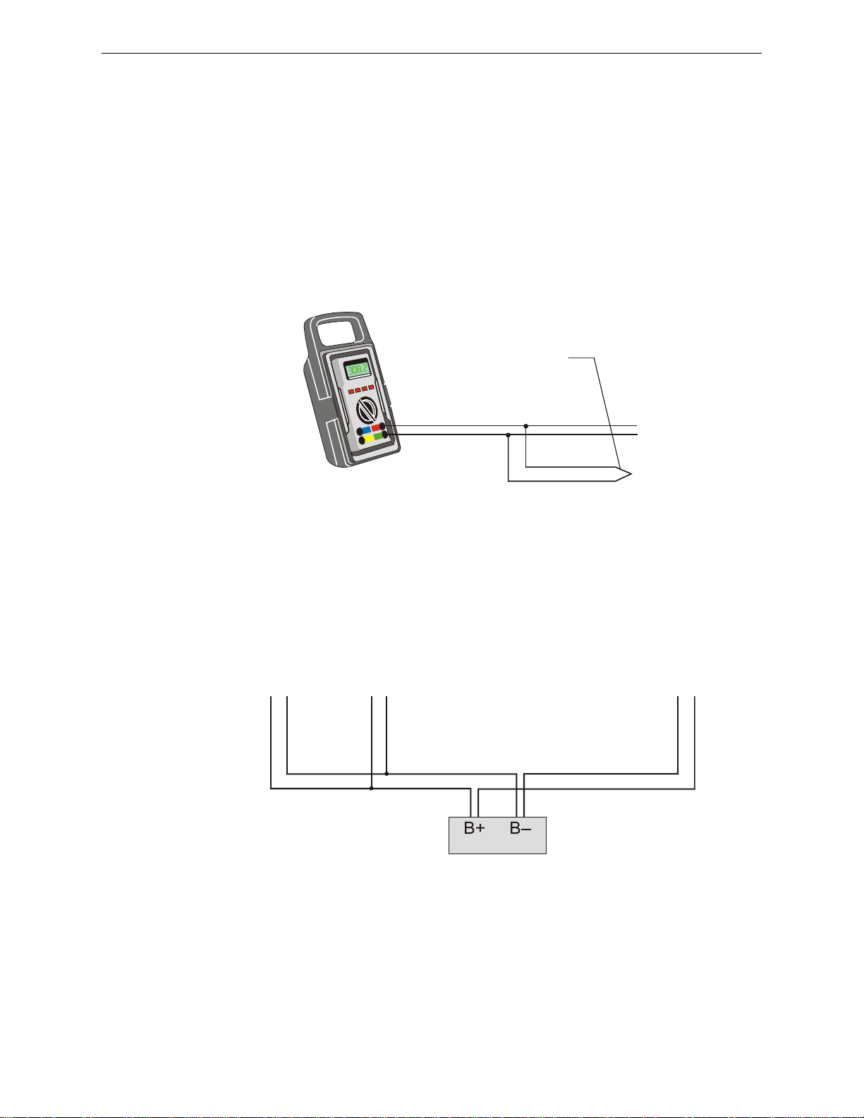
SLC-meas1.wmf
SLC Out
Branch
Short Point
Figure 2.1 Measuring DC Resistance of a Two-Wire SLC
Branch A Branch B
Branch C
SLC-meas2.wmf
SLC Terminal
Block
Figure 2.2 Measuring the Total Wire Length - Two-Wire SLC
2.2 Measuring Resistance & Length
2.2.1 Two-Wire SLC - Style 4 (Class B)
Loop Resistance
T-tapping of the SLC wiring is permitted for 2-wire Style 4 configurations. The total DC resistance
from the control panel to each branch end cannot exceed 40 ohms. Measure DC resistance as
detailed and shown below:
1. With power removed, short the termination point of one branch at a time and measure the DC
resistance from the beginning of the SLC to the end of that particular branch.
2. Repeat this procedure for all remaining branches in the SLC.
Total Wire Length
The total wire length of all combined branches of one SLC cannot exceed the limits set forth in
each system’s instruction manual. Determine the total length in each SLC by summing the wire
lengths of all branches of one SLC.
In the following figure, the total length of the SLC is determined by adding the lengths of Branch A
plus Branch B plus Branch C.
FireLite SLC Wiring Manual — P/N 51309:P4 9/17/2014 15
Page 16
Wiring Requirements Measuring Resistance & Length
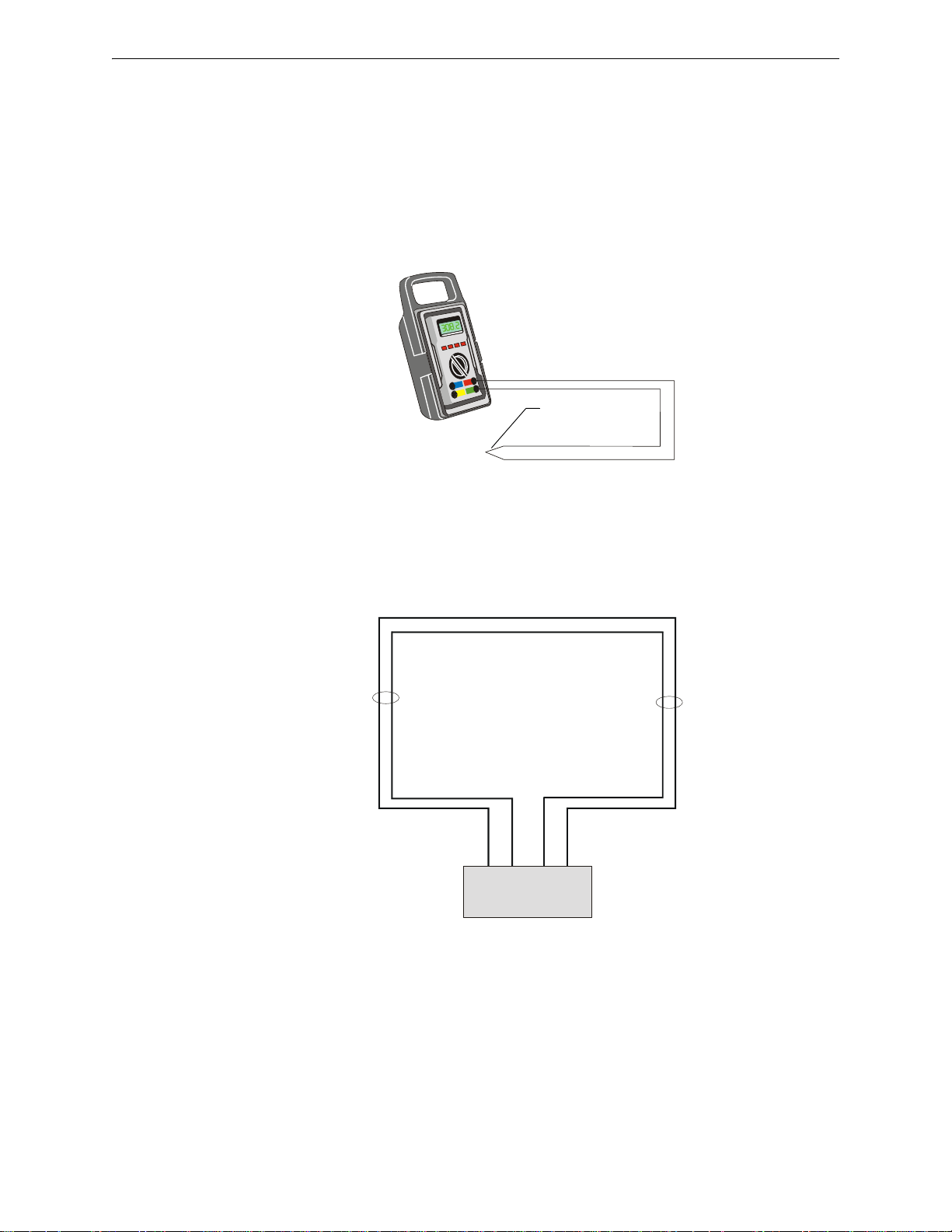
SLC-meas3.wmf
SLC Out
SLC Return
Short Point
Figure 2.3 Measuring DC Resistance of a Four-Wire SLC
B+ B– A– A+
SLC-meas4.wmf
SLC channel B
(output loop)
SLC channel A
(return loop)
SLC Terminal
Block
Figure 2.4 Measuring the Wire Length – Four-Wire SLC
2.2.2 Four-Wire SLC Style 6 & 7 (Class A)
Loop Resistance
The total DC resistance of the SLC pair cannot exceed 40 ohms. Measure DC resistance as detailed
and shown below.
1. Disconnect the SLC channel B (Out) and SLC channel A (Return) at the control panel.
2. Short the two leads of SLC channel A (Return).
3. Measure the resistance across the SLC channel B (Out) leads.
Total Wire Length
The total wire length in a four-wire SLC cannot exceed the limits set forth in each system’s
instruction manual. The figure below identifies the output and return loops from SLC terminal on
the control panel:
16 FireLite SLC Wiring Manual — P/N 51309:P4 9/17/2014
Page 17
Shield Wire Termination Wiring Requirements
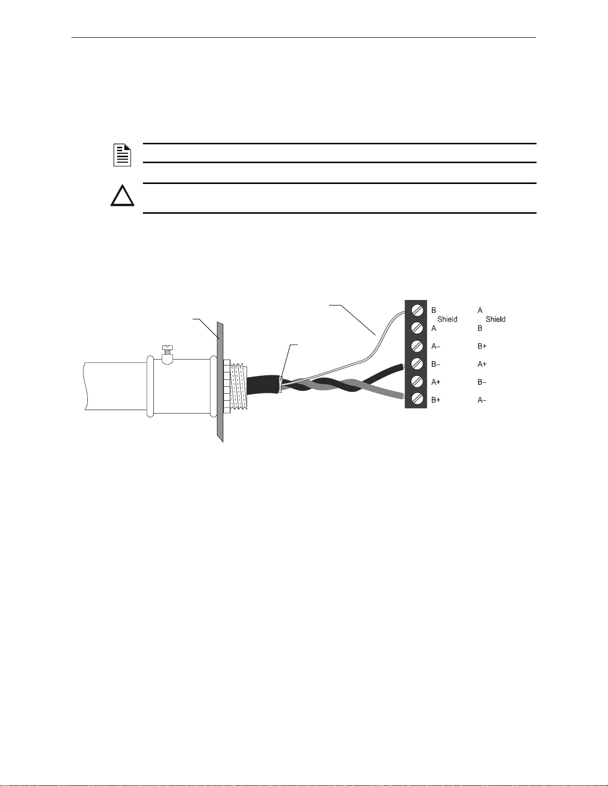
!
Cabinet
SLC-shieldterm.wmf
Shield Drain Wire
Shield Foil
Conduit
MS-9600
MS-9600LS
MS-9600UDLS
MS-9200UD
MS-9200UDLS
MS-9050UD
MS-9200
Figure 2.5 Shield Termination
2.3 Shield Wire Termination
The drawing below shows the method of proper termination of the shield.
Connect the metal conduit to the cabinet by using the proper connector. Feed the shielded wire
through the conduit, into the control box. The shield drain wire must be connected to the “shield”
terminal on the SLC terminal block.
NOTE: Use of good wiring practice consistent with local electrical codes is expected.
CAUTION: DO NOT LET THE SHIELD DRAIN WIRE OR THE SHIELD FOIL TOUCH THE
SYSTEM CABINET OR BE CONNECTED TO EARTH GROUND AT ANY POINT.
FireLite SLC Wiring Manual — P/N 51309:P4 9/17/2014 17
Page 18
Wiring Requirements Control Panel Terminal Blocks
TB6
SHIELD SLC SLC
TB4
SLC-9200tb.wmf
SLC
Return
SLC Out
Connections for wire shield
Unregulated Power
Nonresettable Power
Resettable Power
Figure 2.6 MS-9200 Terminal Blocks
TB8
SHIELDSLC SLC SLC SLC
TB3
SLC Return
SLC Out
Connections for
wire shield
Nonresettable
Power
Resettable Power
SLC-9600tb.wmf
Figure 2.7 MS-9600 Series Terminal Blocks
2.4 Control Panel Terminal Blocks
The terminal blocks on the control panel circuit board that concern the SLC circuit are described
below. For more information on this subject refer to the control panel’s Instruction Manual.
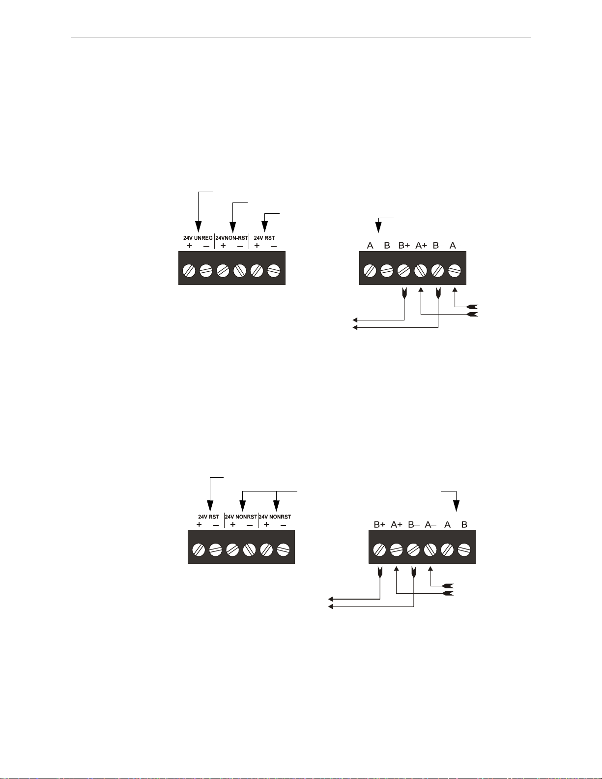
2.4.1 MS-9200
TB4 provides three types of 24 VDC power; Unregulated, Nonresettable and Resettable.
TB6 provides connections for the SLC wiring.
198 addresses are available per loop (99 detectors and 99 modules).
2.4.2 MS-9600, MS-9600LS, & MS-9600UDLS
TB3 provides two types of 24 VDC power; Nonresettable and Resettable.
TB8 provides connections for the SLC wiring.
198 addresses are available per loop (99 detectors and 99 modules) while operating in CLIP mode.
318 addresses are available per loop (159 detectors and 159 modules) while operati ng in LiteSp eed
mode.
18 FireLite SLC Wiring Manual — P/N 51309:P4 9/17/2014
Page 19
Control Panel Terminal Blocks Wiring Requirements
TB10
SLC
TB1
SLC Out
Connections for
wire shield
Resettable Powerjumper selectable by JP6
Nonresettable Power- jumper selectable by JP4
SLC-9200udtb.wmf
SLC Return
Figure 2.8 MS-9200UDLS (Rev 3) Terminal Blocks
TB10
SLC
TB1
SLC Out
Connections for
wire shield
Resettable
Power
Nonresettable Power
SLC-9200udtb.wmf
SLC Return
Figure 2.9 MS-9200UD & MS-9200UDLS (Rev 1 & 2) Terminal Blocks
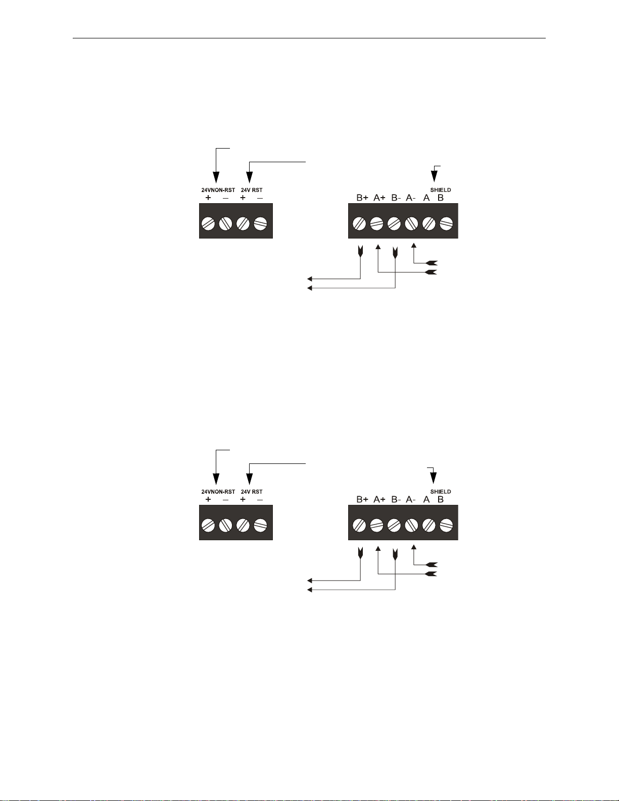
2.4.3 MS-9200UDLS (Software Version 3.0)
TB1 provides two types of 24 VDC power; Nonresettable and Resettable, jumper selectable by JP4
and JP6.
TB10 provides connections for the SLC wiring.
198 addresses are available per loop (99 detectors and 99 modules).
2.4.4 MS-9200UD & MS-9200UDLS (Versions 1 and 2)
TB1 provides two types of 24 VDC power; Nonresettable and Resettable.
TB10 provides connections for the SLC wiring.
198 addresses are available per loop (99 detectors and 99 modules).
FireLite SLC Wiring Manual — P/N 51309:P4 9/17/2014 19
Page 20
Wiring Requirements Control Panel Terminal Blocks
SLC Out
Connections for wire shield
SLC-9050udtb.wmf
SLC Return
Figure 2.10 MS-9050UD Terminal Block
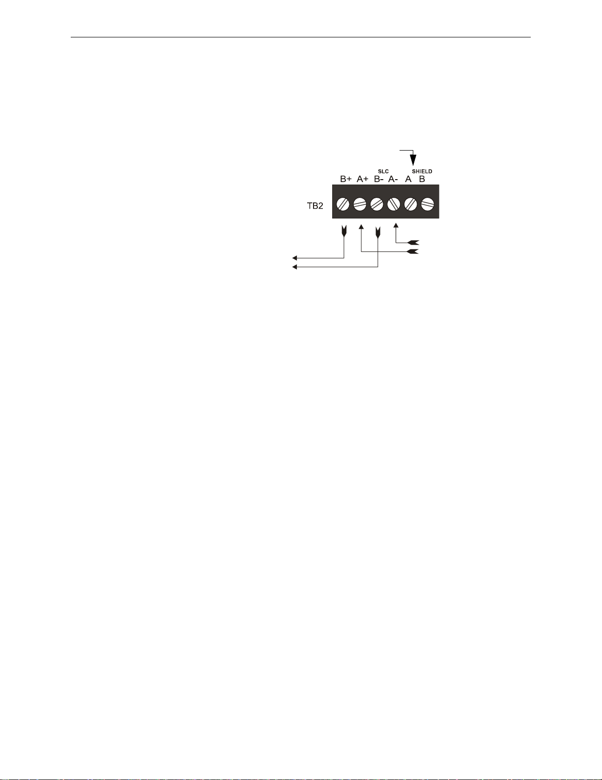
2.4.5 MS-9050UD
24 VDC power may be supplied by a remote power supply such as the Fire-Lite FCPS-24FS6/8.
TB2 provides connections for the SLC wiring.
50 addresses are available (any combination of detectors and modules).
20 FireLite SLC Wiring Manual — P/N 51309:P4 9/17/2014
Page 21
Section 3: SLC Circuits without Isolators
SLC-style4.wmf
Two-wire Addressable Detector
Addressable Module
T-tapped Circuits
Control Panel
SLC
B+ B–
Figure 3.1 Basic NFPA Style 4 SLC
3.1 Overview
This chapter concerns itself with the two styles of circuits that do not require isolation devices:
• NFPA Style 4
• NFPA Style 6
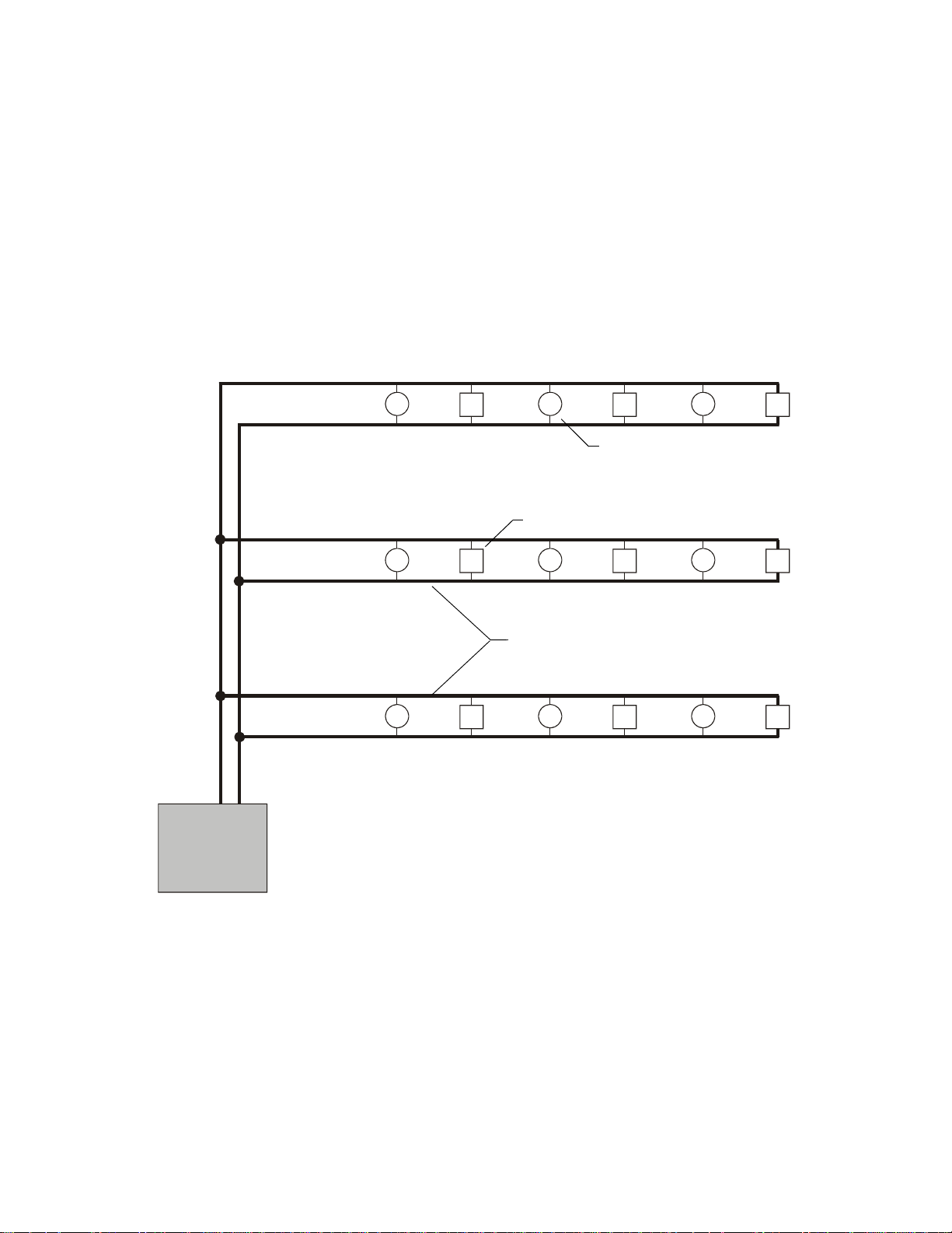
3.2 NFPA Style 4 SLC
NFPA Style 4 requirements can be met by using the diagram below.
• T-tapping of the SLC wiring is allowed for Style 4 configuration.
FireLite SLC Wiring Manual — P/N 51309:P4 9/17/2014 21
Page 22
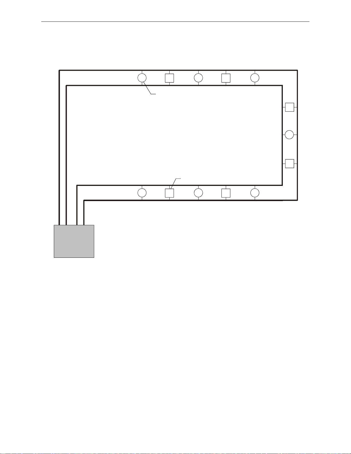
SLC Circuits without Isolators NFPA Style 6 SLC
Control Panel
SLC
Two-wire Addressable Detector
Addressable Module
SLC-style6.cdrwmf
SLC Return
SLC Out
B+ B– A– A+
Figure 3.2 Basic NFPA Style 6 SLC
3.3 NFPA Style 6 SLC
NFPA Style 6 requirements can be met by using the diagram below.
• T-tapping of the SLC wiring is NOT allowed for Style 6 configuration.
22 FireLite SLC Wiring Manual — P/N 51309:P4 9/17/2014
Page 23

Section 4: SLC Circuits with Isolators
!
4.1 Fault Isolator Devices
There are three isolator devices used to protect critical elements of the SLC from faults on other
SLC branches or segments.
• Fault Isolator Module I300
• Six Fault Isolator Module ISO-6
• Isolator Detector Base B224BI
A Fault Isolator Module on both sides of a device, or the combination of Isolator Base and Isolator
Module is required to comply with NFPA Style 7 requirements.
CAUTION: MAXIMUM ADDRESSABLE DEVICES
• If relay or sounder bases are not used, a maximum of 25 addressable devices can be
connected between Isolator Modules and/or Bases. When relay or sounder bases are used,
the maximum number of addressable devices that can be connected between Isolators is
reduced to seven. Isolator modules will not function properly when these limits are exceeded.
• When more than 100 Isolator Modules are connected to an SLC loop, the address capacity
of the loop is reduced by two (2) addresses for every isolator device in excess of 100.
4.1.1 Isolating an SLC Branch
The module continuously monitors the circuit connected to terminals 3(–) and 4(+). Upon powerup, an integral relay is latched on. The module periodically pulses the coil of this relay. A short circuit on the SLC resets the relay. The module detects the short and disconnects the faulted SLC
branch or segment by opening the positive side of the SLC (terminal 4). This isolates the faulty
branch from the remainder of the loop preventing a communication problem with all other addressable devices on the remaining branches (labeled “Continuation of the SLC” in the figure below).
During a fault condition, the control panel registers a trouble condition for each addressable device
which is isolated on the SLC segment or branch. Once the fault is removed, the module automatically reapplies power to the SLC branch or segment.
FireLite SLC Wiring Manual — P/N 51309:P4 9/17/2014 23
Page 24
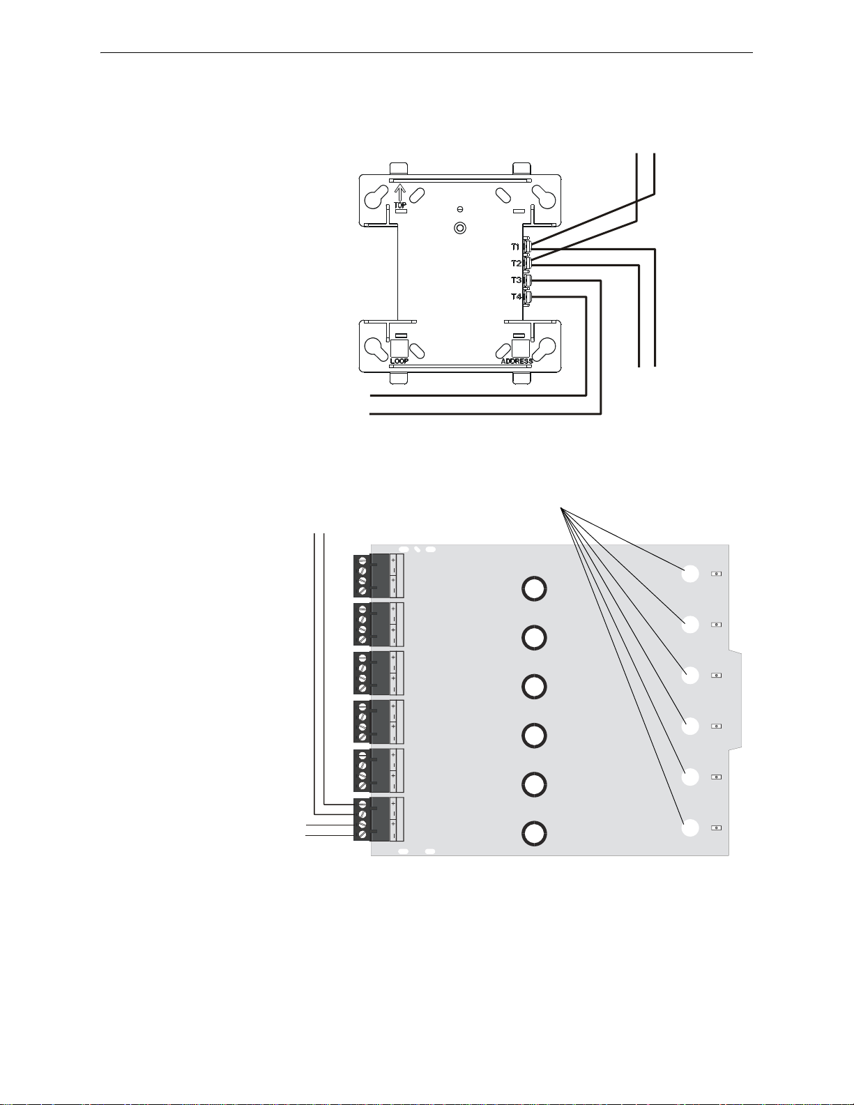
SLC Circuits with Isolators Fault Isolator Devices
(-)
(+)
(-)
(+)
SLC
Isolated branch
of the SLC
SLC-isowire2.wmf
Continuation
of the SLC
OUT
OUT
IN
IN
Figure 4.1 Wiring an I300 Module
ISOLATOR 1
ISOLATOR 2
ISOLATOR 3 ISOLATOR 4
ISOLATOR 5
ISOLATOR 6
iso-6wire.wmf
SLC in from FACP
or previous device
Figure 4.2 Wiring an ISO-6 Module
SLC out to
next device
status indicators
+
-
+
-
4.1.2 Wiring an Isolator Module
The figure below shows typical wiring of an I300Isolator Module:
The figure below shows typical wiring of an ISO-6 Isolator Module:
24 FireLite SLC Wiring Manual — P/N 51309:P4 9/17/2014
Page 25
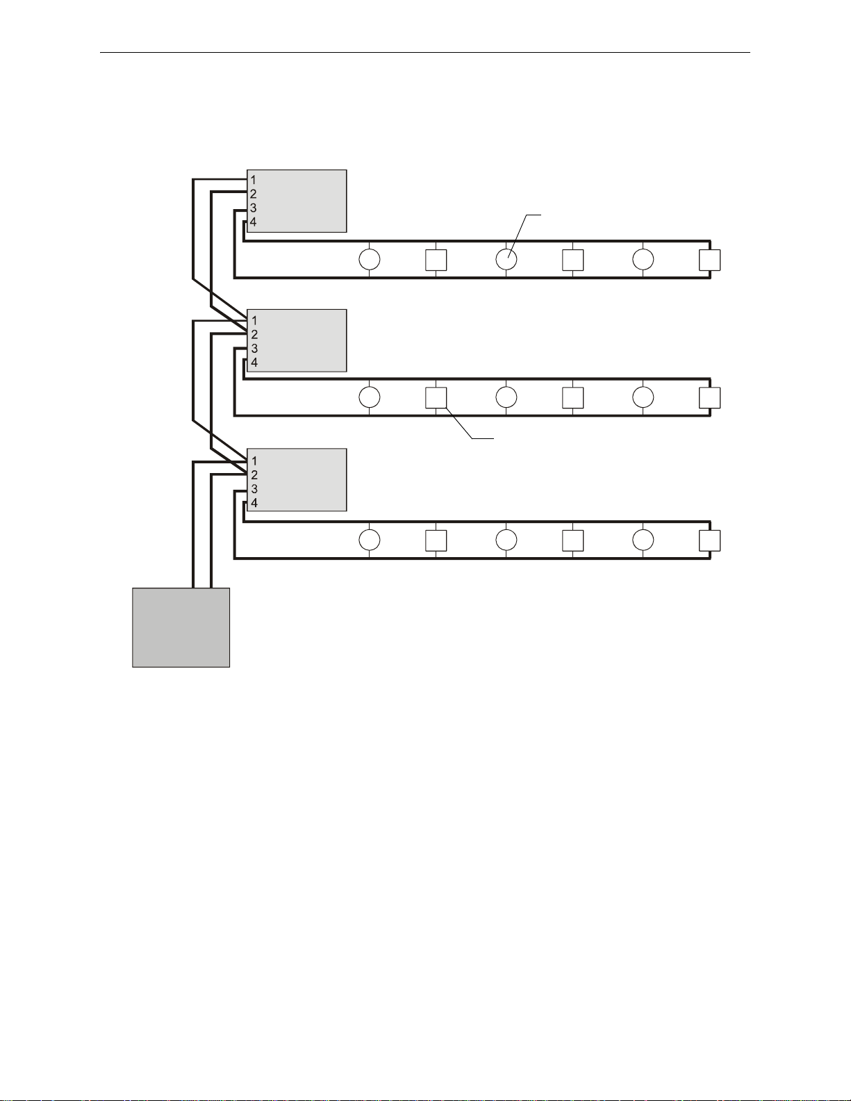
NFPA Style 4 SLC Using Isolator Modules SLC Circuits with Isolators
Figure 4.3 NFPA Style 4 SLC Using an I300 Isolator Module
Two-wire Addressable Detector
Addressable Pull Station
SLC-style4iso.wmf
Control Panel
SLC
B– B+
Isolated Branch
Isolator Module
Isolator Module
Isolator Module
Isolated Branch
Isolated Branch
4.2 NFPA Style 4 SLC Using Isolator Modules
A variation of a Style 4 operation using an I300 isolator module to protect each branch of the SLC
is shown below. Refer to Figure 4.1 for I300 wiring and to Section 4.1 for limitations.
FireLite SLC Wiring Manual — P/N 51309:P4 9/17/2014 25
Page 26
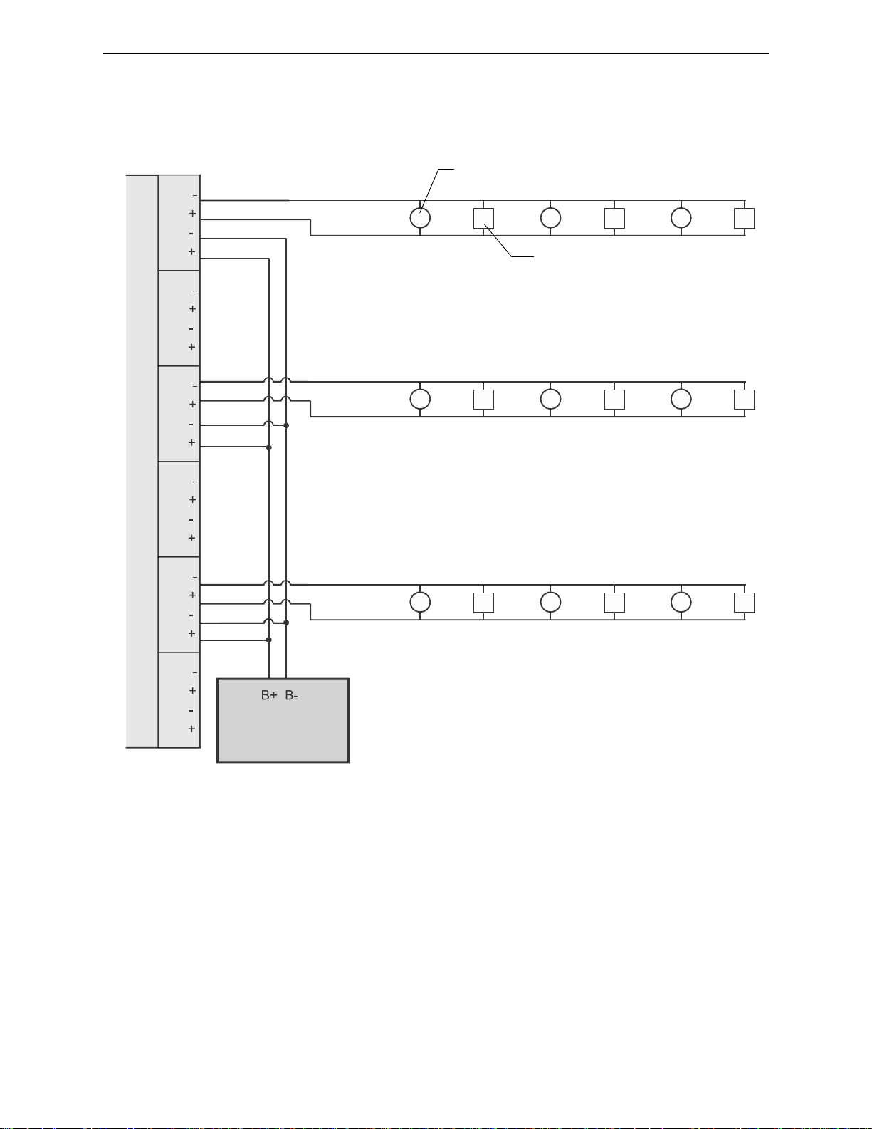
SLC Circuits with Isolators NFPA Style 4 SLC Using Isolator Modules
Figure 4.4 NFPA Style 4 SLC Using an ISO-6 Isolator Module
Two-wire Addressable Detector
Addressable Pull Station
Control Panel
SLC
ISO-6
ISOLATOR 1
Out Out +
In In +
SLC-style4ISO-6.wmf
ISOLATOR 2ISOLATOR 3ISOLATOR 4ISOLATOR 5ISOLATOR 6
Isolated Branch
Isolated Branch
Isolated Branch
A variation of a Style 4 operation using an ISO-6 isolator module to protect each branch of the SLC
is shown below. Each terminal on the ISO-6 acts as a single I300 module. Refer to Figure 4.2 for
ISO-6 wiring and to Section 4.1 for limitations. Note that the ISO-6 cannot accept two wires at one
pin. Wire Style 4 SLC loops as shown in the figure below.
26 FireLite SLC Wiring Manual — P/N 51309:P4 9/17/2014
Page 27
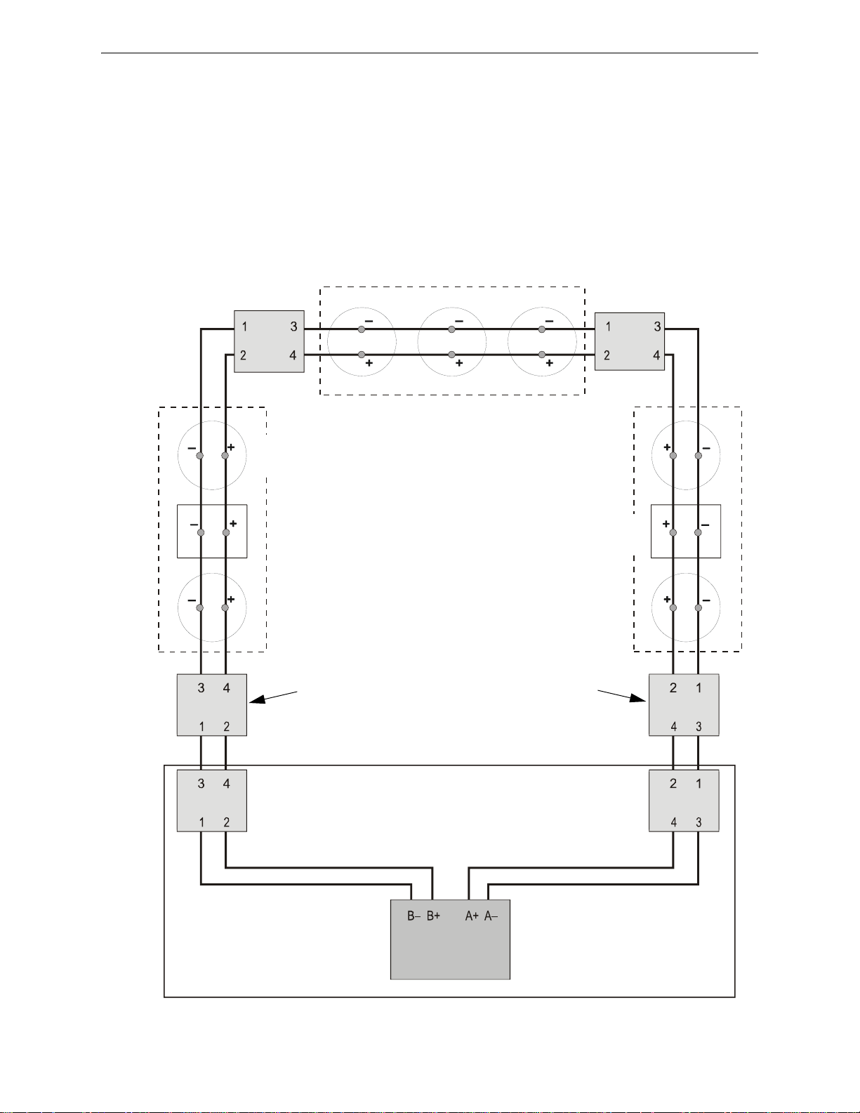
NFPA Style 6 SLC Using Isolator Modules SLC Circuits with Isolators
Figure 4.5 NFPA Style 6 SLC Using Isolator Modules
SLC Out SLC Return
SLC-style6iso.wmf
Control Panel
Two-wire
Addressable
Detector
Section B
Section C
Section A
Isolator
Module
Isolator
Module
Isolator
Module
Additional isolator module required when first device in the
section is more than 20 feet from the control panel.
Isolator
Module
Isolator
Module
Isolator
Module
Addressable
Pull Station
4.3 NFPA Style 6 SLC Using Isolator Modules
A variation of Style 6 operation using isolator modules to protect a section of the SLC. By flanking
each group of devices with an I300 fault isolator module each group is protected from faults that
may occur in the other groups. For example, a fault in Section B will not effect Sections A & C.
The isolator modules on either side of Section B will open the loop. Section A will still operate
from power on the SLC Out side and Section C will operate from the SLC Return side.
• A combination of isolator modules and isolator bases may be used.
• T-tapping is NOT allowed within the Style 6 configuration.
• Isolator modules shall be within 20 feet (6.1 meters) of device and must be enclosed in metal
conduit.
FireLite SLC Wiring Manual — P/N 51309:P4 9/17/2014 27
Page 28
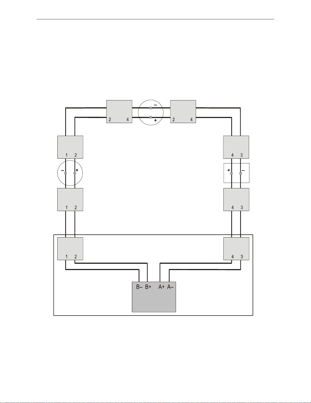
SLC Circuits with Isolators NFPA Style 7 SLC Using Isolator Modules
2
1
3
4
3
4
3
4
1
3
1
32121
SLC-style7iiso.wmf
SLC Out
SLC Return
Two-Wire
Addressable
Detector
Addressable
Pull Station
Control Panel
Two-wire
Addressable
Detector
Figure 4.6 NFPA Style 7 SLC Using Isolator Modules
Isolator
Module
Isolator
Module
Isolator
Module
Isolator
Module
Isolator
Module
Isolator
Module
Isolator
Module
Isolator
Module
4.4 NFPA Style 7 SLC Using Isolator Modules
Style 7 operation requires using isolator modules (or a combination of isolator modules and isolator
bases) before and after each device. Flanking each device with an isolator provides fault protection
to all other devices on the loop.
• T-tapping is NOT allowed wi thin the Style 7 wiring configuration.
• When a detector base or pull station is used, install isolator modules on both sides of the
device.
• Connections between isolator modules and the device they isolate must be “close-nippled”
conduit, within 3 feet (91.44 cm).
28 FireLite SLC Wiring Manual — P/N 51309:P4 9/17/2014
Page 29
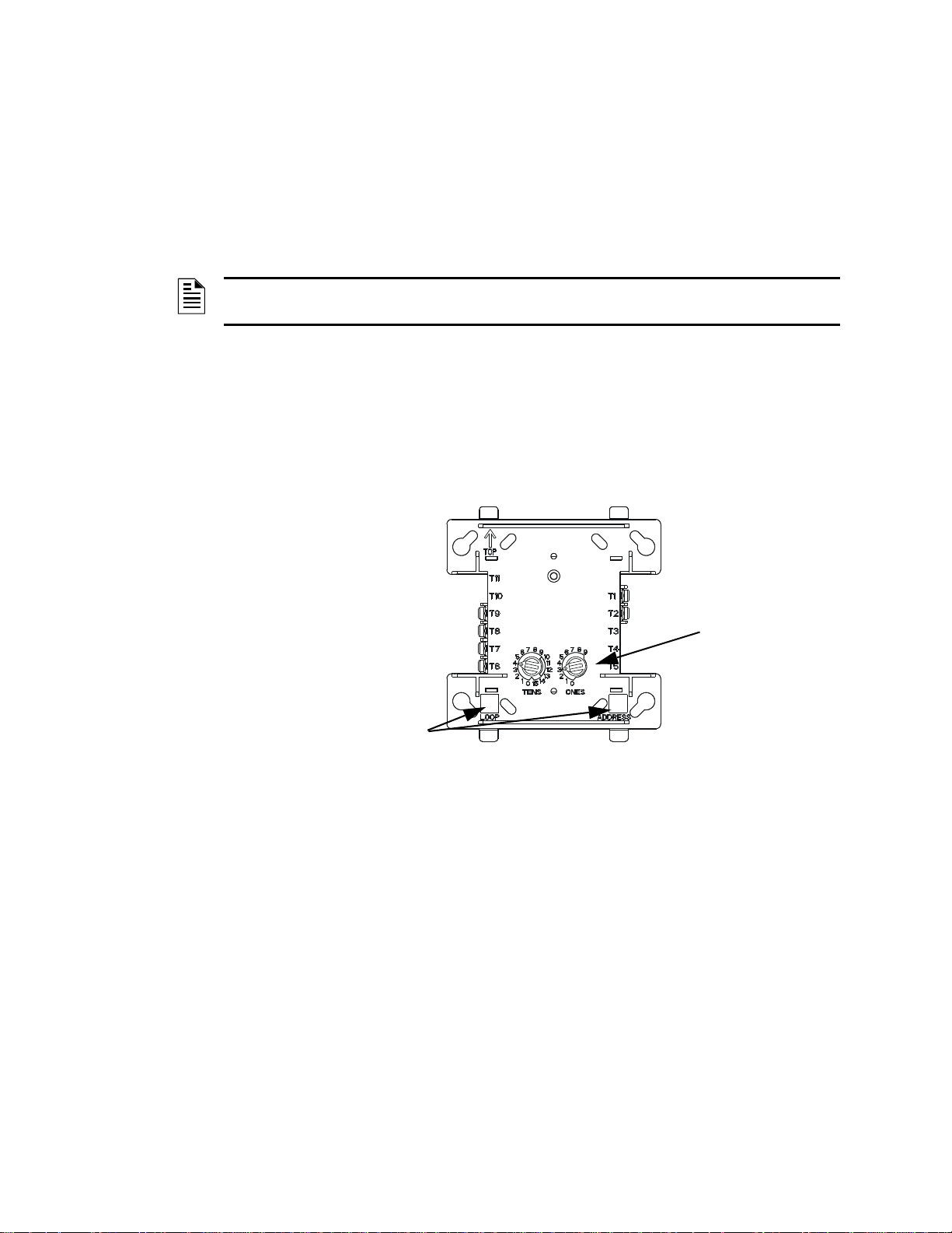
Section 5: Monitor Modules
SLC–
SLC+
IDC Return –
IDC Return +
IDC Out +
IDC Out -
Rotary
Switches
Areas used to record the device
address and SLC number.
FMMtpH.wmf
Figure 5.1 MMF-300 Monitor Module
5.1 Descriptions
These addressable modules monitor conventional contact-type alarm initiating devices. You can
configure module circuits as an NFPA Style B (Class B) or Style D (Class A) Initiating Device Circuits (IDC). There is no limit to the number of contact-type devices installed on a monitor module
circuit.
NOTE: For more information on the individual module specifications refer to the Installation
Instructions that are provided with these devices.
5.1.1 Addressable Monitor Modules
MMF-300 Monitor Module
This is an addressable module that monitors either a Style B (Class B) or Style D (Class A) circuit
of dry-contact input devices. This module is capable of participating in degraded mode where supported by the FACP.
FireLite SLC Wiring Manual — P/N 51309:P4 9/17/2014 29
Page 30
Monitor Modules Descriptions
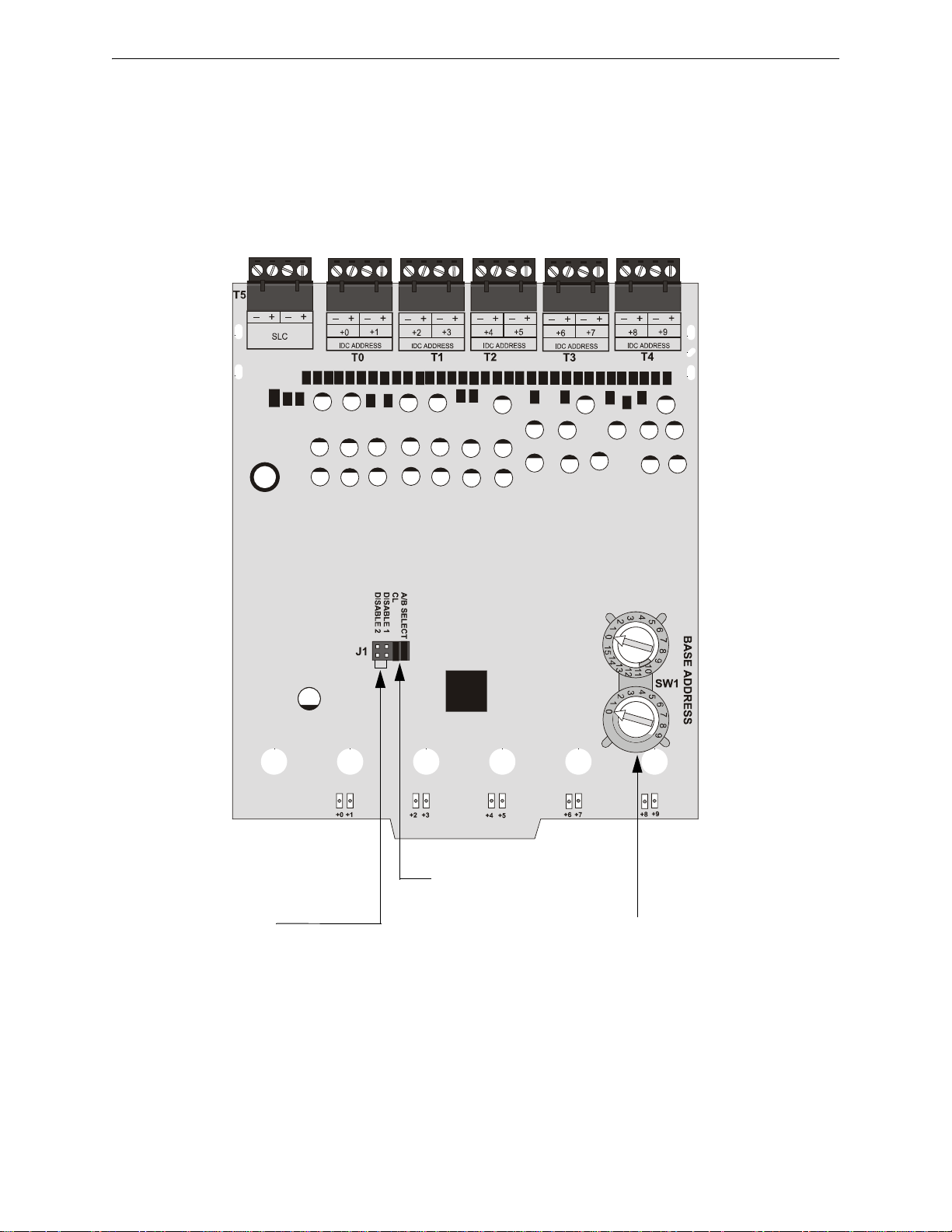
Disable Address
Place shunt in:
Disable 1 position to disable highest module address
Disable 2 position to disable highest two module addresses
Style Y or Style Z Select
Remove shunt for Style Z circuits
SLC Address
Set rotary switches to base
(first) address of modules
Figure 5.2 MMF-300-10 Monitor Module
m
m
f
-
3
0
0
-
1
0
.
w
m
f
MMF-300-10 Monitor Module
This is an addressable monitor module intended to interface between the FACP and up to ten (10)
Style B (Class B) or five (5) Style D (Class A) IDCs containing normally open contact devices.
This type of module is contained in either a BB-2 or BB-6 cabinet. The BB-2 can accommodate up
to 2 modules and the BB-6, which requires the CH-6 chassis, can accommodate up to 6 modules.
See the Installation Instructions provided with module for proper installation into a cabinet.
30 FireLite SLC Wiring Manual — P/N 51309:P4 9/17/2014
Page 31
Descriptions Monitor Modules
FZMtpH.wmf
Rotary
Switches
SLC–
SLC+
24 VDC –
24 VDC +
IDC Return –
IDC Return +
IDC Out +
IDC Out -
Areas used to record the device
address and SLC number.
Figure 5.3 MMF-302 Interface Module
5.1.2 Zone Interface Modules
MMF-302 Module
Similar to the MMF-300, this module is used to monitor a single IDC of UL listed compatible twowire 24 volt conventional smoke detectors. Refer to the Device Compatibility Document.
FireLite SLC Wiring Manual — P/N 51309:P4 9/17/2014 31
Page 32
Monitor Modules Descriptions
– +
– +
T6
J1
BASE ADDRESS +0 BASE ADDRESS +1 BASE ADDRESS +2
BASE ADDRESS +3
BASE ADDRESS +4 BASE ADDRESS +5
A/B SELECT
A/B SELECT
DISABLE 1
DISABLE 2
T1
T0
T2
T3
T4
T5
SW1
BASE ADDRESS
0
1
2
3
4
5
6
7
8
9
10
11
13
14
15
12
0
1
2
3
4
5
6
7
8
9
– +
– +
– +
– +
– +
– +
– +
– +
Disable Address
Place shunt in:
Disable 1 position to disable highest module address
Disable 2 position to disable highest two module addresses
Style Y or Style Z Select
Remove shunt for Style Z circuits
SLC Address
Set rotary switches to base
(first) address of modules
Figure 5.4 MMF-302-6 Interface Module
MMF-302-6 Interface Module
This monitor module is intended to interface between the FACP and a conventional alarm system
with up to six (6) Style B (Class B) or three (3) Style D (Class A) IDCs containing normally open
contact devices.
This type of module is contained in either a BB-2 or BB-6 cabinet. The BB-2 can accommodate up
to 2 modules and the BB-6, which requires the CH-6 chassis, can accommodate up to 6 modules.
See the Installation Instructions provided with module for proper installat ion into cabinet.
32 FireLite SLC Wiring Manual — P/N 51309:P4 9/17/2014
Page 33
Installation Monitor Modules
fmmtph.wmf
Rotary
Switches
SLC–
SLC+
9 H–
8 H+
7L+
6L–
Address +1
{
Base Address {
Areas used to record the device
address and SLC number.
Figure 5.5 MDF-300 Dual Monitor Module
FMM-101.wmf
Label – Use to record
the device address and
SLC number.
Rotary Switches
IDC (+)
IDC (-)
SLC (+)
SLC (-)
Figure 5.6 MMF-301 Mini Monitor Module
5.1.3 Dual Monitor Module
MDF-300 Module
The MDF-300 is similar to the MMF-300 but provides for two independent 2-wire IDCs at two
separate, consecutive addresses.
5.1.4 Mini Monitor Module
MMF-301 Monitor Module
The MMF-301 is functionally and electrically identical to an MMF-300, but is offered in a smaller
package for mounting directly in the electrical box of the Style B (Class B) device being monitored.
5.2 Installation
When installing any of these modules DO NOT mix the following services that the IDC provides:
• Fire alarm service
• Automatic and manual waterflow alarm service with normally open contact devices
• Sprinkler supervision with normally open contact devices
FireLite SLC Wiring Manual — P/N 51309:P4 9/17/2014 33
Page 34
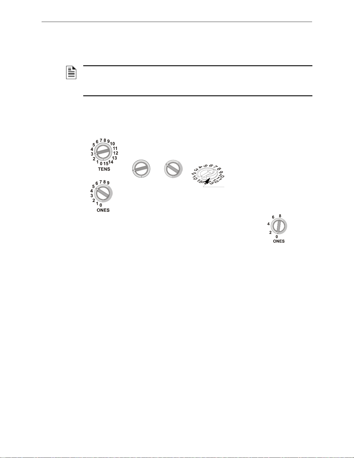
Monitor Modules Installation
TENS
8
9
10
11
12
13
14
15
0
1
2
3
4
5
6
7
ONES
8
9
0
1
2
3
4
5
6
7
Breakaway Tab - Modules come with
a raised breakaway tab on the TENS
rotary switch. This tab must be
removed when the module is on an
FACP that uses more than 99
addresses.
SLC-setadd.cdr,SLC-setaddtpH.wmf, SLCbrktabs.wmf
Dual monitor modules: On dual monitor modules, only even
numbers appear on the ONES rotary switch. The module takes
both the selected address and the next-higher address.
Modules with
Rotary Switches
in vertical
position
Modules with Rotary
Switches in
horizontal position
Figure 5.7 Setting an SLC Address on a Single Point Module
5.2.1 Setting an SLC address for a Single Point Module
Each module can be set to one of 159 addresses (01-159) and is factory preset with an address of
“00”.
NOTE: The MS-9050UD can support addresses 01 - 50. The MS-9200, MS-9200UD, and MS9200UDLS can support module addresses of 01 - 99. The MS-9600, MS-9600LS, and MS9600UDLS can support module addresses 01 - 159. The plastic stop located on the Tens switch
must be removed to set addresses above 99.
T o set an SLC address, use a screwdriver to adjust the rotary switches on the module to the desired
address. The module below is set at “35”. When finished, mark the address on the module face in
the place provided.
34 FireLite SLC Wiring Manual — P/N 51309:P4 9/17/2014
Page 35
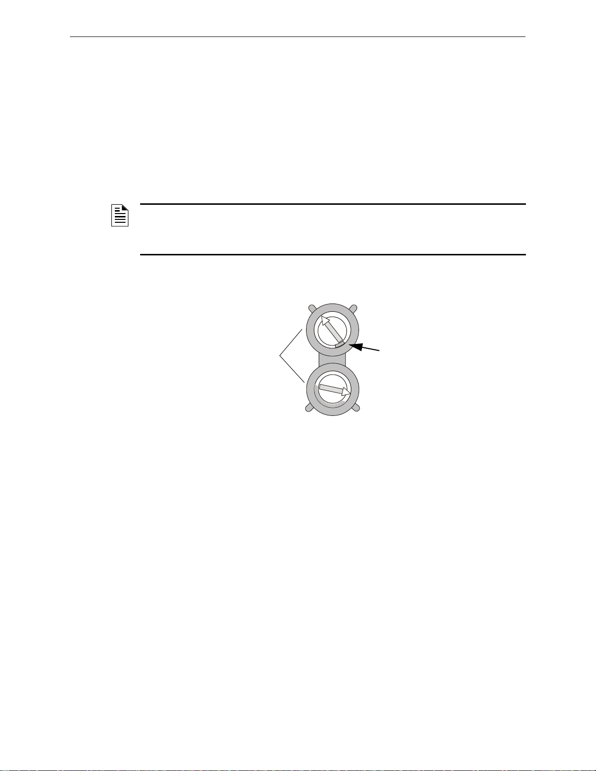
Installation Monitor Modules
0
1
2
3
4
5
6
7
8
9
10
11
13
14
15
12
0
1
2
3
4
5
6
7
8
9
multroty.wmf
Rotary Switches
Plastic Stop
TENS
ONES
Figure 5.8 Setting an SLC Address on a Multi-Point Module
5.2.2 Setting an SLC address for a Multi-Point Module
The SLC address of a multi-point module is set in the same fashion as a single-point module.
In Class B operation, each MMF-300-10, MMF-302-6, CMF-300-6, and CRF-300-6 module is set
to a base address. The remaining module points are automatically assigned to the next higher SLC
addresses. For example, if the base address of a MMF-300-10 is set to 28, the next module points
will be addressed to 29, 30, 31, 32, 33, 34, 35, 36 and 37.
In Class A operation, alternate module points are paired together, resulting in a total of five module
points. For example, if the base address of a MMF-300-10 is set to 28, then 30, 32, 34 and 36 will
be automatically assigned to the remaining module points and 29, 31, 33, 35 and 37 are available
for use by other modules.
NOTE: The MS-9050UD can support addresses 01 - 50. The MS-9200, MS-9200UD and MS9200UDLS can support module addresses of 01 - 99. The MS-9600, MS-9600LS, and MS9600UDLS can support module addresses 01 - 159 (the plastic stop located on the Tens switch
must be removed to set addresses above 99).
To set an SLC address, use a common screwdriver to adjust the rotary switches on the module to
the desired address. The module below is set at “28”.
FireLite SLC Wiring Manual — P/N 51309:P4 9/17/2014 35
Page 36
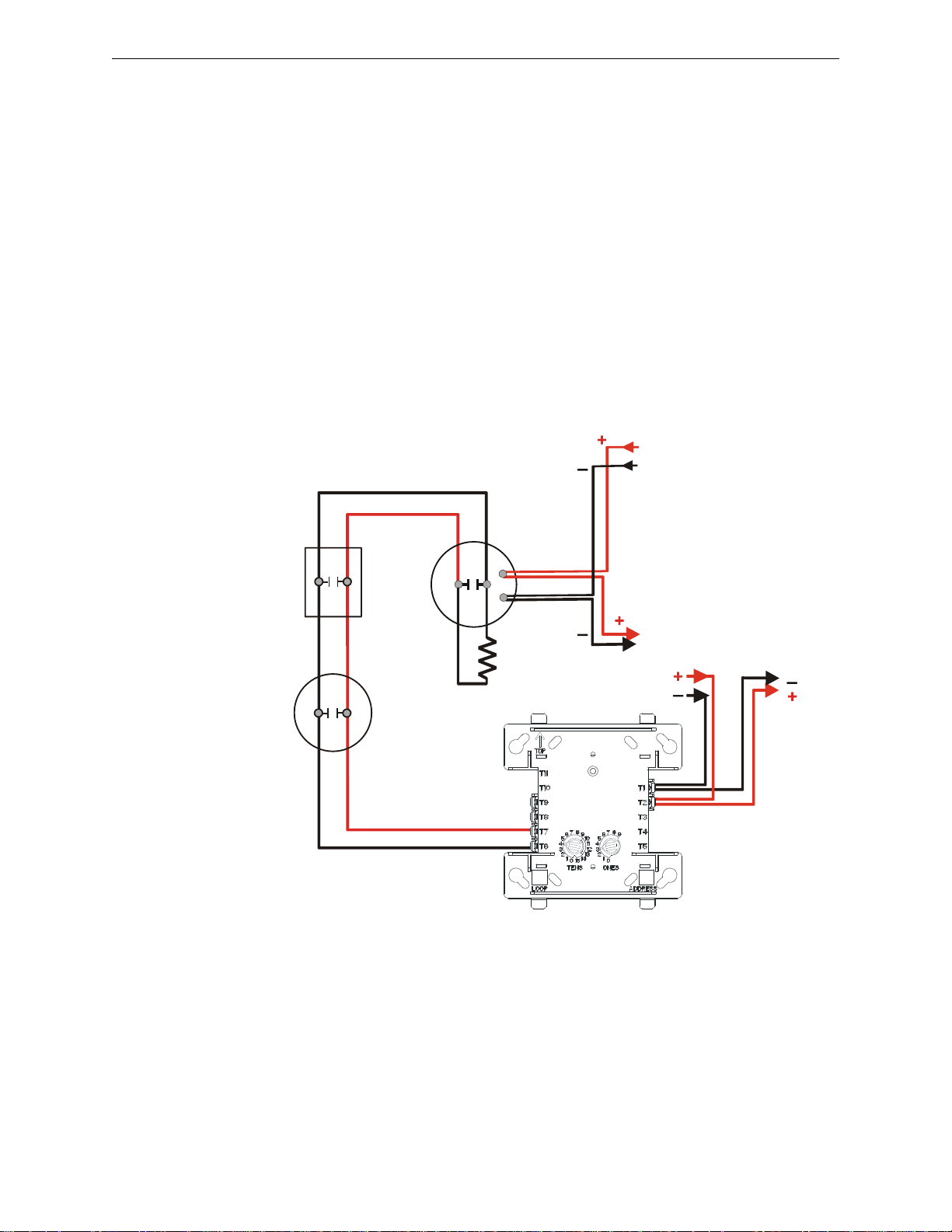
Monitor Modules MMF-300 Wiring Diagrams
47K ELR
(supplied
with module)
Heat
detector
SLC
MMF-300
IDC
24 VDC Power
Filtered, Regulated,
Resettable
24 VDC
Four-wire
Detector Base
Manual pull
station
From Supply
To Next IDC
or
Supervision Device
SLC-idcB1tpH.wmf
Figure 5.9 Typical Style B IDC Wiring with an MMF-300
5.3 MMF-300 Wiring Diagrams
Following are wiring diagrams that depict NFPA Style B (Class B) and D (Class A) Initiating
Device Circuits (IDCs) using MMF-300 monitor modules.
The Initiating Device Circuit (IDC) is supervised and current-limited to 210 microamperes @ 24
VDC (nominal).
5.3.1 Wiring a NFPA Style B IDC with an MMF-300
Connect the SLC wiring to the module terminals 1 (–) and 2 (+).
Each module takes one address on the SLC. Use the rotary switches on the module to set it to the
required SLC address. Refer to “Setting an SLC address for a Single Point Module” on page 34.
The figure below shows typical wiring for a supervised and power-limited NFPA Style B IDC
using an MMF-300 module.
• Refer to the Device Compatibility Document for compatible smoke detectors.
• See “Power Considerations” on page 68 for information on supervising 24 VDC power.
36 FireLite SLC Wiring Manual — P/N 51309:P4 9/17/2014
Page 37
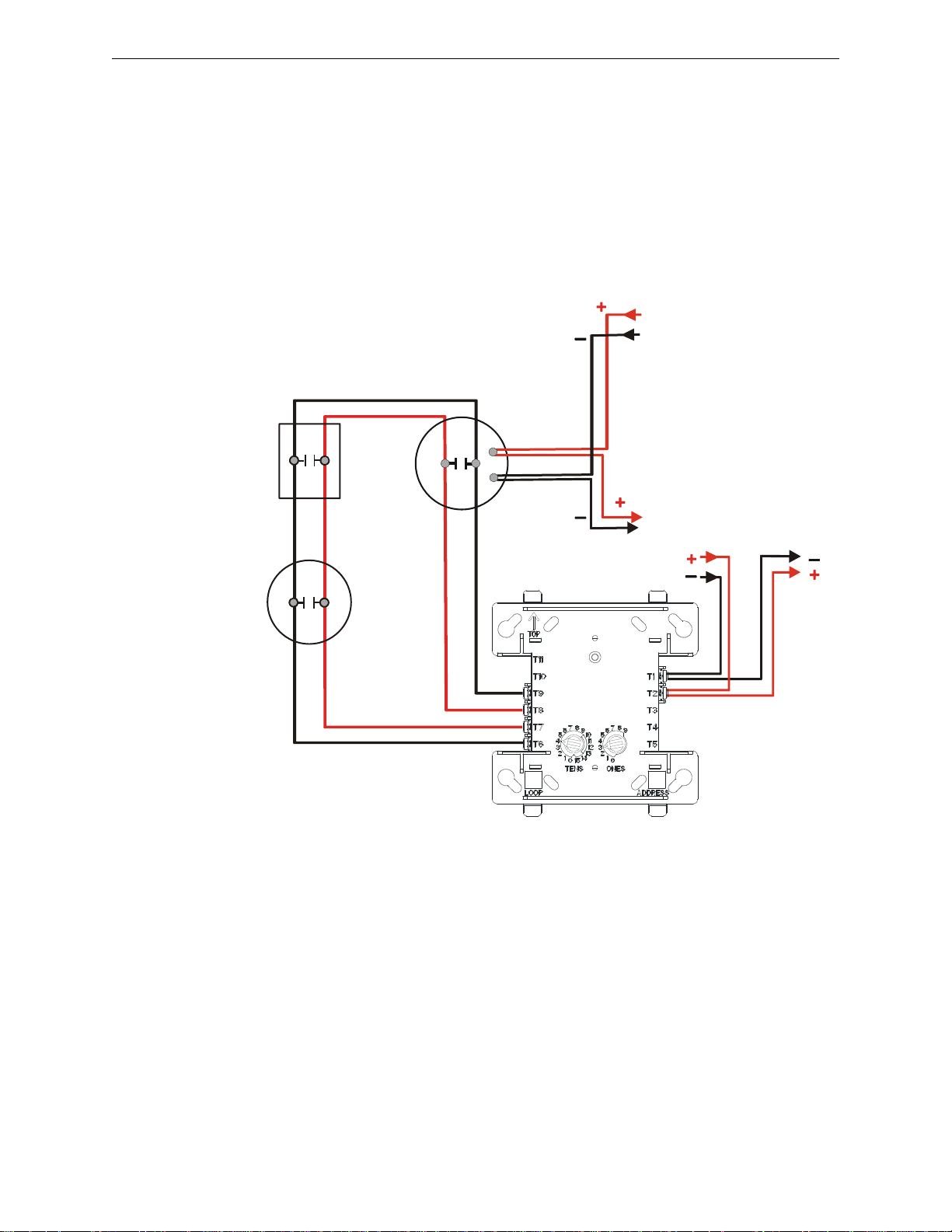
MMF-300 Wiring Diagrams Monitor Modules
SLC-idcD1tpH.wmf
24 VDC
Four-wire
Detector Base
Heat
detector
SLC
MMF-300
IDC
24 VDC Power
Filtered, Regulated,
Resettable
From
Supply
To Next IDC
or
Supervision Device
Manual pull
station
Figure 5.10 Typical Style D IDC Wiring with an MMF-300
5.3.2 Wiring a NFPA Style D IDC with an MMF-300
Connect the SLC wiring to the module terminals 1 (–) and 2 (+).
Each module takes one address on the SLC. Use the rotary switches on the module to set it to the
required SLC address. Refer to “Setting an SLC address for a Single Point Module” on page 34.
The figure below shows typical wiring for a supervised and power-limited NFP A Style D (Class A)
IDC using an MMF-300 module.
• Refer to the Device Compatibility Document for compatible smoke detectors.
• See “Power Considerations” on page 68 for information on supervising 24 VDC power.
FireLite SLC Wiring Manual — P/N 51309:P4 9/17/2014 37
Page 38

Monitor Modules MMF-300 Wiring Diagrams
++-
-
47K ELR
(supplied
with module)
SLC
MMF-300 Module
programmed for Tornado,
Hazard, or Medical operation.
Refer to the control panel
installation manual.
IDC
UL-listed Signaling
applicance such as the
Fire-Lite FSS-2400E
SLC-emer.wmf
Figure 5.11 Emergency Signaling Wiring with an MMF-300
5.3.3 MMF-300 Wiring for Emergency Alarm System Applications
Connect the SLC wiring to the module terminals 1 (–) and 2 (+).
Each module takes one address on the SLC. Use the rotary switches on the module to set it to the
required SLC address. Refer to “Setting an SLC address for a Single Point Module” on page 34.
The figure below shows typical wiring for a supervised and power-limited Emergency Signaling
circuit using an MMF-300 module.
• See “Power Considerations” on page 68 for information on supervising 24 VDC power.
• See Section 6, “Contro l Modu les” for instructions on using control modules as NACs on an
SLC.
• For compatible output devices refer to the Device Compatibility Document #15384.
38 FireLite SLC Wiring Manual — P/N 51309:P4 9/17/2014
Page 39
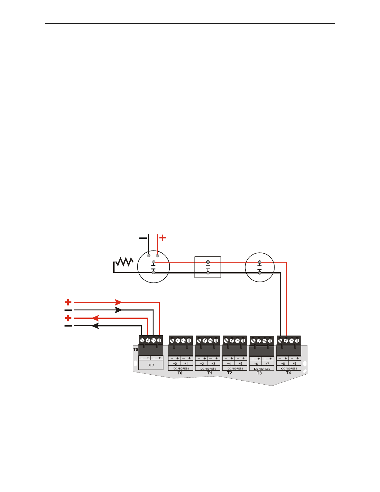
MMF-300-10 Wiring Diagrams Monitor Modules
24 VDC Power
Filtered, Regulated, Resettable
24 VDC Four-wire
Detector Base
Manual Pull
Station
Heat
Detector
MMF-300-10
SLC
47K ELR
(supplied
with module)
IDC
Out
SLC-idcB4.wmf
Figure 5.12 Typical Style B IDC Wiring with an MMF-300-10
5.4 MMF-300-10 Wiring Diagrams
Following are wiring diagrams that depict NFPA Style B (Class B) and D (Class A) Initiating
Device Circuits (IDCs) using MMF-300-10 monitor modules.
The Initiating Device Circuit (IDC) is supervised and current-limited to 1.0 milliampere @ 24
VDC (nominal).
5.4.1 Wiring a NFPA Style B IDC with an MMF-300-10
Connect the SLC wiring to the module terminals T5 as shown below.
Use the rotary switches on the module to set the base SLC address. Each module takes ten
addresses on the SLC. The remaining module points are automatically assigned to the next nine
higher addresses. Refer to “Setting an SLC address for a Multi-Point Module” on page 35.
DO NOT set the lowest address above 150 (41 for the MS-9050UD, 90 for the MS-9200, MS9200UD, and MS-9200UDLS), as the other module points will be assigned to nonexistent
addresses.
The figure below shows typical wiring for a supervised and power-limited NFPA Style B IDC
using an MMF-300-10 module.
• Refer to the Device Compatibility Document for compatible smoke detectors.
• See “Power Considerations” on page 68 for informat ion on supervising 24 VDC power.
FireLite SLC Wiring Manual — P/N 51309:P4 9/17/2014 39
Page 40
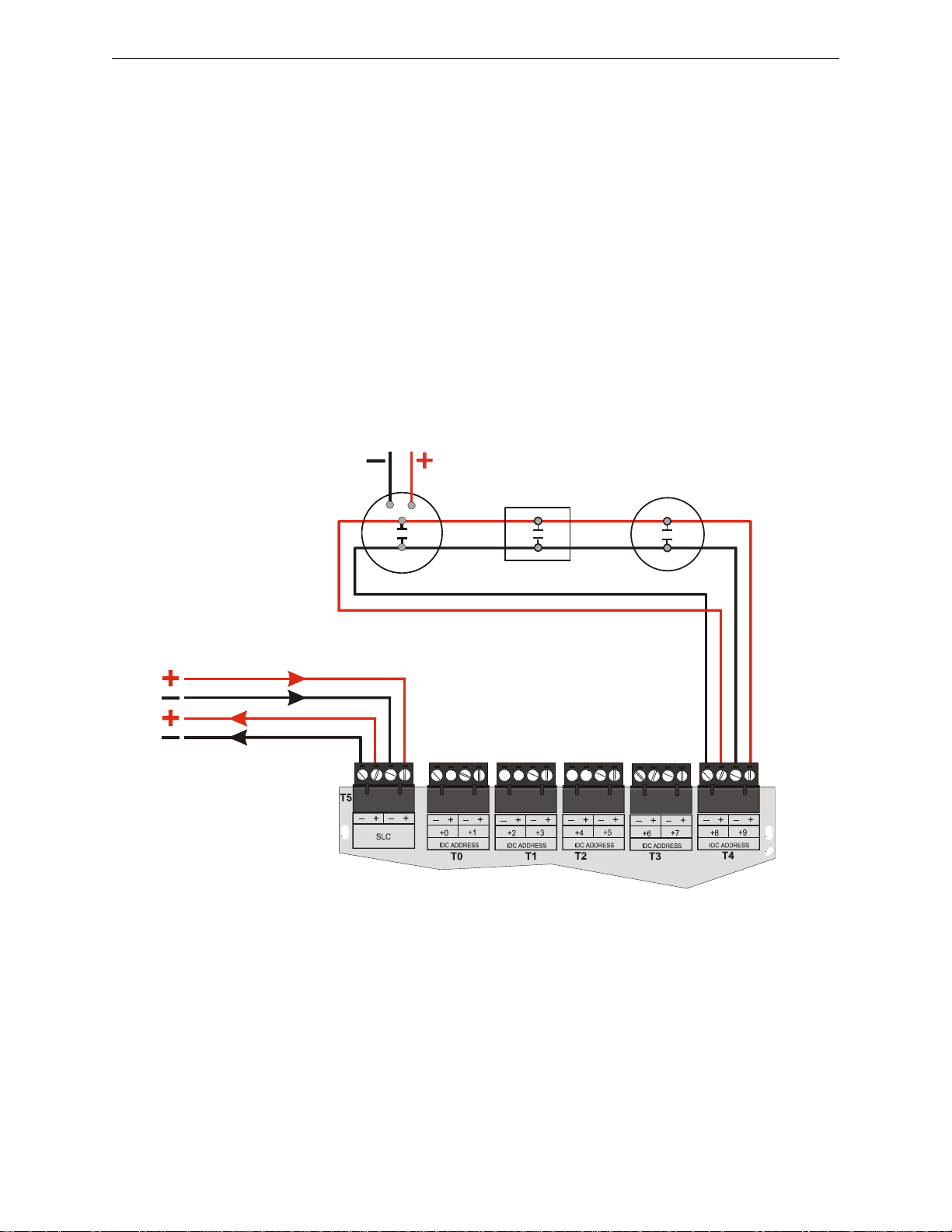
Monitor Modules MMF-300-10 Wiring Diagrams
24 VDC Power
Filtered, Regulated, Resettable
24 VDC Four-wire
Detector Base
Manual Pull
Station
Heat
Detector
IDC
Out
MMF-300-10
SLC
IDC
Return
SLC-idcD3.cdwmf
Figure 5.13 Typical Style D IDC Wiring with an MMF-300-10
5.4.2 Wiring a NFPA Style D IDC with an MMF-300-10
Connect the SLC wiring to the module terminals T5 as shown below.
Use the rotary switches on the module to set the base SLC address. Each module takes five alternat-
ing addresses on the SLC. The remaining module points are automatically assigned to the next four
higher addresses. (Example: 28, 30, 32, 34 and 36). Refer to “Setting an SLC address for a MultiPoint Module” on page 35.
DO NOT set the lowest address above 150 (41 for the MS-9050UD, 90 for the MS-9200, MS9200UD, and MS-9200UDLS), as the other module points will be assigned to nonexistent
addresses.
The figure below shows typical wiring for a supervised and power-limited NFP A Style D (Class A)
IDC using an MMF-300-10 module.
• Refer to the Device Compatibility Document for compatible smoke detectors.
• See “Power Considerations” on page 68 for information on supervising 24 VDC power.
40 FireLite SLC Wiring Manual — P/N 51309:P4 9/17/2014
Page 41
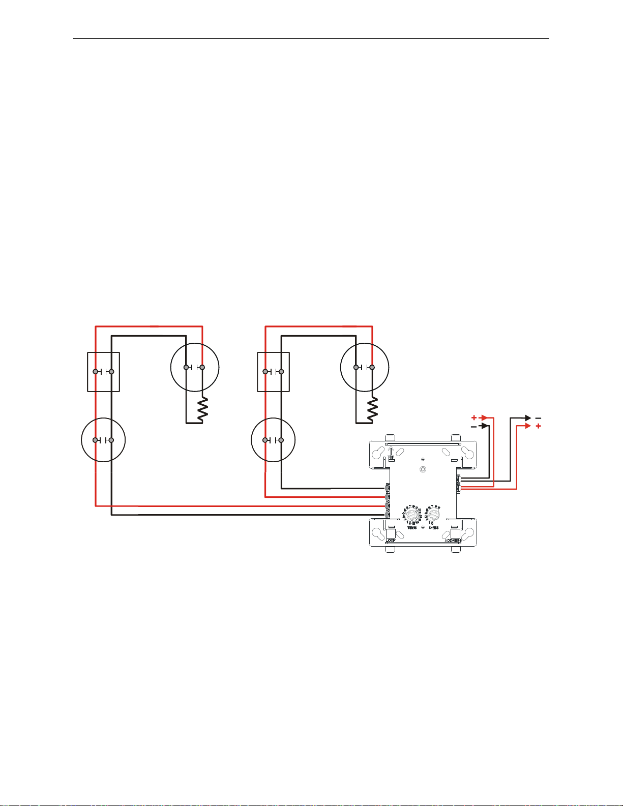
MDF-300 Wiring Diagrams Monitor Modules
T11
T10
T9
T8
T7
T6
T1
T2
T3
T4
T5
SLC-idcB3fdm1tph.wmf
Heat
Detector
Manual
Pull
Station
SLC
MDF-300
Base +1 Address
(IDC Circuit H)
Base Address
(IDC Circuit L)
47K
ELR
47K
ELR
Manual
Pull
Station
Figure 5.14 Typical Style B IDC Wiring with an MDF-300
5.5 MDF-300 Wiring Diagrams
Following is a wiring diagrams that depict NFPA Style B (Class B) Initiating Device Circuits
(IDCs) using MDF-300 Dual Monitor Modules.
5.5.1 Wiring a NFPA Style B IDC with an MDF-300
Connect the SLC wiring to the module terminals 1 (–) and 2 (+).
Use the rotary switches on the module to set it to the SLC address. Each dual module takes two
addresses on the SLC. Circuit ‘L’ correspond s to the address set on the rotary switches, which will
be an even number. Circuit ‘H’ will automatically respond to the next higher address, which will be
an odd number. Use caution to avoid duplicate addressing of modules on the system. Refer to “Setting an SLC address for a Single Point Module” on page 34.
Each IDC (H & L) is power limited to 230 microamperes @ 24 VDC.
The figure below shows typical wiring for a supervised and power-limited NFPA Style B IDC
using an MDF-300-10 module.
• Refer to the Device Compatibility Document for compatible smoke detectors.
• See “Power Considerations” on page 68 for informat ion on supervising 24 VDC power.
FireLite SLC Wiring Manual — P/N 51309:P4 9/17/2014 41
Page 42
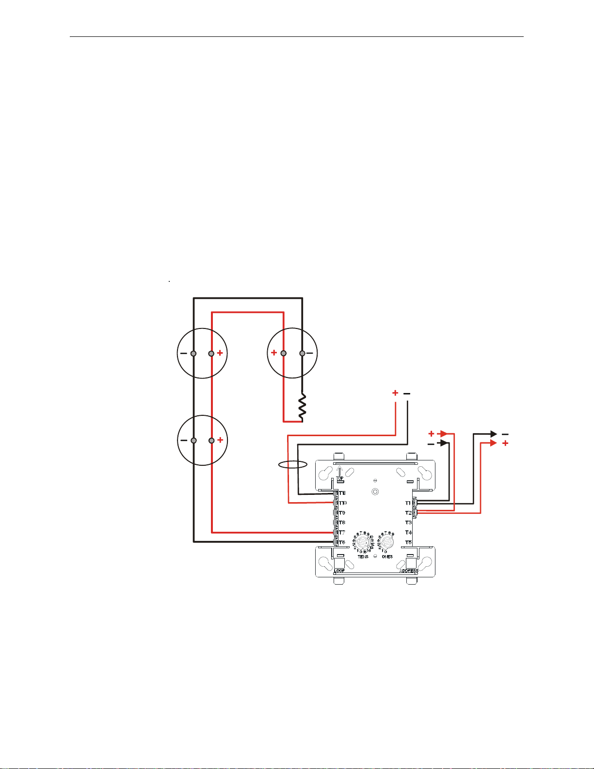
Monitor Modules MMF-302 Wiring Diagrams
SLC
IDC
SLC-idcB2tpH.wmf
MMF-302
Two-wire
smoke
detectors
3.9K ELR
(supplied with module)
24 VDC Resettable power.
90 mA External 24 volt
supply required
Figure 5.15 Typical Style B IDC Wiring with an MMF-302
5.6 MMF-302 Wiring Diagrams
Following are wiring diagrams that concern NFPA Style B (Class B) and D (Class A) Initiating
Device Circuits (IDCs) using MMF-302 Zone Interface Modules.
5.6.1 Wiring a NFPA Style B IDC with an MMF-302
Connect the SLC wiring to the module terminals 1 (–) and 2 (+).
Each module takes one address on the SLC. Use the rotary switches on the module to set it to the
required SLC address. Refer to “Setting an SLC address for a Single Point Module” on page 34.
The IDC is supervised and power limited to 230 microamperes @ 24 VDC.
The figure below shows typical wiring for a supervised and power-limited NFPA Style B IDC
using an MMF-302 module.
• Refer to the Device Compatibility Document for compatible smoke detectors.
• 24 VDC power must be provided from a UL listed power supply for fire protection use. This
power is inherently supervised by the module.
• See “Power Considerations” on page 68 for informat ion on 24 VDC power.
42 FireLite SLC Wiring Manual — P/N 51309:P4 9/17/2014
Page 43
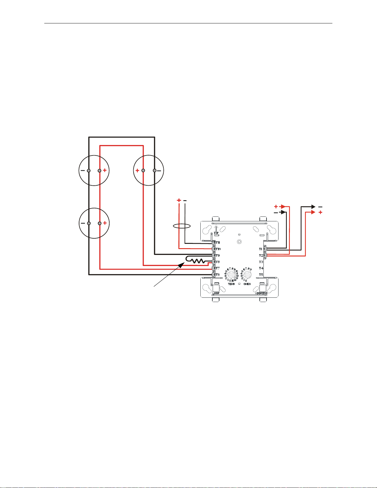
MMF-302 Wiring Diagrams Monitor Modules
SLC
Two-wire
smoke
detectors
3.9K ELR
(supplied with module)
IDC
MMF-302
SLC-idcD2tpH.wmf
24 VDC Resettable power.
90 mA External 24 volt supply required
Figure 5.16 Typical Style D IDC Wiring with an MMF-302
5.6.2 Wiring a NFPA Style D IDC with an MMF-302
Connect the SLC wiring to the module terminals 1 (–) and 2 (+).
Each module takes one address on the SLC. Use the rotary switches on the module to set it to the
required SLC address. Refer to “Setting an SLC address for a Single Point Module” on page 34.
The figure below shows typical wiring for a supervised and power-limited NFP A Style D (Class A)
IDC using an MMF-302 module.
• Refer to the Device Compatibility Document for compatible smoke detectors.
• 24 VDC power must be provided from a UL listed power supply for fire protection use. This
power is inherently supervised by the module.
• See “Power Considerations” on page 68 for informat ion on 24 VDC power.
FireLite SLC Wiring Manual — P/N 51309:P4 9/17/2014 43
Page 44
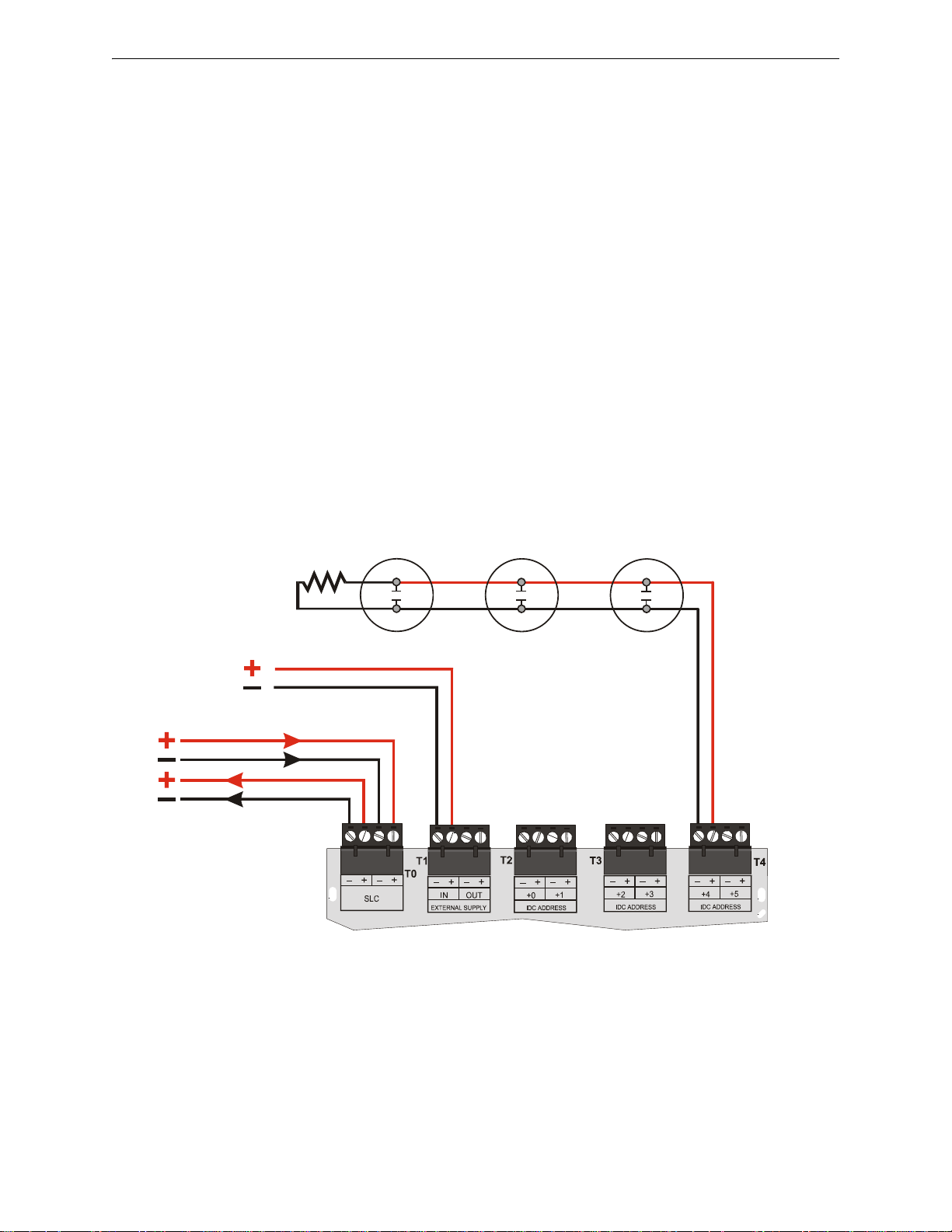
Monitor Modules MMF-302-6 Wiring Diagrams
Two-wire smoke detectors
IDC
Out
MMF-302-6
24 VDC resettable power
3.9K ELR
(supplied with
module)
SLC-idcB5.wmf
SLC
Figure 5.17 Typical Style B IDC Wiring with an MMF-302-6
5.7 MMF-302-6 Wiring Diagrams
Following are wiring diagrams that concern NFPA Style B (Class B) and D (Class A) Initiating
Device Circuits (IDCs) using MMF-302-6 monitor modules.
5.7.1 Wiring a NFPA Style B IDC with an MMF-302-6
Connect the SLC wiring to the module terminals T0 as shown below.
Use the rotary switches on the module to set the base SLC address. Each module takes six
addresses on the SLC. The remaining module points are automatically assigned to the next five
higher addresses. Refer to “Setting an SLC address for a Multi-Point Module” on page 35.
DO NOT set the lowest address above 150 (41 for the MS-9050UD, 90 for the MS-9200, MS9200UD, and MS-9200UDLS), as the other module points will be assigned to nonexistent
addresses.
The figure below shows typical wiring for a supervised and power-limited NFPA Style B IDC
using an MMF-302-6 module.
• Refer to the Device Compatibility Document for compatible smoke detectors.
• 24 VDC power must be provided from a UL listed power supply for fire protection use. This
power is inherently supervised by the module.
• See “Power Considerations” on page 68 for informat ion on 24 VDC power.
44 FireLite SLC Wiring Manual — P/N 51309:P4 9/17/2014
Page 45
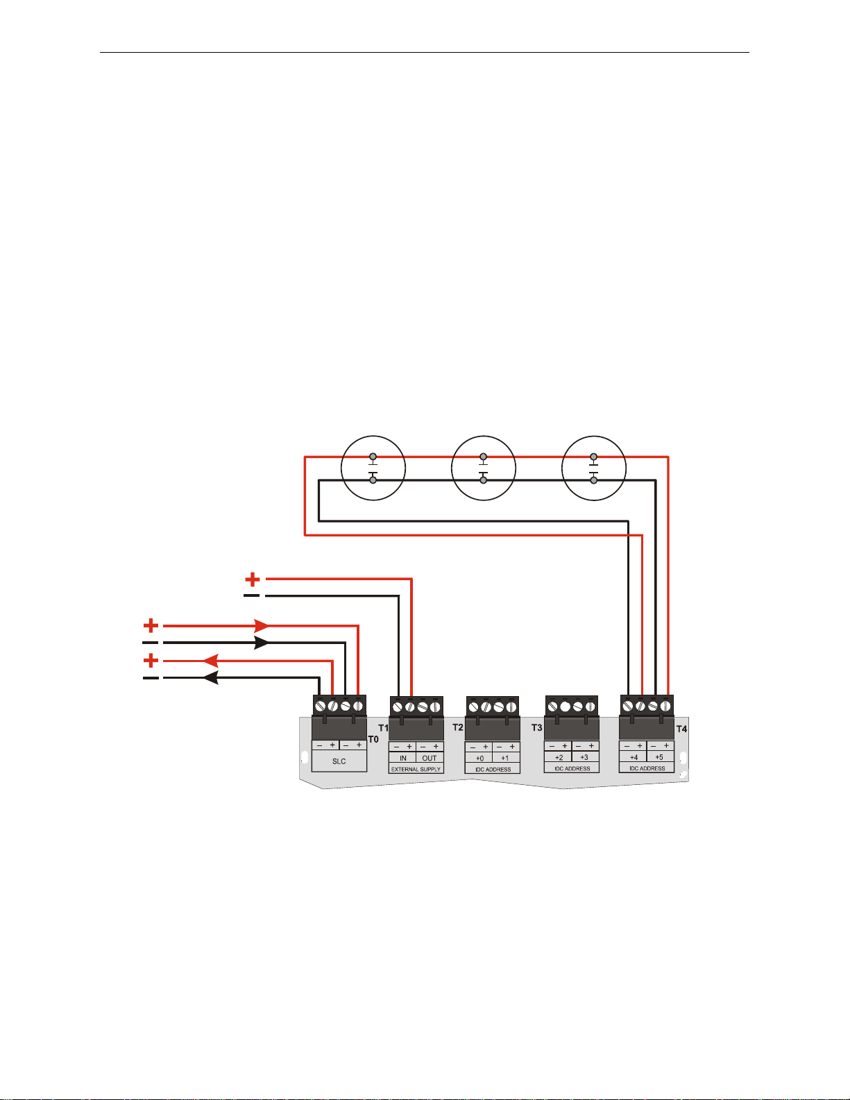
MMF-302-6 Wiring Diagrams Monitor Modules
SLC-idcD4.wmf
Two-wire smoke detectors
24 VDC resettable power
MMF-302-6
IDC
Out
SLC
IDC
Return
Figure 5.18 Typical Style D IDC Wiring with an MMF-302-6
5.7.2 Wiring a NFPA Style D IDC with an MMF-302-6
Connect the SLC wiring to the module terminals T0 as shown below.
Use the rotary switches on the module to set it to the SLC addresses. Each module takes three alter-
nating addresses on the SLC. The remaining module points are automatically assigned to the next
two higher addresses. (Example: 28, 30 and 32). Refer to “Setting an SLC address for a MultiPoint Module” on page 35.
DO NOT set the lowest address above 150 (41 for the MS-9050UD, 90 for the MS-9200, MS9200UD, and MS-9200UDLS), as the other module points will be assigned to nonexistent
addresses.
The figure below shows typical wiring for a supervised and power-limited NFP A Style D (Class A)
IDC using an MMF-302-6 module.
• Refer to the Device Compatibility Document for compatible smoke detectors.
• 24 VDC power must be provided from a UL listed power supply for fire protection use. This
power is inherently supervised by the module.
• See “Power Considerations” on page 68 for informat ion on 24 VDC power.
FireLite SLC Wiring Manual — P/N 51309:P4 9/17/2014 45
Page 46
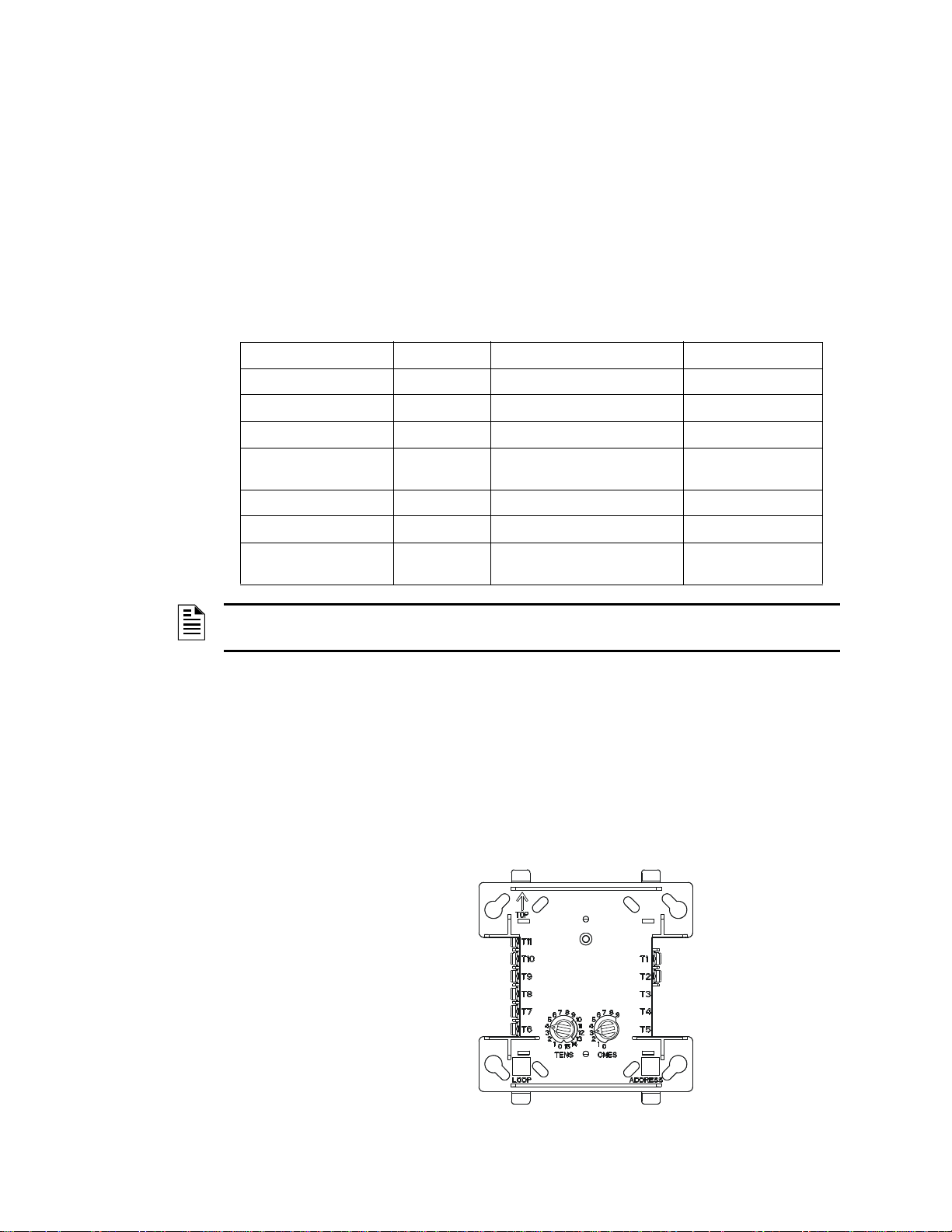
When using a Control Module as a Notification Appliance Circuit (NAC), the isolation described in
FCMFZMtph.wmf
NOTE: Module polarities are shown in alarm condition.
Style Z NAC (+)
Style Z NAC (–)
Style Y/Z NAC (–)
Style Y/Z NAC (+)
24 VDC Nonresettable Power (–)
24 VDC Nonresettable Power (+)
SLC (–)
SLC (+)
Figure 6.1 CMF-300 Wiring Connections
the section titled Section 4, “SLC Circuits with Isolators” which begins on page 23 , is required or
Riser Conductors must be installed in accordance with the survivability from attack by fire requirements in National Fire Alarm Code, NFPA 72.
6.1 Description
The CMF-300 and CMF-300-6 modules are addressable modules that can be used for monitoring
and switching 24 VDC Notification Appliance Circuit (NAC) power for NFPA Style Y (Class B)
and NFPA Style Z (Class A) circuits.
Ratings for the relay contacts on the module are:
Load Description Application Maximum Voltage Current Rating
Resistive Non-Coded 30 VDC 3.0 A
Resistive Coded 30 VDC 2.0 A
Resistive Non-Coded 110 VDC 0.9 A
Resistive Non-Coded 125 VAC (CMF-300)
Inductive (L/R = 5ms) Coded 30 VDC 0.5 A
Inductive (L/R = 2ms) Coded 30 VDC 1.0 A
Inductive (PF = 0.35) Non-Coded 125 VAC (CMF-300)
Section 6: Control Modules
0.9 A
70.7 VAC (CMF-300-6)
0.5 A
70.7 VAC (CMF-300-6)
NOTE: For more information on module specifications, refer to the Installation Instructions
provided with these devices.
6.2 CMF-300 Installation
6.2.1 Setting an SLC address for a CMF-300 Module
Each module is factory preset with an address of “00”. To set an SLC address refer to “Setting an
SLC address for a Single Point Module” on page 34.
6.2.2 Wiring a Notification Appliance Circuit (NAC) with a CMF-300
The figure below shows the connections to wire a module for powering a 24 VDC NAC:
46 FireLite SLC Wiring Manual — P/N 51309:P4 9/17/2014
Page 47
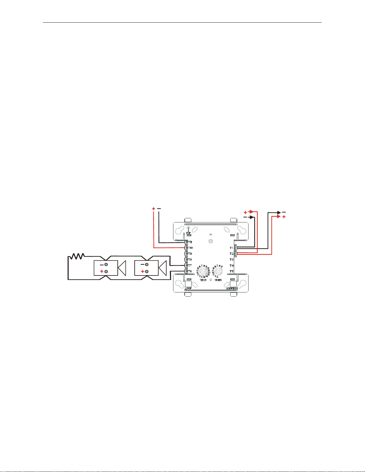
Wiring a CMF-300 Module Control Modules
CMF-300
NAC
24 VDC Nonresettable power
SLC
SLC-nacY.wmf
Note: Module polarities are shown in alarm condition
NOTE: A power
supervision relay is
required only on the
last module of the
power run.
ELR
47K, 1/2-watt
24 VDC Notification
Appliances
Figure 6.2 NFPA Style Y Notification Appliance Circuit
6.3 Wiring a CMF-300 Module
This section contains instructions and diagrams for wiring a Signaling Line Circuit with a
CMF-300 as a Notification Appliance Circuit (NAC).
6.3.1 Wiring a Style Y NAC (Two-Wire) with Addressable Control Modules
A supervised and power-limited NFPA Style Y (Class B) NAC using a CMF-300 module. Polarized alarm notification appliances are shown connected to the module in a two-wire configuration.
Refer to the Device Compatibility Document for compatible notification appliances and relays.
• See “Power Considerations” on page 68 for informat ion on monitoring 24 VDC power.
• Each module can control 2 amps of resistive load (on electronic devices) or 1 amp of inductive
load (on mechanical bells and horns).
• 24 VDC power must be provided from a UL listed power supply for fire protection use.
• A power supervision relay is required only on the last module of the power run.
• Do not T-tap or branch a Style Y circuit.
• Terminate the circuit across the last device using an End-of-Line Resistor 47K, 1/2-watt,
P/N SSD A2143-00 (ELR-47K in Canada).
• Do not loop wiring under the screw terminals of any notification appliance. To maintain
supervision, break the wire run at each device.
FireLite SLC Wiring Manual — P/N 51309:P4 9/17/2014 47
Page 48
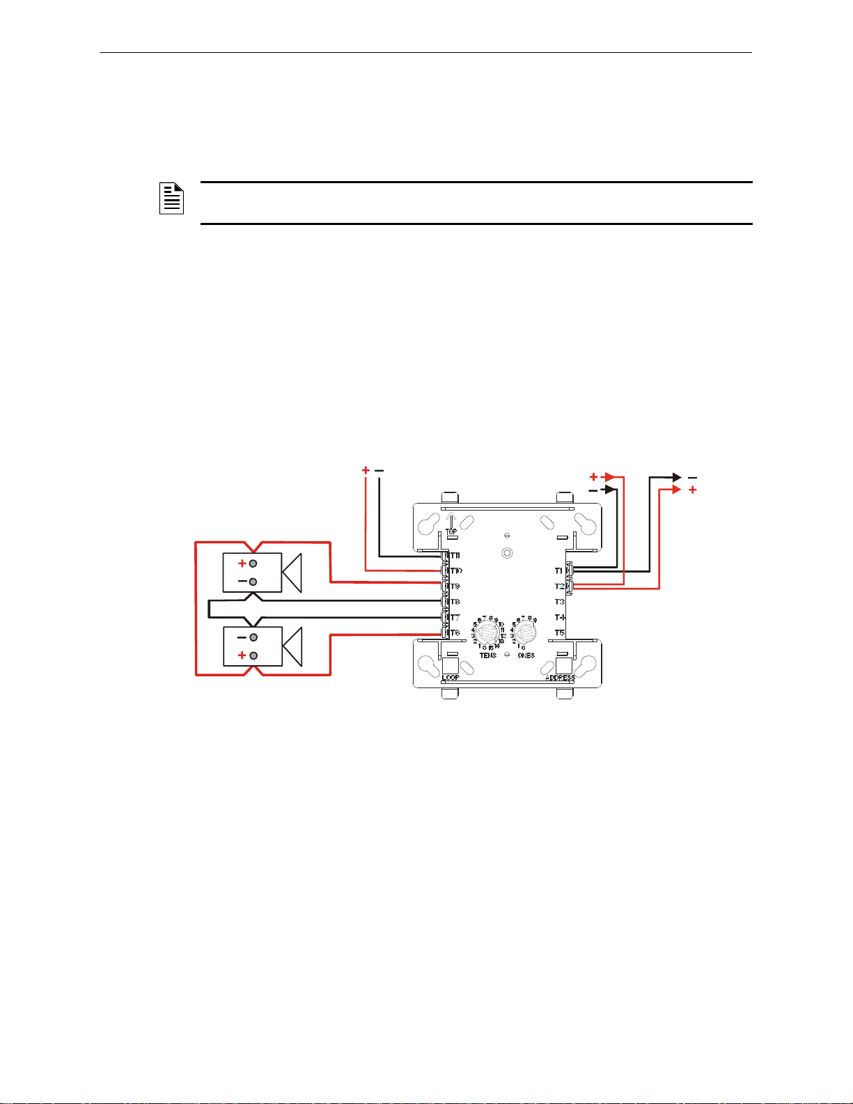
Control Modules CMF-300-6 Installation
24 VDC
notification
appliances
CMF-300
NAC Out
24 VDC Nonresettable power
SLC
SLC-nacZtpH.wmf
NAC Return
Note: Module polarities are shown in alarm condition.
NOTE: A power supervision relay is required only
on the last module of the power.
Figure 6.3 NFPA Style Z Notification Appliance Circuit
6.3.2 Wiring a Style Z NAC (Four-Wire) with Addressable Control Modules
A supervised and power-limited NFPA S tyle Z (Class A) NAC using a CMF-300 module. Polarized
alarm notification appliances are shown connected to the module in a four-wire configuration.
NOTE: Refer to the Device Compatibility Document for compatible notification appliances and
relays.
• See “Power Considerations” on page 68 for informat ion on monitoring 24 VDC power.
• Each module can control 2 amps of resistive load (on electronic devices) or 1 amp of inductive
load (on mechanical bells and horns).
• 24 VDC power must be provided from a UL listed power supply for fire protection use.
• A power supervision relay is required only on the last module of the power run.
• Do not T-tap or branch a Style Z circuit.
• Do not loop wiring under the screw terminals of any notification appliance. To maintain
supervision, break the wire run at each device.
6.4 CMF-300-6 Installation
6.4.1 Cabinet Installation
This type of module is contained in either a BB-2 or BB-6 cabinet. The BB-2 can accommodate up
to 2 modules and the BB-6, which requires the CH-6 chassis, can accommodate up to 6 modules.
See the Installation Instructions provided with module for proper installation into cabinet.
6.4.2 Setting an SLC address for an CMF-300-6 Module
In “Style Y” operation each CMF-300-6 module can be set to one of 154 base addresses (01-154).
The remaining module points are automatically assigned to the next five higher SLC addresses. For
example, if the base address is set to 28, the next five module points will be addressed to 29, 30, 31,
32 and 33.
48 FireLite SLC Wiring Manual — P/N 51309:P4 9/17/2014
Page 49

CMF-300-6 Installation Control Modules
J1
A/B SELECT
DISABLE 1
DISABLE 2
DISABLE 3
SLC-disable1.wmf
In “Style Z” operation alternate module points are paired together, resulting in a total of three module points. For example, if the base address is set to 28, then 30 and 32 will be automatically
assigned to the remaining module points and 29, 31 and 33 are available to be used for other modules on the SLC.
DO NOT set the lowest address above 154 (45 for the MS-9050UD, 94 for the MS-9200, MS9200UD, and MS-9200UDLS), as the other module points will be assigned to nonexistent
addresses.
NOTE: The MS-9050UD can support addresses 01 - 50. The MS-9200, MS-9200UD, and MS9200UDLS can support module addresses of 01 - 99. The MS-9600, MS-9600LS, MS-9600LSC,
and MS-9600UDLS can support module addresses 01 - 159.
To set an SLC address, use a common screwdriver to adjust the rotary switches on the module to
the desired address. See Figure 6.4 on page 50.
NOTE: For use with the MS-9600, MS-9600LS, MS-9600LSC, and MS-9600UDLS, remove the
stop on the upper rotary switch.
6.4.3 Setting NACs as Style Y or Style Z
To use this module for Style Y (Class B) operation ascertain that a small shunt is installed on the
“A/B SELECT” set of pins. (As shipped).
To use this module for Style Z (Class A) operation remove the small shunt from the “A/B
SELECT” set of pins. See drawing below and Figure 6.4 on page 50.
6.4.4 Disabling Unused Module Addresses
A shunt is used, in conjunction with a pin block, to disable a maximum of
three (3) unused module addresses. If two module addresses are disabled,
the lowest four addresses will be functional, while the highest two will be
disabled. For example, if the shunt is placed on ‘DISABLE 2’ and the base
address is set to 28, the module addresses will be assigned to 28, 29, 30
and 31.
In Style Z operation, placing a small shunt on ‘DISABLE 3’ will disable
all three addresses. Placing it on ‘DISABLE 2’ will disable two out of
three addresses.
T o disable addresses, securely place one of the supplied small shunts onto
the desired set of pins. See drawing and Figure 6.4 on page 50.
6.4.5 Short Circuit Protection
Protection is disabled for each module address when there is a large shunt installed on the corresponding pins of the pin block (as shipped, all six addresses are disabled).
When enabled, the module will not switch power supply if a short circuit condition exists on a
NAC.
T o enable “Short Circuit Protection” for an address, remove the large shunt from the corresponding
pins of the pin block. See Figure 6.4 on page 50. Place unused shunts on single pi n to store on
board for future use.
FireLite SLC Wiring Manual — P/N 51309:P4 9/17/2014 49
Page 50
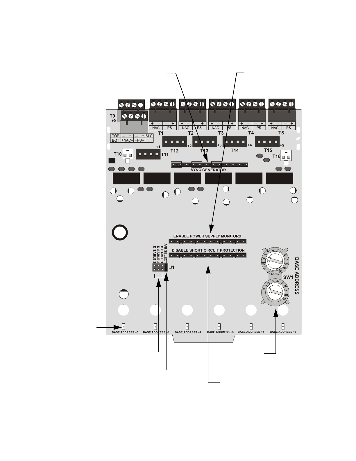
Control Modules CMF-300-6 Installation
CMF-300-6.wmf
Synchronization Generator -
Not Supported. DO NOT
remove shunts.
Power Supply Monitors -
Not Supported. DO NOT
remove shunts.
Disable Address -
Place shunt onto required pins.
Select
Style Y (Class B) or
Style Z (Class A) -
Remove shunt for Style Z (Class A).
Short Circuit Protection - Remove
shunt from the corresponding pins to
enable. Shunt #1 for first address, #2
for second address, etc.
#1 #2 #3 #4 #5 #6
SLC Address
Set rotary switches to
address required.
Status Indicators
Green LEDs are
controlled by FACP to
indicate status of each
module address.
Figure 6.4 CMF-300-6 Control Module Settings
6.4.6 Features Not Supported
The “Synchronization” and “Power Supply Monitoring” features are not supported at this time.
6.4.7 Circuit Board Information
50 FireLite SLC Wiring Manual — P/N 51309:P4 9/17/2014
Page 51
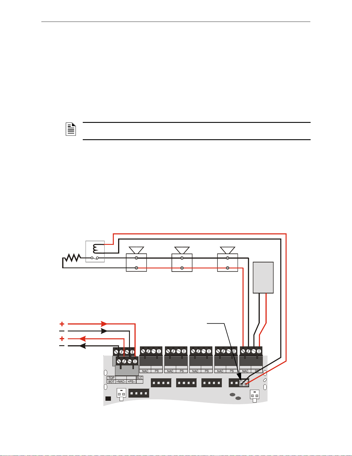
Wiring a CMF-300-6 Module Control Modules
+
+
–
–
– +
– +
– +
– +
– +
– +
– +
– +
– +
– +
– +
– +
T10
T1
+1
+2
+3
+4
+5
T0
+0
T2
T3
T4
T5
T11
T12
T13
T14
T15
T16
24 VDC notification appliances
NAC Out
24 VDC
nonresettable
power
SLC-nacY2.wmf
Power Supervision
Relay
(EOLR-1)
SLC
CMF-300-6
ELR 47K,
1/2-watt
Relay Connector Assembly
Figure 6.5 NFPA Style Y Notification Appliance Circuit
6.5 Wiring a CMF-300-6 Module
This section contains basic instructions and diagrams for wiring a Signaling Line Circuit with a
CMF-300-6 as a Notification Appliance Circuit (NAC).
For more detailed information on wiring a CMF-300-6 Control Module refer to the Installation
Instructions provided with the module. Included in these instructions are wiring diagrams concerning a single power supply being shared by multiple NACs and audio NAC configurations.
6.5.1 Wiring a Style Y NAC (Two-Wire)
A supervised and power-limited NFPA Style Y (Class B) NAC with a single power supply dedicated to a single NAC using a CMF-300-6 module. Polarized alarm notification appliances are
shown connected to the module in a two-wire configuration.
NOTE: Refer to the Device Compatibility Document for compatible notification appliances and
relays.
• See “Power Considerations” on page 68 for informat ion on monitoring 24 VDC power.
• Each module can control 2 amps of resistive load (on electronic devices) or 1 amp of inductive
load (on mechanical bells and horns).
• 24 VDC power must be provided from a UL listed power supply for fire protection use.
• A power supervision relay is required only on the last module of the power run.
• Do not T-tap or branch a Style Y circuit.
• Terminate the circuit across the last device using an End-of-Line Resistor 47K, 1/2-watt,
P/N SSD A2143-00 (ELR-47K in Canada).
• Do not loop wiring under the screw terminals of any notification appliance. To maintain supervision, break the wire run at each device.
FireLite SLC Wiring Manual — P/N 51309:P4 9/17/2014 51
Page 52
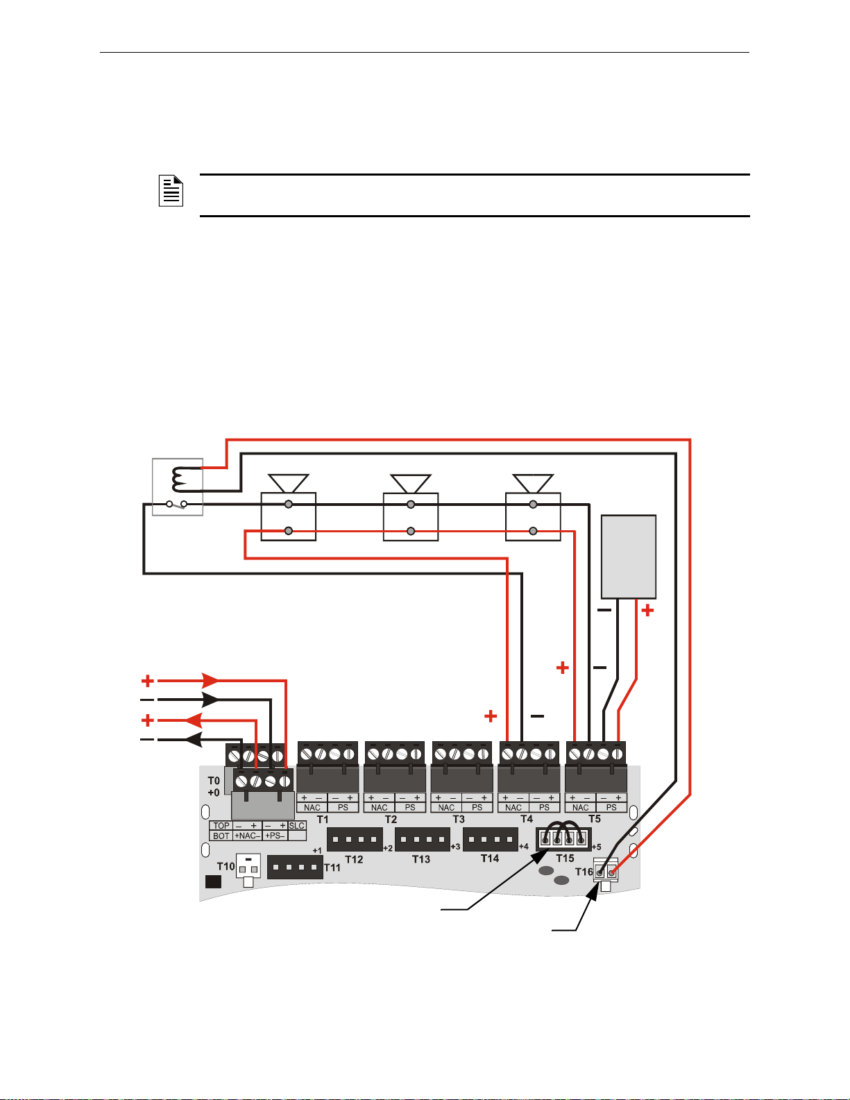
Control Modules Wiring a CMF-300-6 Module
Power Supervision
Relay
(EOLR-1)
24 VDC notification appliances
24 VDC
nonresettable
power
NAC
Out
CMF-300-6
NAC
Return
SLC
SLC-nacZ3.cwmf
Power Supply Jumper
Relay Connector Assembly
Figure 6.6 NFPA Style Z Notification Appliance Circuit
6.5.2 Wiring a Style Z NAC (Four-Wire)
A supervised and power-limited NFPA Style Z (Class A) NAC with a single power supply dedicated to a single NAC using a CMF-300-6 module. Polarized alarm notification appliances are
shown connected to the module in a four-wire configuration.
NOTE: Refer to the Device Compatibility Document for compatible notification appliances and
relays.
• See “Power Considerations” on page 68 for informat ion on monitoring 24 VDC power.
• Each module can control 2 amps of resistive load (on electronic devices) or 1 amp of inductive
load (on mechanical bells and horns).
• 24 VDC power must be provided from a UL listed power supply for fire protection use.
• A power supervision relay is required only on the last module of the power run.
• Do not T-tap or branch a Style Z circuit.
• Do not loop wiring under the screw terminals of any notification appliance. To maintain
supervision, break the wire run at each device.
52 FireLite SLC Wiring Manual — P/N 51309:P4 9/17/2014
Page 53
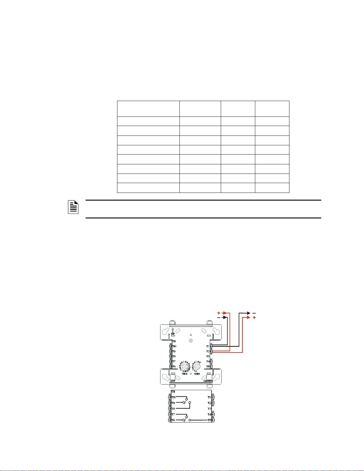
7.1 Description
SLC
SLC-frmCtpH.wmf
CRF-300
NO
C
NC
NO
C
NC
Figure 7.1 CRF-300 Wiring Connections
The CRF-300 and the CRF-300-6 modules are addressable modules that provides Form-C relay
contacts.
Ratings for the relay contacts on the module are:
Section 7: Relay Modules
Load Description Application
Resistive Non-Coded 30 VDC 3.0 A
Resistive Coded 30 VDC 2.0 A
Resistive Non-Coded 110 VDC 0.9 A
Resistive Non-Coded 125 VAC 0.9 A
Inductive (L/R = 5ms) Coded 30 VDC 0.5 A
Inductive (L/R = 2ms) Coded 30 VDC 1.0 A
Inductive (PF = 0.35) Non-Coded 70.7 VAC 0.7 A
Inductive (PF = 0.35) Non-Coded 125 VAC 0.5 A
NOTE: For more information on the module specifications refer to the Installation Instructions
provided with these devices.
7.2 CRF-300 Installation & Wiring
7.2.1 Setting an SLC address for a CRF-300 Module
Each module is factory preset with an address of “00”. To set an SLC address, refer to “Setting an
SLC address for a Single Point Module” on page 34.
Maximum
Voltage
Current
Rating
7.2.2 Wiring a CRF-300 Module (Form-C Relay)
The figure below shows a CRF-300 module wired to the Control Panel:
FireLite SLC Wiring Manual — P/N 51309:P4 9/17/2014 53
Page 54
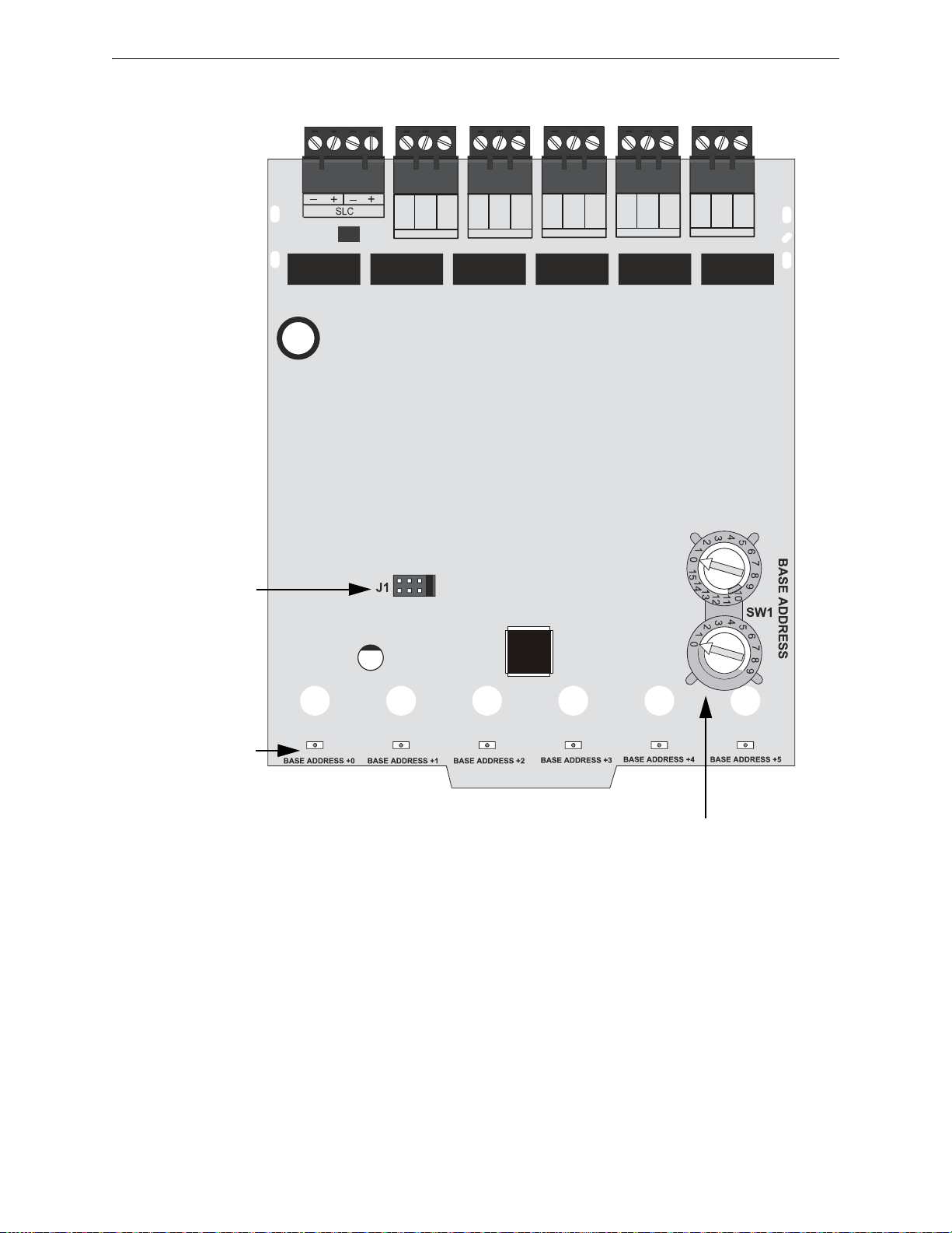
Relay Modules CRF-300-6 Circuit Board Information
T102
ADDRESS
DISABLE
NONE
ONE
TWO
THREE
N.C.
N.O.
COMM
BASE ADDRESS +0
N.C.
N.O.
COMM
BASE ADDRESS +1
N.C.
N.O.
COMM
BASE ADDRESS +2
N.C.
N.O.
COMM
BASE ADDRESS +4
N.C.
N.O.
COMM
BASE ADDRESS +5
Disable Address
Place shunt onto
required pins.
SLC Address
Set rotary switches to
address required.
Status Indicators
Green LEDs are
controlled by FACP to
indicate status of each
module address.
Figure 7.2 CRF-300-6 Control Relay Module
crf-300-6.wmf
7.3 CRF-300-6 Circuit Board Information
7.4 CRF-300-6 Installation & Wiring
7.4.1 Cabinet Installation
This type of module is contained in either a BB-2 or BB-6 cabinet. The BB-2 can accommodate up
to 2 modules and the BB-6, which requires the CH-6 chassis, can accommodate up to 6 modules.
See the Installation Instructions provided with module for proper installation into cabinet.
54 FireLite SLC Wiring Manual — P/N 51309:P4 9/17/2014
Page 55
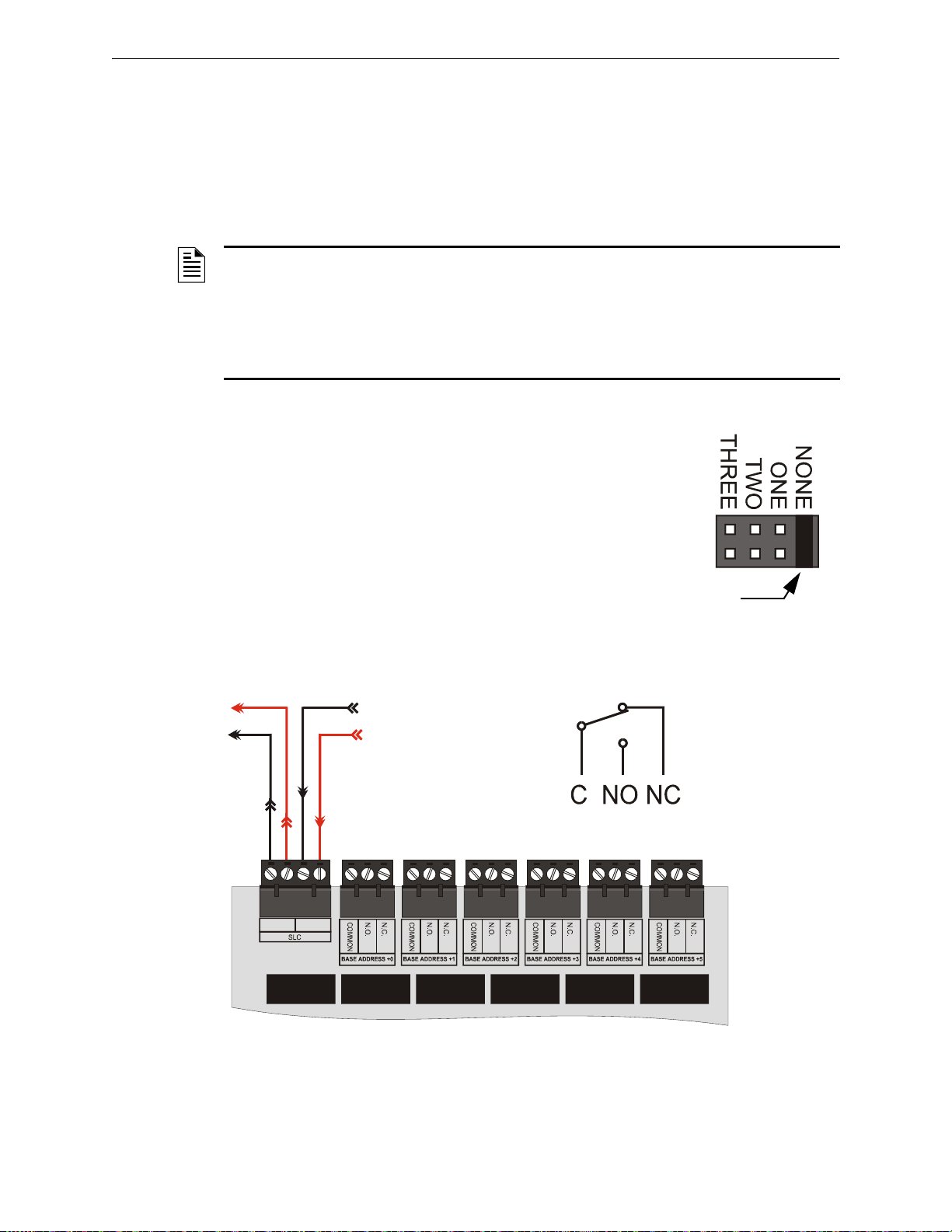
CRF-300-6 Installation & Wiring Relay Modules
J1
Shunt Storage
Location
SLC-disable2.wmf
+
–
+
–
– +
– +
SLC In
Relay Connections
SLC-fmC1.wmf
CRF-300-6
SLC Out
Figure 7.3 CRF-300-6 Wiring Conn e ct io n s
7.4.2 Setting an SLC address for a CRF-300-6 Module
Each CRF-300-6 module can be set to one of 154 base addresses (01-154). The remaining module
points are automatically assigned to the next five higher SLC addresses. For example, if the base
address is set to 28, the next five module points will be addressed to 29, 30, 31, 32 and 33.
DO NOT set the lowest address above 154 (45 for the MS-9050UD, 94 for the MS-9200, MS9200UD, and MS-9200UDLS), as the other module points will be assigned to nonexistent
addresses.
NOTE: The MS-9050UD can support addresses 01 - 50. The MS-9200, MS-9200UD, and MS9200UDLS can support module addresses of 01 - 99. The MS-9600, MS-9600LS, and MS9600UDLS can support module addresses 01 - 159. To set an SLC address, use a common
screwdriver to adjust the rotary switches on the module to the desired address. See Figure 6.4 on
page 50.
For use with an MS-9600, MS-9600LS, MS-9600LSC, an d MS-9600UDLS, remove the stop on
the upper rotary switch.
7.4.3 Disabling Unused Module Addresses
A shunt is provided on the circuit board to disable a maximum of three (3)
unused module addresses. If two module addresses are disabled, the lowest four addresses will be functional, while the highest two will be disabled. For example, if the shunt is placed on ‘TWO’ and the base address
is set to 28, the module addresses will be assigned to 28, 29, 30 and 31.
To disable addresses, remove the shunt from it’s storage location and
securely place it onto the desired set of pins. See illustration.
7.4.4 Wiring a CRF-300-6 Module (Form-C Relay)
The figure below shows a CRF-300-6 module wired to the Control Panel.
FireLite SLC Wiring Manual — P/N 51309:P4 9/17/2014 55
Page 56

Notes
56 FireLite SLC Wiring Manual — P/N 51309:P4 9/17/2014
Page 57

Section 8: Multiple Input/Output Modules
8.1 Description
The CDRM-300 is an addressable module that functions as two individual relay control modules
(two isolated sets of Form-C relay contacts) and two Class B monitor modul es.
Ratings for the relay contacts on the module are:
Load Description Application
Inductive (PF = 0.35) Non-Coded 25 VAC 2.0 A
Resistive Non-Coded 30 VDC 3.0 A
Resistive Coded 30 VDC 2.0 A
Inductive (L/R = 20ms) Non-Coded 30 VDC 0.46 A
Inductive (PF = 0.35) Non-Coded 70.7 VAC 0.7 A
Resistive Non-Coded 125 VDC 0.9 A
Inductive (PF = 0.75) Non-Coded 125 VAC 0.5 A
Inductive (PF = 0.35) Non-Coded 125 VAC 0.3 A
NOTE: For more information on the module specifications refer to the Installation Instructions
provided with these devices.
Maximum
Voltage
8.2 CDRM-300 Installation & Wiring
8.2.1 Setting an SLC address for a CDRM-300 Module
Each module is factory preset with an address of “00”. To set an SLC address, use a screwdriver to
adjust the rotary switches on the module to the desired address. Each module can use up to four (4)
addresses. The base address selected via the rotary address switches will be assigned to relay output
#1 from 00 to 156. The module will automatically assign the next three addresses as appropriate to
monitored input #1, relay output #2, and monitored input #2.
Current
Rating
FireLite SLC Wiring Manual — P/N 51309:P4 9/17/20149/17/2014 57
Page 58
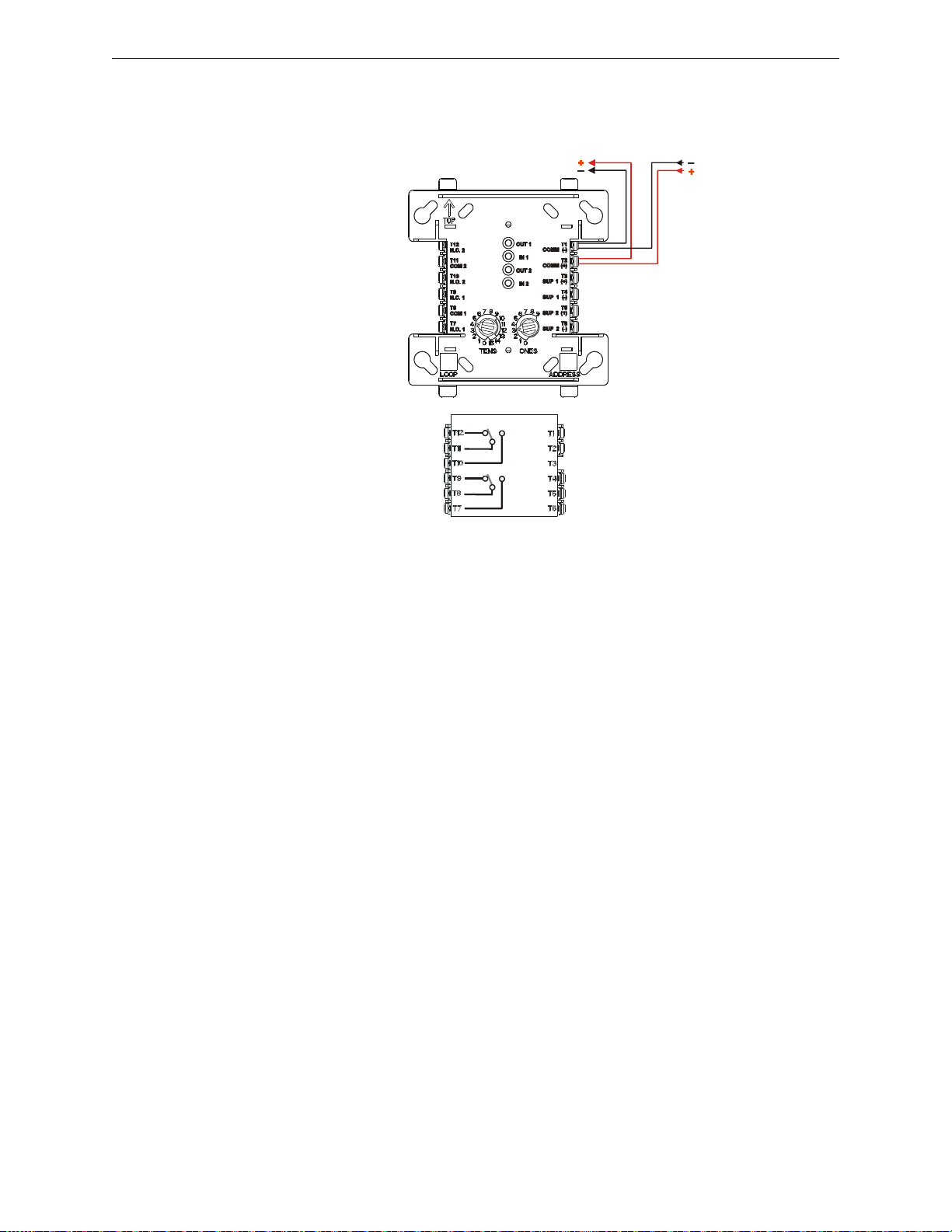
Multiple Input/Output Modules CDRM-300 Installation & Wiring
SLC
fdrm-1.wmf
CDRM-300
IDC 1 (+)
IDC 1 (-)
IDC 2 (+)
IDC 2 (-)
NC
C
NO
NC
C
NO
Figure 8.1 CDRM-300 Wiring Connections
Normally Closed
Common
Normally Open
Normally Closed
Common
Normally Open
8.2.2 Wiring a CDRM-300 Module (Form-C Relay)
The figure below shows a CDRM-300 module wired to the Control Panel.
58 FireLite SLC Wiring Manual — P/N 51309:P4 9/17/20149/17/2014
Page 59

Section 9: Intelligent Detector Bases and Wireless
Gateway
9.1 Description
The following bases provide connection between the SLC and these detector heads:
• AD350 and AD355 Multi-criteria Photoelectric Smoke Detector
• CP350 and CP355 Ionization Smoke Detector
• H350, H350R, H355, H355R and H355HT Thermal Detector
• SD350, SD350T, SD355 and SD355T Photoelectric Smoke Detector
The B501 and B210LP bases are standard plug-in detector bases.
The B501BH, B501BHT, B501BH-2, B501BHT-2, B200SR, and B200SR-LF Sounder Detector
Bases include a horn that will sound when the sensor’s visible LEDs are latched on for approximately 10 seconds.
On the MS-9200 Control Panel, the sounder will activate when the sensor ’s visible LEDs are
latched on for approximately 10 seconds (Alarm Verification does not delay sounder).
If the MS-9600, MS-9600LS, MS-9600UDLS, MS-9200UD, MS-9200UDLS, or MS-9050UD
Control Panel is set with Alarm Verification ON, the sounder will activate at the end of the
verification cycle, providing an alarm is verified, approximately 10 seconds after the sensor’s
LEDs are latched on. If Alarm Verification is OFF , the sounder will activate when the s ensor’s
visible LEDs are latched on for approximately 10 seconds.
The B224RB Relay Detector Base includes Form-C latching relay contacts for the control of an
auxiliary function. The relay operates 12 seconds (nominally) after activation of the sensor head
remote annunciator output.
The B224BI Isolator Detector Base prevents an entire communications loop from being disabled
when a short circuit occurs.
The W-GATE Wireless Gateway acts as a bridge between a group of wireless fire devices and a
LiteSpeed SLC loop on the MS-9200UDLS. The gateway can be powered by the SLC loop or by a
regulated, external UL-listed, 24VDC power supply. See Section 9.7.
NOTE: When using a Wireless Gateway on the SLC loop, the panel cannot have ANY modules
(wired or wireless) in the address range from 140 to 159.
For details about the wireless network and its devices, see the SWIFT™ Smart Wireless Integrated
Fire Technology Instruction Manual #LS 10036-000FL-E.
9.2 Setting the Detector Address
Each intelligent detector is factory preset with an address of “00.” To set an SLC address, use a
common screwdriver to adjust the rotary switches on the detector to the desired address (see “Setting an SLC address for a Single Point Module” on page 34). When finished, mark the address in
the place provided on the base and the detector.
FireLite SLC Wiring Manual — P/N 51309:P4 9/17/2014 59
Page 60
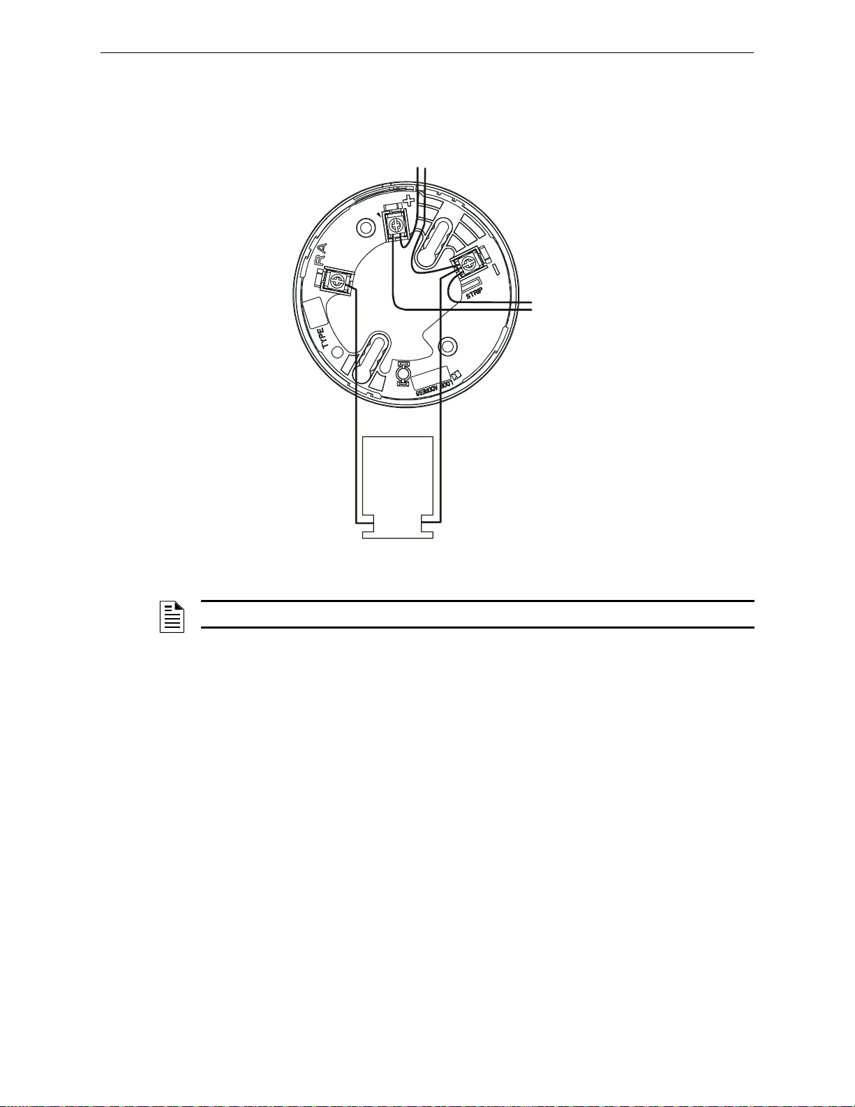
Intelligent Detector Bases and Wireless Gateway Wiring a Detector Base
+ –
+ –
–
+
SLC-B5012wire.wmf
RA100Z /
RA400Z
Remote LED
Annunciator
(Optional)
To Next Device
on SLC
From Control Panel SLC
Figure 9.1 Wiring a B210LP or B501 Detector Base
9.3 Wiring a Detector Base
T ypical wiring of a detector base (B501 shown) connected to an SLC is shown in the figure below.
An optional RA100Z/RA400Z Remote LED Annunciator is shown connected to the detector.
NOTE: The B210LP base wiring is identical to the B501. B501 is the flangeless model.
60 FireLite SLC Wiring Manual — P/N 51309:P4 9/17/2014
Page 61
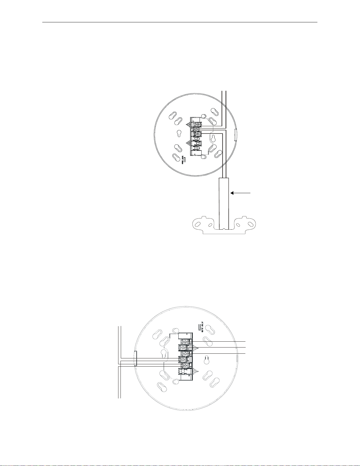
Wiring an Isolator Base Intelligent Detector Bases and Wireless Gateway
– +
– +
SLC Out
SLC In
Conduit
I300 Isolator Module
s
lc
-
2
2
4
b
i2
w
ir
e
.
w
m
f
Figure 9.2 Wiring of a B224BI Isolator Base Mounting Plate
Note: The “grid” pattern on the
redesigned B224BI mounting
plate has been removed for
illustration purposes only.
+ -
+ -
s
lc
-
b
2
2
4
r
b
2
w
ir
e
.
w
m
f
Figure 9.3 Wiring of a B224RB Relay Base Mounting Plate
To next device
on SLC
SLC
Normally Closed
Common
Normally Open
Note: The “grid” pattern on the
redesigned B224RB mounting
plate has been removed for
illustration purposes only.
9.4 Wiring an Isolator Base
The B224BI Isolator Base will isolate its detector from short circuits that occur on the SLC connected at terminals 2 and 3. It will not isolate its installed detector from short circuits that occur on
the SLC connected at terminals 1 and 2. In Style 7 applications, the loss of a single detector during
a short circuit is not acceptable, and an isolator module must be installed as shown in the figure
below.
9.5 Wiring a Relay Base
FireLite SLC Wiring Manual — P/N 51309:P4 9/17/2014 61
Figure 9.3 shows typical wiring of a B224RB plug-in relay detector base co nnect ed to an SLC.
Page 62
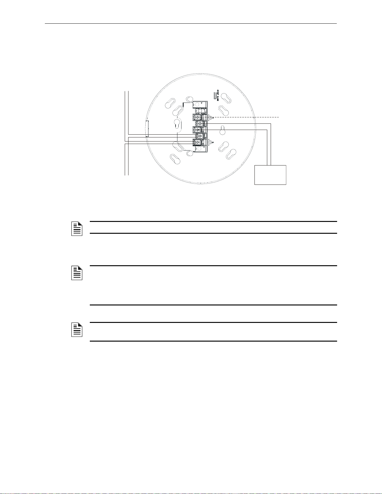
Intelligent Detector Bases and Wireless Gateway Wiring a Sounder Base
+ -
+ -
+ -
s
lc
-
b
2
0
0
s
r
w
ir
e
.
w
m
f
Figure 9.4 Wiring of a B200SR/B200SR-LF Sounder Base
To next device
on SLC
SLC
Note: The “grid” pattern on the
sounder base has been removed
for illustration purposes only.
UL-Listed
24V Power
Supply
Optional Sounder
Interconnect
9.6 Wiring a Sounder Base
Figure 9.4 shows typical wiring of the B200SR or B200SR-LF Sounder Base.
9.7 Wiring the W-GATE
NOTE: For more detailed wiring on the sounder base, refer to the device’s installation instructions.
NOTE: The W-GATE, as part of the wireless network, has been tested for compliance with the
Federal Communications Commission (FCC) requirements of the United States Government. It
has not been evaluated for use outside the USA. Use of this system outside the USA is subject to
local laws and rules to which this product may not conform. It is the sole responsibility of the user
to determine if this product may be legally used outside the USA.
NOTE: It is recommended to use the same wire gauge if there are multiple connections to the
same terminal.
9.7.1 SLC Connections
The W-GATE Wireless Gateway acts as a bridge between a group of wireless fire devices and a
LiteSpeed SLC loop on the MS-9200UDLS. It is powered by the SLC loop or by a regulated,
external 24VDC UL-listed power supply. Available wireless devices include a photo detector, a
photo/heat detector, a fixed-temperature heat detector, a rate-of-rise heat detector, and a monitor
module. For details about wireless devices, system setup, and operation, see the SWIFT™ Smart
Wireless Integrated Fire Technology Instruction Manual.
62 FireLite SLC Wiring Manual — P/N 51309:P4 9/17/2014
Page 63
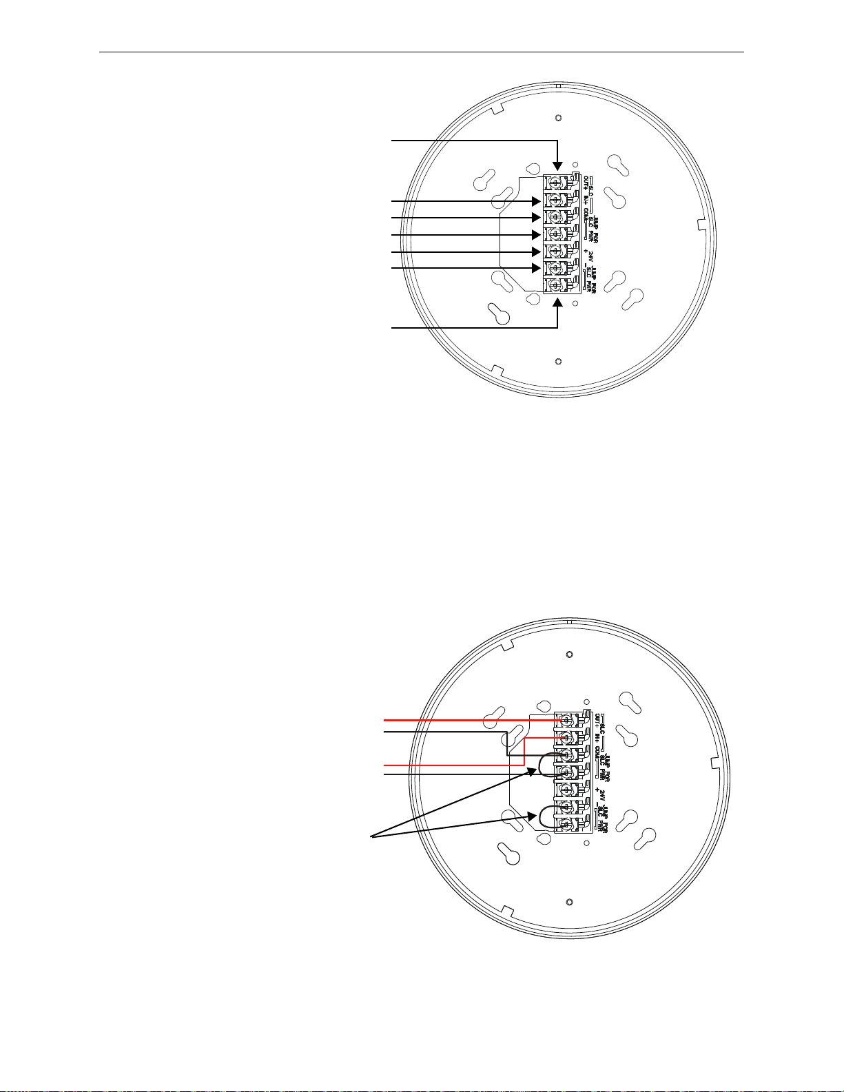
Wiring the W-GATE Intelligent Detector Bases and Wireless Gateway
A7- SLC OUT+
A6- SLC IN+
A5- SLC- (Common)
A4- SLC Power Select 2
A3- Power +24VDC
A2- Power Ground
A1- SLC Power Select 1
Figure 9.5 W-GATE Mounting Plate - Terminal Layout
2
.
4
.
w
m
f
+
+
-
-
SLC in from FACP/device
SLC out to next device (Class B)
or SLC return to FACP (Class A)
Jumpers
2
.
5
.
w
m
f
Figure 9.6 W-GATE Powered by the SLC
9.7.2 W-GATE Powered by the SLC
The W-GATE provides isolation of short circuits on the SLC in Class A (Style 6) installations. SLC
connections are power-limited by the panel. An interruption in the SLC that causes a loss of power
at the W-GATE for more than 100ms may result in a trouble condition and loss of fire protection
provided by the wireless devices for approximately 15 minutes. Use of a regulated, external
+24VDC power source (not SLC power) is recommended for installations that require fire protection in the presence of short circuits, including Class A applications and applications that use isolator modules. Figure 9.6 shows typical wiring of a Wireless Network Gateway connected to an SLC
when power is supplied by the SLC loop
FireLite SLC Wiring Manual — P/N 51309:P4 9/17/2014 63
Page 64
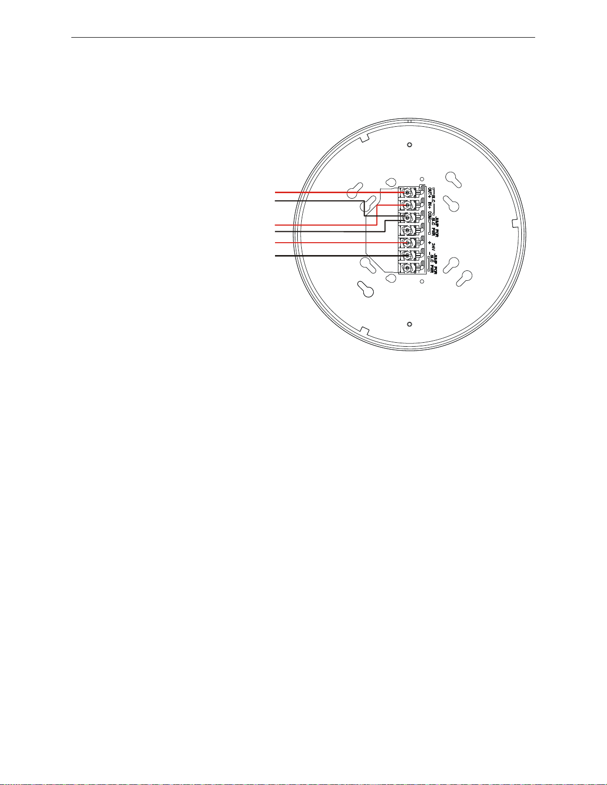
Intelligent Detector Bases and Wireless Gateway Wiring the W-GATE
+
+
-
-
+
-
2
.
6
.
w
m
f
Figure 9.7 W-GATE Powered by a Regulated, External Source
External 24VDC Power
SLC in from FACP/device
SLC out to next device (Class B)
or SLC return to FACP (Class A)
9.7.3 W-GATE Powered by a Regulated, External +24VDC Power Source
The FWSG provides isolation of short circuits of the SLC in Class A (Style 6) installations. SLC
connections are power-limited by the panel. +24VDC must be power-limited by the source..
64 FireLite SLC Wiring Manual — P/N 51309:P4 9/17/2014
Page 65

Section 10: Addressable Beam Detectors
10.1 Description
The BEAM355 and BEAM355S are intelligent, addressable projected beam smoke detectors,
designed for protecting open areas with high and sloping ceilings and wide-open areas, where spot
type smoke detectors are difficult to install and maintain. The BEAM355S has an integral sensitiv-
ity test feature that consists of a test filter attached to a servomotor inside the detector optics.
NOTE: This section provides basic wiring and addressing information. For critical information
on device installation, operation and alignment, refer to the Installation Instructions provided with
these devices.
10.2 Installation and Wiring
10.2.1 Setting an SLC Address for a Beam Detector
Each beam detector is factory preset with an address of “00.” To set an SLC address, use a common screwdriver to adjust the address rotary code switches on the detector to the desired address
(refer to 5.2.1“Setting an SLC address for a Single Point Module” on page 34).
FireLite SLC Wiring Manual — P/N 51309:P4 9/17/2014 65
Page 66
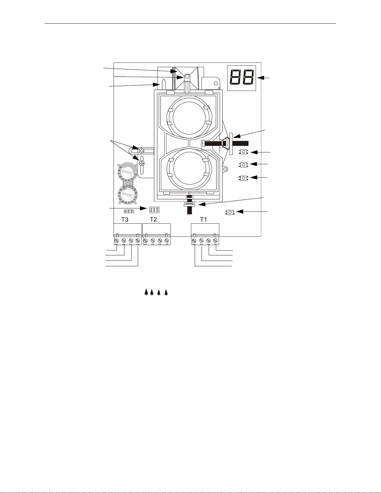
Addressable Beam Detectors Installation and Wiring
Figure 10.1 Beam Detector Terminal Block Wiring
SLC (-) to next device
SLC (+) to next device
SLC (-) from panel or previous device
SLC (+) from panel or previous device
Test Option (-)
Test Option (+)
not used
not used
Reset Input
Test Input
Remote Alarm Out
Aux (-)
Alignment Switch
Sensitivity Switch
Test Switch
Reset Switch
Style 7 Isolator Shunts
RTS151/KEY& RTS-451/KEY
Connections
Digital Signal
Strength Readout
ONES TENS
ADDRESSING
CODE
SWITCHES
Alignment Mirror
Alignment Position
Indicator
Optics Lock-down
Screws
Alignment Gunsight
Horizontal Adjustment
Vertical Adjustment
10.2.2 Wiring a Beam Detector
Typical wiring of a beam detector connected to an SLC is illustrated in the figure below.
66 FireLite SLC Wiring Manual — P/N 51309:P4 9/17/2014
Page 67
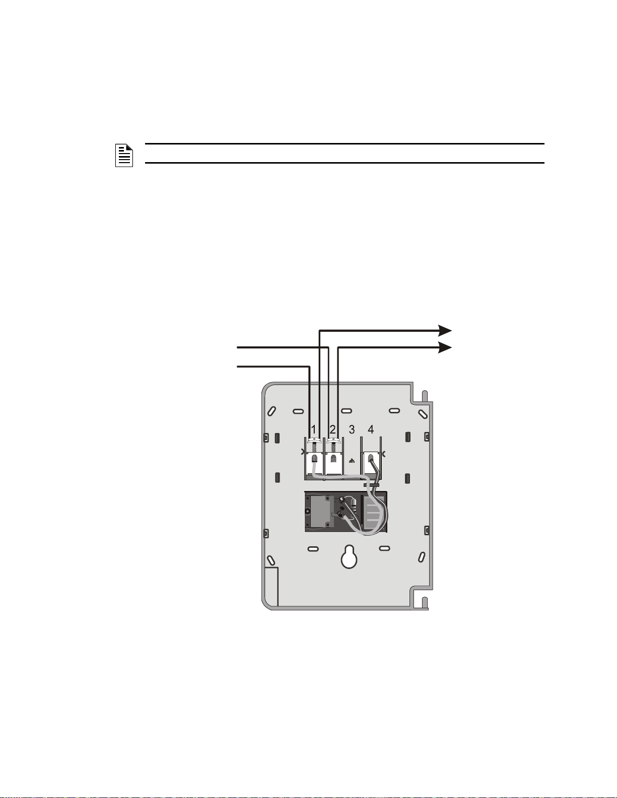
Section 11: Addressable Manual Pull Station
+
–
–
+
US PAT 4440991
SLC
To next device
on SLC
S
L
C
-
b
g
1
2
lx
2
.
w
m
f
Figure 11.1 Wiring of a BG-12LX Pull Station to an SLC
11.1 Description
The BG-12LX is an addressable manual pull station with a key-lock reset feature.
NOTE: For more information refer to the Installation Instructions provided with this device.
11.2 Installation
11.2.1 Setting an SLC address
Each unit is factory preset with an address of “00.” To set an SLC address refer to “Setting an SLC
address for a Single Point Module” on page 34.
11.2.2 Wiring a Manual Pull Station
Figure 11.1 shows typical wiring for a BG-12LX Manual Pull Station to an SLC:
FireLite SLC Wiring Manual — P/N 51309:P4 9/17/2014 67
Page 68

Appendix A: Power Considerations
A.1 Supplying Power to 24 VDC Detectors and NACs
A.1.1 Resistance and Size
To determine the minimum resistance that can be tolerated in supplying power to 24 VDC 4-wire
devices and NACs, use the calculation below. Use this resistance to select the proper gauge wire for
the power run from the manufacturers specifications for the desired wire.
For Four-Wire Detectors:
(Vms - Vom)
Rmax =
(N)(Is) + (Na)(Ia) + (Ir)
For NACs:
(Vms - Vom)
Rmax =
(Nb)(Ib)
Where:
Rmax = maximum resistance of the 24 VDC wires
Vms = minimum supply voltage
Vom = minimum operating voltage of the detector or end-of-line relay, whichever is greater, in volts
N = total number of detectors on the 24 VDC supply circuit
Is = detector current in standby
Na = number of detectors on the 24 VDC power circuit which must function at the same time in alarm
Ia = detector current in alarm
Ir = end-of-line relay current
Nb = number of Notification Appliance Devices
Ib = Notification Appliance current when activated
NOTE: This simplified equation assumes that the devices are at the end of a long wire run.
The minimum supply voltages produced by Fire•Lite power supplies are listed belo w:
FACP Vms Power Supply Vms
MS-9200 16.0 FCPS-24F 19.1
MS-9600 16.0 FCPS-24FS6/FCPS-24FS8 19.1
MS-9200UD/MS-9200UDLS 19.05
MS-9050UD 18.75
Table A.1 Minimum Supply Voltage
68 FireLite SLC Wiring Manual — P/N 51309:P4 9/17/2014
Page 69
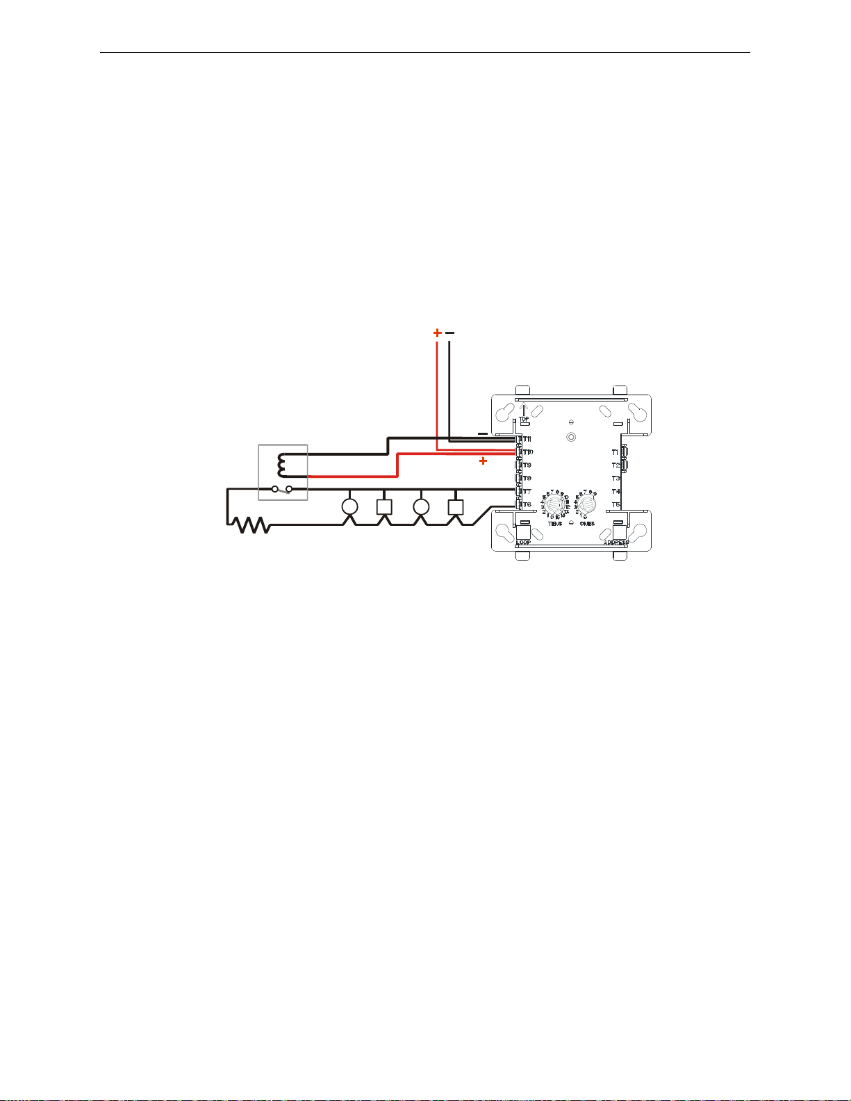
Supervising 24 VDC Power Power Considerations
S
L
C
-
p
s
r
t
p
H
.
c
d
r
24 VDC Power from
Control Panel or
Power Supply
Power Supervision
Relay
(EOLR-1)
Supervised NAC
ELR
47K
Last device on the SLC loop
Figure A.1 Supervised 24 VDC Circuit
A.2 Supervising 24 VDC Power
Power used to supply 24 VDC detectors, notification appliances (using the CMF-300), and two
wire detectors (using the MMF-302) can be supervised with a power supervision relay. This relay,
energized by the 24 VDC power itself, is installed at the end of each respective power run and
wired in-line with the supervised circuit of any intelligent module.
24 VDC power must be provided from a UL-listed power supply for fire protection use.
When power is removed from the relay, the normally closed contacts open the supervised circuit,
generating a trouble condition. Therefore, the relay needs to be installed at the end of the supervised circuit, so it will not disrupt the operating capability of all the devices on that circuit. The
relay can be installed in-line with any leg (+ or –) of the supervised NAC circuit, either a Style B
(Class B) or a Style D (Class A) circuit.
The drawing below illustrates this concept.
FireLite SLC Wiring Manual — P/N 51309:P4 9/17/2014 69
Page 70
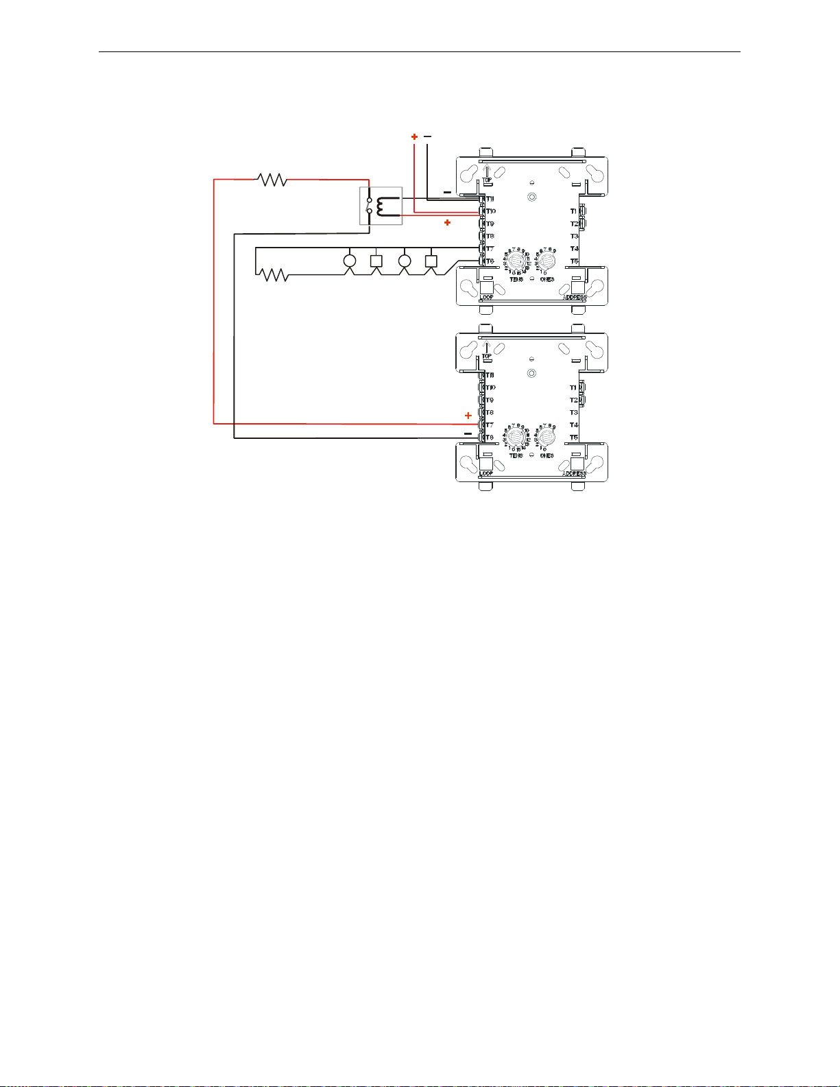
Power Considerations Supervising 24 VDC Power
CMF-300
MMF-300
Power Supervision
Relay
(EOLR-1)
Supervised NAC
ELR 47K
24 VDC Power from
Control Panel or Power Supply
S
L
C
-
p
s
r
-
2
a
d
d
r
e
s
s
t
p
H
.
w
m
f
ELR 47K
Figure A.2 Alternate: 2-Address Method of Supervising a 24 VDC Circuit
An alternate method is shown below.
70 FireLite SLC Wiring Manual — P/N 51309:P4 9/17/2014
Page 71
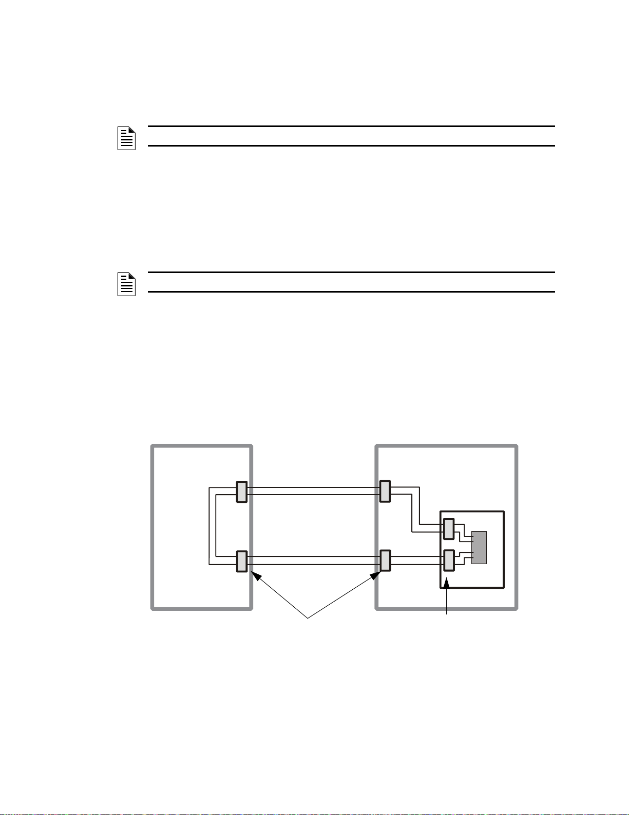
Appendix B: Surge Suppression
Primary devices meet
NEC Requirements
Secondary devices meet
UL1459 (UL1950)
S
L
C
-
s
s
b
u
ild
1
.
w
m
f
Building #2
Building #1
P = Primary
S = Secondary
Surge Suppressor
FACP
P
P
P
P
S
S
B.1 Introduction
NOTE: Surge protection is not required in Canadian applications.
There are three (3) primary surge protectors that are approved for use with the MS-9200, MS9200UD, MS-9200UDLS, MS-9600, MS-9600LS, MS-9600UDLS, and MS-9050UD.
• DTK-2LVLP-F Diversified Technology Group, Inc. 1720 Starkey Rd. Largo, FL 33771
(727) 812-5000
• SLCP-30 EDCO 1805 N.E. 19th Ave. Ocala, FL 34470 (352) 732-3029
• PLP-42N Northern Technologies, Inc. 23123 E. Madison Ave. Liberty Lake, WA 99019
(800) 727-9119
NOTE: For detailed information, refer to the Installation Instructions supplied with the unit.
One primary surge protector must be used with each SLC wiring pair whenever SLC wiring runs
outside the building.
• Install primary protection only as shown in this document.
• Refer to NEC Article 800 and local building code requirements.
B.2 Installation
FireLite SLC Wiring Manual — P/N 51309:P4 9/17/2014 71
Additional primary surge suppressors may be added as required by the NEC. Add these additional
suppressors in series with the SLC wiring at the building entry/exit.
Wiring connected to the surge suppressor output must remain within the building while wiring connected to the surge suppressor input may be routed outside the building as shown below.
Mounting of the surge suppressor must be inside the FACP enclosure or in a separate enclosure
listed for fire protective signaling use.
• Locate on an available stud and secure with nut.
• Unit is connected in series with the SLC Loop to protect the Control Panel.
• Provide a common ground to eliminate the possibility of a differential in ground potentials.
Page 72
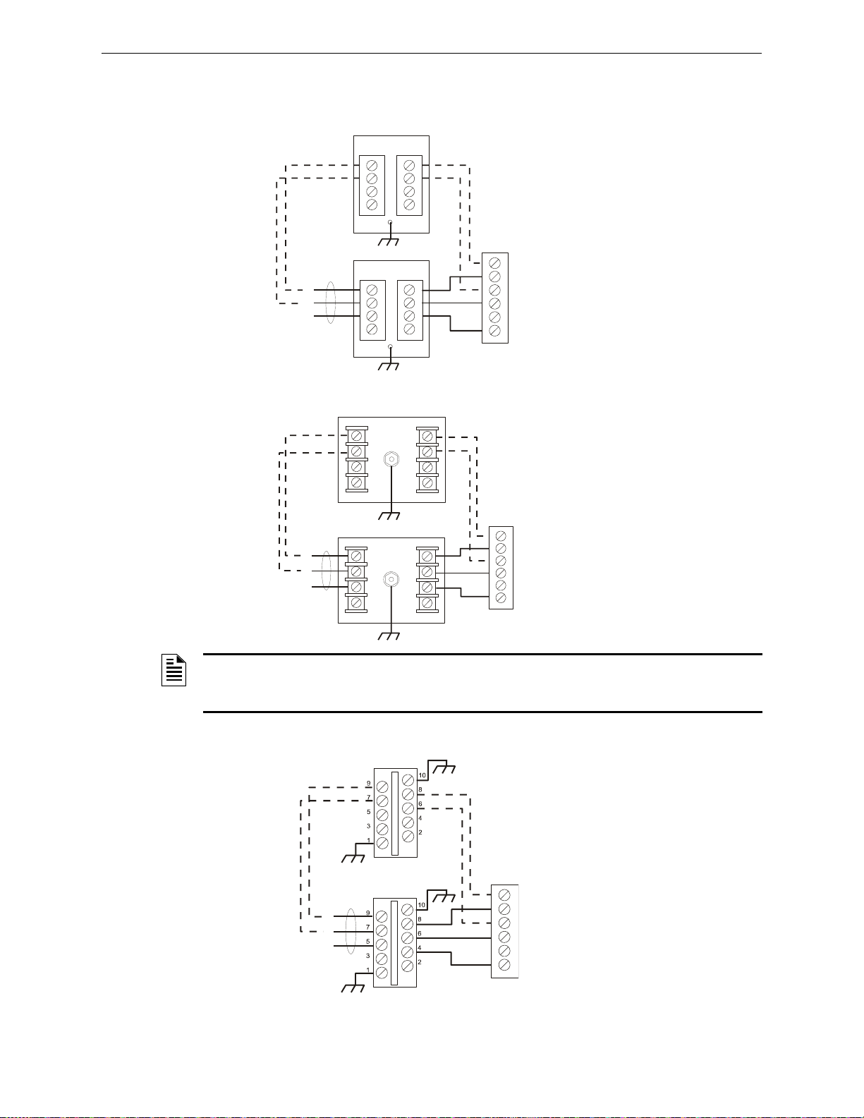
Surge Suppression Installation
–
+
SLC Loop
SLC Terminal Block
S
L
C
-
lv
lp
1
.
w
m
f
Optional Four-wire Return Loop
Style 6 (Class A)
2LVLP-F
2LVLP-F
IN OUT
IN OUT
ABA+
B+
A Shield
B Shield
–
+
INPUT
OUTPUT
L1 L2 L3 L4
L1 L2 L3 L4
GRND
INPUT
OUTPUT
L1 L2 L3 L4
L1 L2 L3 L4
GRND
S
L
C
-
p
lp
n
1
.
w
m
f
SLC Loop
SLC Terminal Block
Optional Four-wire Return Loop
Style 6 (Class A)
PLP-42N
PLP-42N
ABA+
B+
A Shield
B Shield
+
–
S
L
C
-
s
lc
p
1
.
w
m
f
SLC Terminal Block
SLC Loop
Optional Four-wire Return Loop
Style 6 (Class A)
2LCP-30
IN OUT
ABA+
B+
A Shield
B Shield
IN OUT
2LCP-30
B.2.1 Wiring Diagram for MS-9200
DTK-2LVLP-F Connections
PLP-42N Connections
NOTE: Use 12AWG (3.25mm2) to 18AWG (0.75mm2) wire with crimp-on connectors to connect
the unit’s ground terminal to equipment ground. Wire length must be minimized to provide best
protection.
SLCP-30 Connections
72 FireLite SLC Wiring Manual — P/N 51309:P4 9/17/2014
Page 73
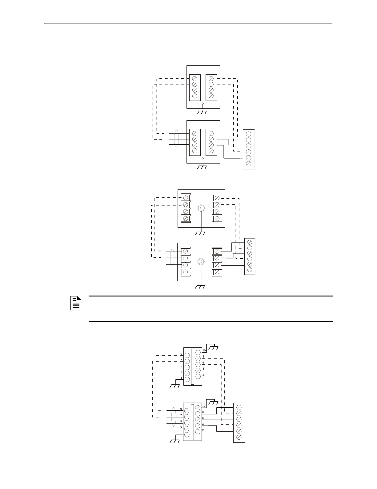
Installation Surge Suppression
–
+
SLC Loop
SLC Terminal Block
S
L
C
-
lv
lp
4
.
w
m
f
Optional 4-wire Return Loop
Style 6 (Class A)
2LVLP-F
2LVLP-F
IN OUT
IN OUT
B+
A+
BAA Shield
B Shield
–
+
INPUT
OUTPUT
L1 L2 L3 L4
L1 L2 L3 L4
GRND
INPUT
OUTPUT
L1 L2 L3 L4
L1 L2 L3 L4
GRND
S
L
C
-
p
lp
n
4
.
w
m
f
SLC Loop
SLC Terminal Block
Optional 4-wire Return Loop
Style 6 (Class A)
PLP-42N
PLP-42N
B+
A+
BAA Shield
B Shield
+
–
S
L
C
-
s
lc
p
4
.
w
m
f
SLC Terminal Block
SLC Loop
Optional 4-wire Return Loop
Style 6 (Class A)
2LCP-30
IN OUT
IN OUT
2LCP-30
B+
A+
BAA Shield
B Shield
B.2.2 Wiring Diagram for MS-9600, MS-9600LS, MS-9600UDLS,
MS-9200UD, MS-9200UDLS, and MS-9050UD
DTK-2LVLP-F Connections
PLP-42N Connections
NOTE: Use 12AWG (3.25mm2) to 18AWG (0.75mm2) wire with crimp-on connectors to connect
the unit’s ground terminal to equipment ground. Wire length must be minimized to provide best
protection.
SLCP-30 Connections
FireLite SLC Wiring Manual — P/N 51309:P4 9/17/2014 73
Page 74
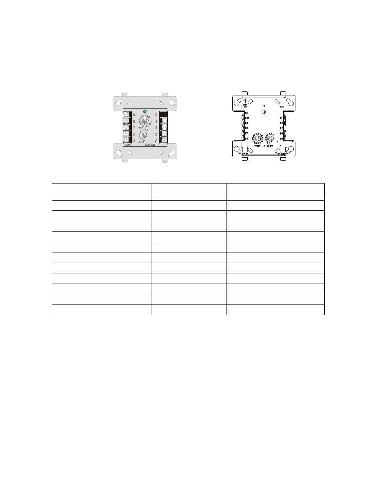
Appendix C: Terminal Conversion Charts for New &
Newer Module
(H-Type)
SLC SLC +
Common 2
Closed 2
Open 2
Common 1
Closed 1
Open 1
Legacy Module
(V-Type)
Common 2
Closed 2
Open 2
Common 1
Closed 1
Open 1
SLC SLC +
Legacy Devices
C.1 CRF-300
Legacy Module Terminal Number
(V-Type)
1SLC -1
2SLC +2
3Unused3
4 Normally Open (1) 5
5 Normally Closed (1) 6
6 Relay Common (1) 7
7 Normally Open (2) 8
8 Normally Closed (2) 9
9 Relay Common (2) 10
N/A Unused 4
N/A Unused 11
Table C.1 CRF-300Terminal Conversions
Terminal Function
Newer Module Terminal Number
(H-Type)
74 FireLite SLC Wiring Manual — P/N 51309:P4 9/17/2014
Page 75
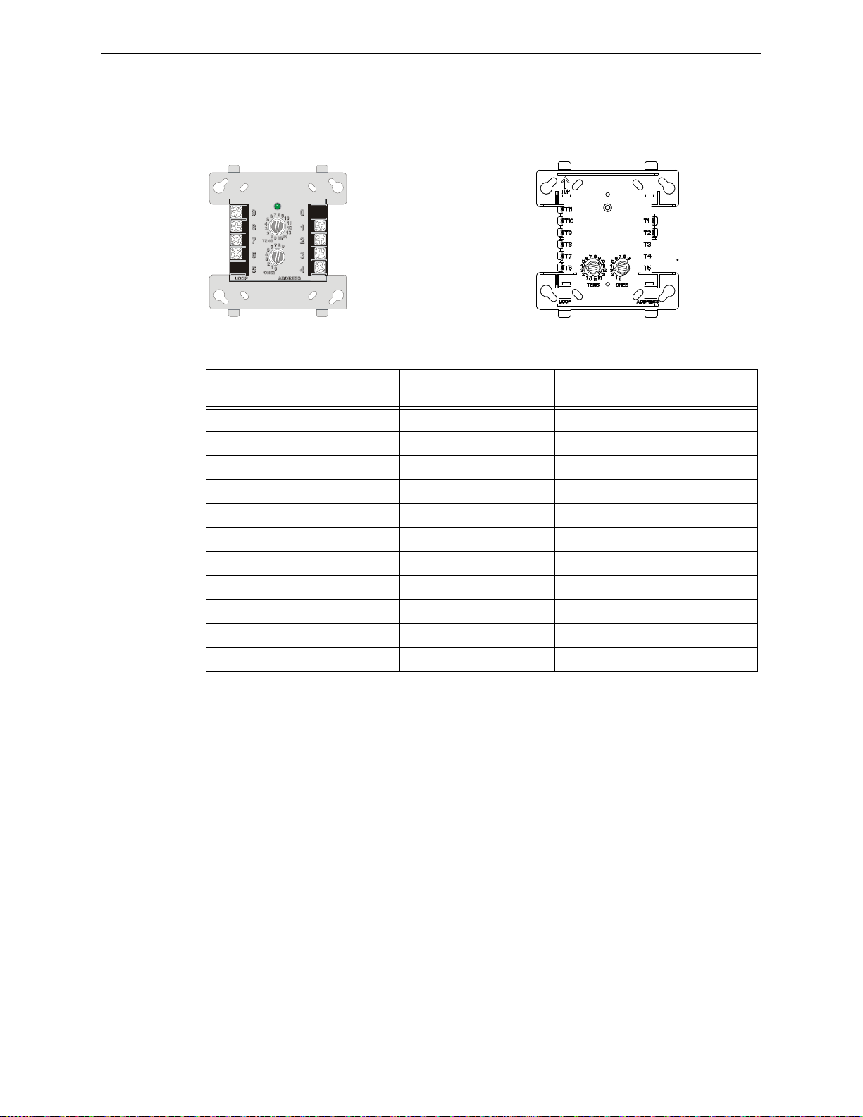
CMF-300 and MMF-302 Terminal Conversion Charts for New & Legacy Devices
Newer Module
(H-Type)
SLC SLC +
VDC -
VDC +
A-
A+
B/A +
B/A -
SLC SLC +
VDC VDC +
A-
A+
B/A +
B/A -
Legacy Module
(V-Type)
C.2 CMF-300 and MMF-302
All module polarities are shown in standby condition, which reflects the labels on the new m odules.
Legacy Module Terminal Number
(V-Type)
1SLC - 1
2SLC + 2
3VDC -11
4 VDC + 10
5Unused 5
6 Solenoid B/A - 6
7 Solenoid B/A + 7
8 Solenoid A + 8
9 Solenoid A - 9
N/A Unused 3
N/A Unused 4
Table C.2 CMF-300 and MMF-302 Terminal Conversions
Terminal Function
Newer Module Terminal Number
(H-Type)
FireLite SLC Wiring Manual — P/N 51309:P4 9/17/2014 75
Page 76
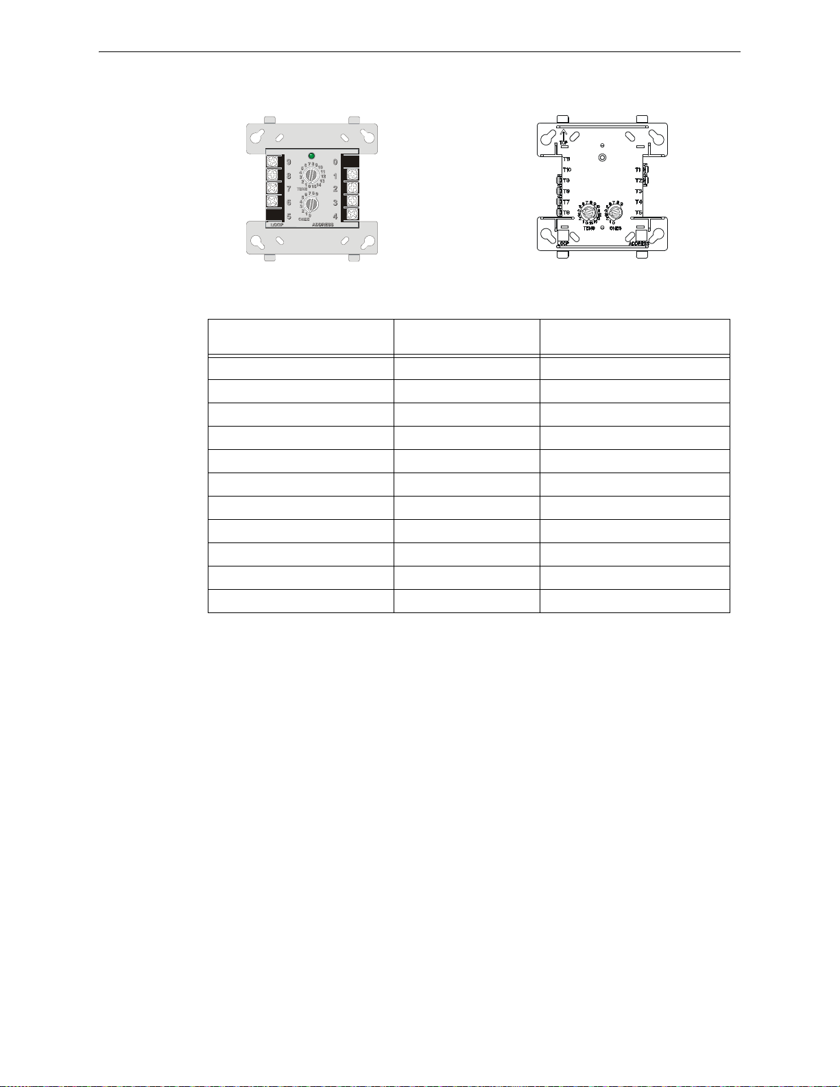
Terminal Conversion Charts for New & Legacy Devices MMF-300
Newer Module
(H-Type)
Class A Supervision Class A Supervision+
Class A/B Supervision +
Class A/B Supervision -
SLC SLC +
SLC SLC +
Class A Supervision -
Class A Supervision+
Class A/B Supervision +
Class A/B Supervision -
Legacy Module
(V-Type)
C.3 MMF-300
Legacy Module Terminal Number
(V-Type)
1SLC -1
2SLC +2
3 Unused 3
4 Unused 4
5 Unused 5
6 Class A/B Supervision - 6
7 Class A/B Supervision + 7
8 Class A Supervision + 8
9 Class A Supervision - 9
N/A Unused 10
N/A Unused 11
Table C.3 MMF-300 Terminal Conversions
Terminal Function
Newer Module Terminal Number
(H-Type)
76 FireLite SLC Wiring Manual — P/N 51309:P4 9/17/2014
Page 77
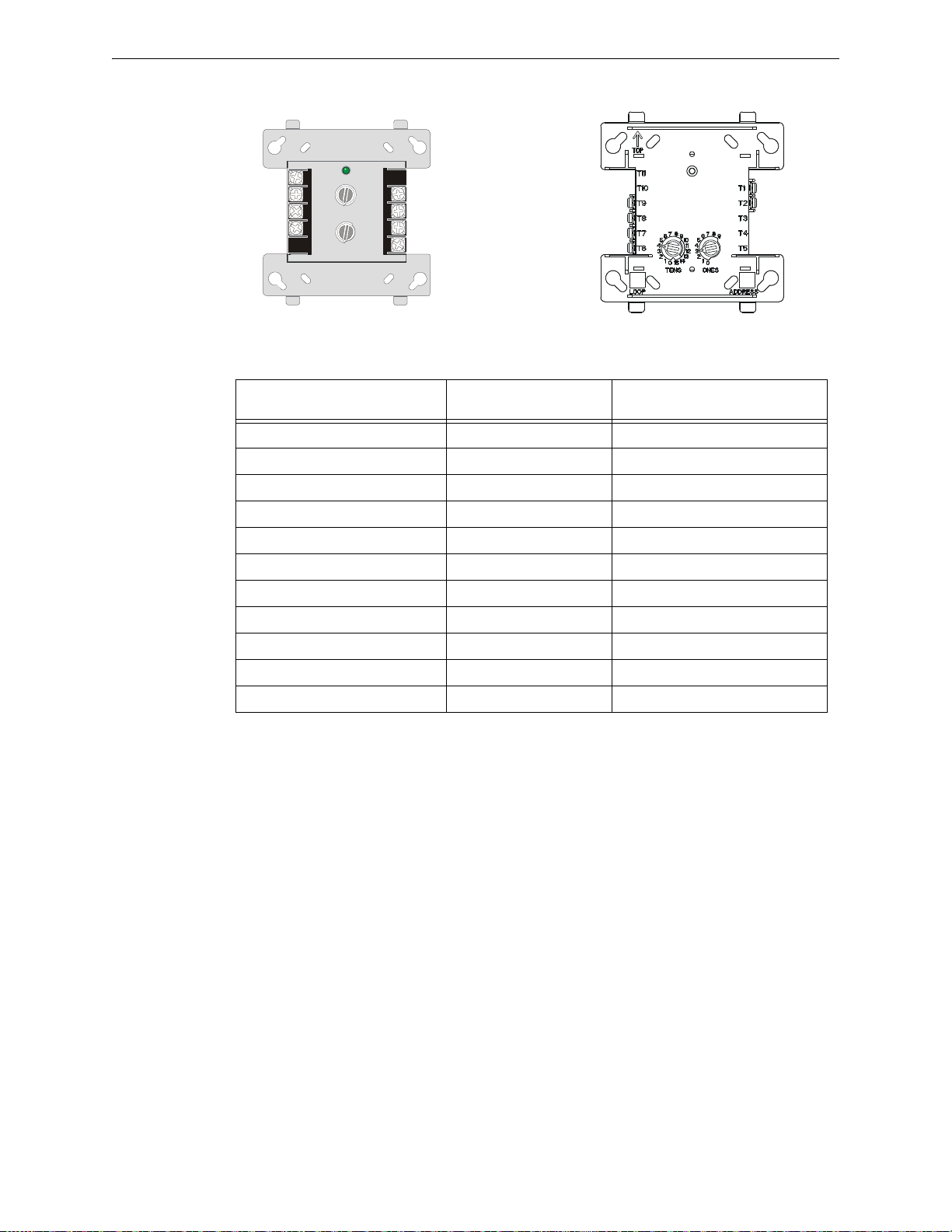
MDF-300 Terminal Conversion Charts for New & Legacy Devices
8
9
10
11
12
13
14
15
0
1
2
3
4
5
6
7
TENS
LOOP
LOOP
ADDRESS
ADDRESS
8
9
7
6
5
9
8
7
6
5
0
1
2
3
4
4
3
2
1
0
TENS
8
9
10
11
12
13
14
15
0
1
2
3
4
5
6
7
ONES
ONES
0
2
4
6
8
0
2
4
6
8
Newer Module
(H-Type)
Address +1 (H) -
Address +1 (H) +
Base Address (L) +
Base Address (L) -
SLC SLC +
SLC SLC +
Address +1 (H) -
Address +1 (H) +
Base Address (L) +
Base Address (L) -
Legacy Module
(V-Type)
C.4 MDF-300
Legacy Module Terminal Number
(V-Type)
1SLC -1
2SLC +2
3 Unused 3
4 Unused 4
5 Unused 5
6 Base Address (L) - 6
7 Base Address (L) + 7
8 Address +1 (H) + 8
9 Address +1 (H) - 9
N/A Unused 10
N/A Unused 11
Table C.4 MDF-300 Terminal Conversions
Terminal Function
Newer Module Terminal Number
(H-Type)
FireLite SLC Wiring Manual — P/N 51309:P4 9/17/2014 77
Page 78
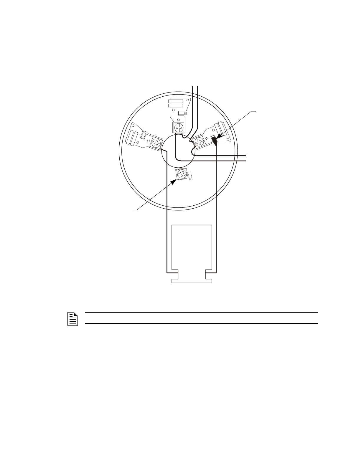
Appendix D: Intelligent Detector Base Layouts for
1(–)
2(+)
+ –
–
+
3
+ –
To next device
on SLC
SLC
S
L
C
-
B
5
0
1
w
ir
e
.
w
m
f
RA100Z/
RA400Z
Remote LED
Annunciator
(Optional)
B501 only: For connection of
cable shield
Use a female disconnect
to wire the
RA100Z/RA400Z (–) to
Terminal 1 (–).
Figure D.1 Wiring the Legacy B350LP or B501 Detector Base
Legacy Devices
D.1 B350LP or B501 Detector Base
NOTE: The B350LP base wiring is identical to the B501, except there is no shield terminal.
78 FireLite SLC Wiring Manual — P/N 51309:P4 9/17/2014
Page 79
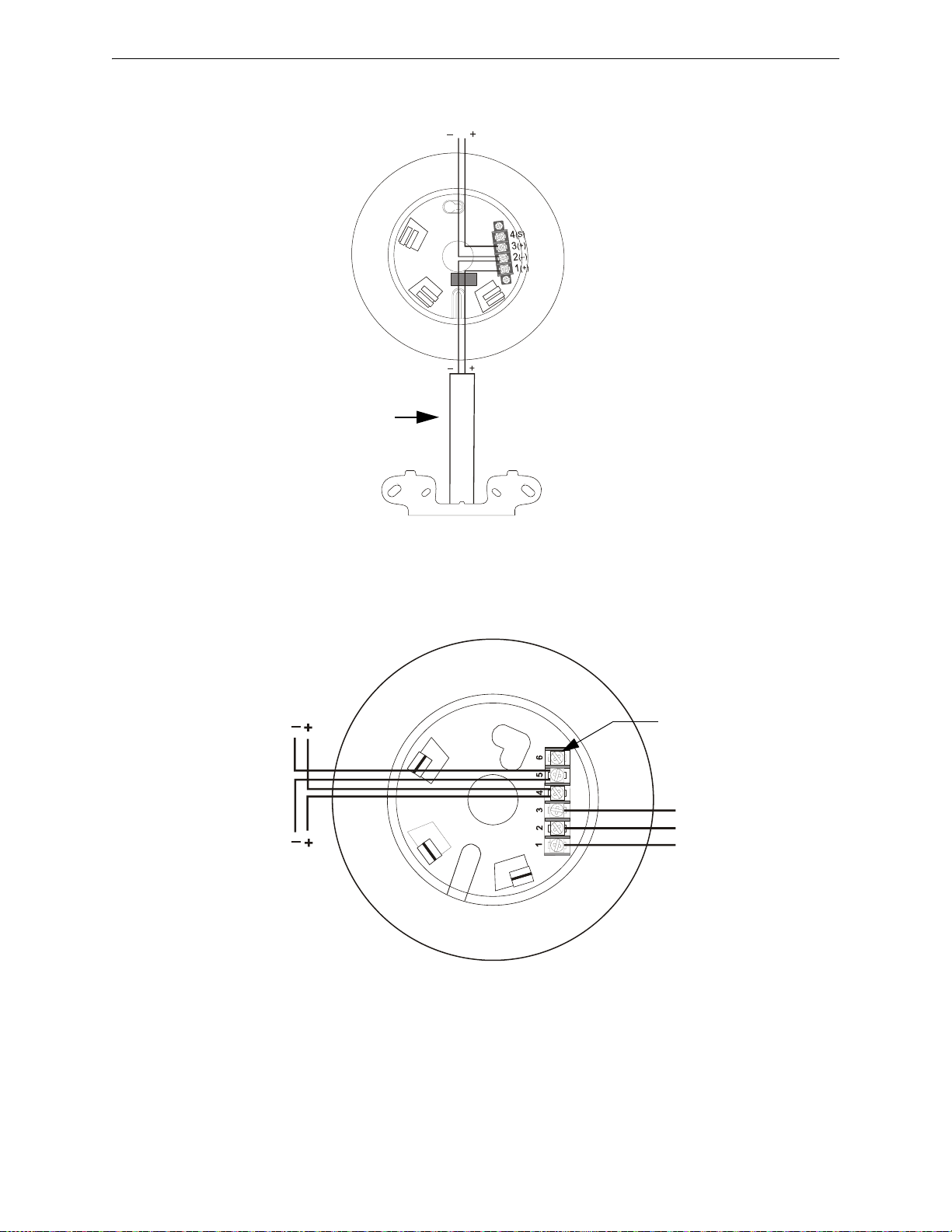
B224BI Isolator Base Intelligent Detector Base Layouts for Legacy Devices
SLC In
SLC Out
S
L
C
-
2
2
4
B
I
w
ir
e
.
w
m
f
Conduit
I300
Isolator Module
Figure D.2 Wiring the Legacy B224BI Isolator Base
SLC
b
2
2
4
r
b
.
w
m
f
To next device
on SLC
For connection of
cable shield
3
R
e
la
y
C
o
m
m
o
n
2
N
o
r
m
a
lly
O
p
e
n
1
N
o
r
m
a
lly
C
lo
s
e
d
Figure D.3 Wiring the Legacy B224RB Relay Base
D.2 B224BI Isolator Base
D.3 B224RB Relay Base
FireLite SLC Wiring Manual — P/N 51309:P4 9/17/2014 79
Page 80

Intelligent Detector Base Layouts for Legacy Devices B501BH(-2) and B501BHT(-2) Sounder Bases
+ -
s
lc
-
b
5
0
1
b
h
w
ir
in
g
.
w
m
f
Figure D.4 Wiring the Legacy B501BH(-2) and B501BHT(-2) Sounder Bases
SLC -SLC +
UL-Listed
24V Power
Supply
Optional
Sounder
Interconnect
D.4 B501BH(-2) and B501BHT(-2) Sounder Bases
80 FireLite SLC Wiring Manual — P/N 51309:P4 9/17/2014
Page 81

Notes
FireLite SLC Wiring Manual — P/N 51309:P4 9/17/2014 81
Page 82

Appendix E: Canadian Versions of SLC Devices
UL-listed SLC Device ULC-listed SLC Device Description
Detectors
AD350/AD355 AD350A/AD355A Intelligent detector that combines a photoelectric sensing chamber and fixed
temperature heat detection (135°F/57.2°C).
CP350/CP355 CP350A/CP-355A Addressable, intelligent smoke detector that incorporates an ionization sensing
chamber. Designed to provide open area protection.
SD350/SD355 SD350A/SD355A Addressable intelligent smoke detector that uses a photoelectric sensing
SD350T/SD355T SD350TA/SD355TA Adds thermal sensor s that will alarm at a fixed temperature of 135°F (57°C).
H350/H355 H350A/H355A Intelligent thermistor sensing circuit for fast response. Designed to provide
H350R/H355R H350RA/H355RA Incorporates a thermal rate of rise of 15°F (9.4°C).
H355HT H355HTA High temperature sensor with 190°F (87.8°C) fixed temperature alarm.
DNR DNRA Photoelectric Duct Detector, Low-flow. Requires SD350(A)/SD355(A) detector.
Bases
B210LP B210LPA Standard U.S. Low-Profile base (6", 15.24 cm).
B501 B501A Standard European flangeless base (4", 10.16 cm).
B501BH, B501BHT B501BHA, B501BHTA Sounder base, includes Sounder base with temporal sounder (UL 8th Edition).
B501BH-2, B501BHT-2 N/A Sounder base, includes Sounder base with temporal sounder (UL 9th Edition).
B224RB B224RBA Low Profile Intelligent relay base.
B224BI B224BIA Low Profile Intelligent isolator base.
B200SR B200SRA Intelligent sounder base, temporal or steady.
B200SR-LF N/A Intelligent sounder base for low frequency applications
Monitor and Zone Interface Modules
MMF-300 MMF-300A Used for normally open contact alarm initiating devices, such as manual pull
MMF-302 MMF-302A Used to interface with two-wire smoke detectors in addition to normally open
MDF-300 MDF-300A Two independent 2-wire Initiating Device Circuits (IDCs) at two separate,
MMF-301 MMF-301A Functionally similar to the MMF-300 Monitor Module, but offered in a smaller
BG-12LX BG-12LX An addressable manual pull station with key-lock reset feature. The
Control Modules
CMF-300 CMF-300A Control Module, NAC: Addressable Control Module used as Notification
CRF-300 CRF-300A Relay Control Module is similar to the CMF-300(A) except used as a Form-C
chamber. Listed for use in ducts. Designed to provide open area protection.
open area protection with 50 foot spacing capability. A fixed temperature
sensor with 135°F fixed temperature alarm.
stations, four-wire smoke detectors, heat detectors, waterflow, and supervisory
devices.
contacts.
consecutive addresses. Wire supervised IDCs as NFPA Style B (Class B) or
Style D (Class A) circuits. The modules come with a thermoplastic cover for
mounting to a 4-inch (10.16 cm) square mounting box.
package for mounting directly in the electrical box of the device being
monitored. (Class B input circuit only.)
addressable module is housed within the pull station.
Appliance Circuits (NACs) to power and supervise compatible, UL-listed
notification appliances. Wired supervised NACs as NFPA Style Y (Class B) or
Style Z (Class A). The modules come with a thermoplastic cover for mounting
to a 4-inch (10.16 cm) square mounting box.
control relay module.
82 FireLite SLC Wiring Manual — P/N 51309:P4 9/17/2014
Page 83

Canadian Versions of SLC Devices
UL-listed SLC Device ULC-listed SLC Device Description
Fault Isolator Module
I300 I300A The Fault Isolator Module protects the system against wire-to-wire short circuits
on the SLC. It should be placed between groups of sensors in a Style 6 or
Style 7 SLC to isolate short- and open-circuit problems and protect the rest of
the loop so it can continue to operate normally. It is not addressable, but listed
here due to its use in an SLC.
ISO-6 ISO-6A The Six Fault Isolator Module protects the system against wire-to-wire short
circuits on six isolated SLC circuits. Functionally the same as six I300 modules.
Multi-input/output modules
MMF-300-10 MMF-300-10A Supervises ten Class-B addressable Initiating Device Circuits (IDC) which
MMF-302-6 MMF-302-6A Monitors six zones of conventional two-wire detectors.
CDRM-300 CDRM-300A Dual Class B monitor / Form-C relay module.
CMF-300-6 CMF-300-6A Similar in operation to the CMF-300, except it can activate six (6) Style Y
CRF-300-6 CRF-300-6A Similar in operation to the CRF-300, except it provides six (6) Form-C relays.
monitor normally open contact initiating devices.
(Class B) or three (3) Style Z (Class A) NACs.
FireLite SLC Wiring Manual — P/N 51309:P4 9/17/2014 83
Page 84

Index
Numerics
24 VDC detectors 68
24 VDC NAC power
24 VDC power
MS-9200, MS-9600
46
18
A
AD350 Detector 11
AD355 Detector
address capacity
addressable
modules
addressable devices
Addressable Modules (Overview)
Addressable Monitor Modules
Alarm Verification
analog intelligent devices
Authority Having Jurisdiction
auxiliary devices
11, 59
23
11, 29
23
82
29
59
10
13
11
B
B200SR Sounder Detector Base 59
B200SR-LF Sounder Detector Base for Low Fre-
59
quency
B210LP
B224BI Isolator Detector Base
B224RB Relay Detector Base
B350LP Detector Base
B501 Detector Base
B501BH Sounder Detector Base
B501BH-2 Sounder Detector Base
B501BHT Temporal Sounder Detector Base
B501BHT-2 Temporal Sounder Detector Base
base
BEAM355
BEAM355S
BG-12LX
building entry/exit
59
23, 59
59
78
59, 78
59
59
59
59
60, 61, 62
12, 65
12, 65
12, 67
71
C
CDRM-300 57
CDRM-300 Multiple Input/Output Module
58
wiring
circuit fault
Classic Loop Interface Protocol
CLIP (Classic Loop Interface Protocol)
CLIP Mode
close nippled conduit
CMF-300 Control Module
11
13
installation
47
wiring
10
10
28
11, 46, 47, 48
46
CMF-300-6 Control Module
address disabling
address setting
circuit board
installation
short circuit protection
Style selection
51
wiring
common ground
communication protocol
conduit, close nippled
connectors, crimp-on
Control Modules
Overview
control panel
CP350 Detector
12
CP355
CP355 Detector
CRF-300 Relay Module
53
wiring
CRF-300-6 Relay Module
address disabling
address setting
circuit board
54, 55
wiring
48
50
48
49
71
11
82
8
12
59
55
54
11, 46, 51, 52
49
49
10
28
72, 73
11, 53
11, 53
55
D
D350P Detector 12
D350RP Detector
D355PL detector
DC resistance
detector bases
detector bases, wiring of
detectors
devices
document sources
drain wire
dry-contact
DTK-2LVLP-F
Dual Monitor Module
59
detector bases
listing
addressable
auxiliary
maximum number between isolators
supervised
12
12
15, 16
59
60
82
12, 82
23
11
69
9
17
11
71
33
E
electrical interference 14
emergency signaling circuit
End-of-Line Resistor
38
47, 51
23
84 FireLite SLC Wiring Manual — P/N 51309:P4 9/17/2014
Page 85

Index F–P
F
fault 13, 27
fault condition
Fault Isolator Module
FCPS-24F
Fire alarm service
17
foil
Form-C contacts
Form-C relay contacts
four-wire configuration
23
23
68
33
57
11, 53, 59
48, 52
G
ground terminal 72, 73
H
H350 Detector 12
H350R Detector
H355 Detector
H355HT Detector
H355R Detector
Heat Detector
12
12, 59
12
12
59
I
I300 Isolator Module 11, 23
Initiating Device Circuits
integral relay
Ionization Detector
ISO-6 Isolator Module
ISO-6 Isolator module
isolator base
isolator base, wiring of
Isolator Module
how it works
wiring of
23
23
11, 27, 28
24
29, 36, 39, 41
59
23
11
61
23
K
key-lock reset 67
L
LEDs 59
LiteSpeed
local building code
loop resistance
loops
10
71
15, 16
16
MMF-300-10 Monitor Module
39
wiring
MMF-301 Mini Monitor Module
MMF-302 Zone Interface Module
42
wiring
MMF-302-6 Interface Module
44
wiring
module circuits
modules
addressable
control
isolator
monitor
relay
Monitor Modules
Overview
Multicriteria Detector
multiple input/output module
Multi-Point Module
29
11
11
11
11
11
11, 29
82
59
35
11, 30, 39, 40
11, 33
11, 31, 42, 43
11, 32, 44, 45
57
N
NAC 11
NAC power
NAC wiring
NEC Article 800
NFPA Style 4
NFPA Style 6
NFPA Style 7
NFPA Style B
NFPA Style D
NFPA Style Y
NFPA Style Z
Nonresettable power
normally closed contacts
Notification Appliance Circuit
46, 69
46
71
wiring of
with I300
wiring of
with I300
21
25, 26
22
27
23
with isolator modules
IDC wiring
IDC wiring
36, 39, 41, 42, 44
37, 40, 43, 45
46
wiring of
47, 51
46
wiring of
48, 52
18
69
28
11
O
older version and newer version modules 8, 9
M
MDF-300 Dual Monitor Module 11, 33, 41
41
wiring
metal conduit
Mini Monitor Module
minimum resistance
MMF-300 Monitor Module
wiring
FireLite SLC Wiring Manual — P/N 51309:P4 9/17/2014 85
17, 27
33
68
11, 29, 36, 37, 38
36
P
performance 13
Photoelectric Detector
PLP-42N
Polling Protocols
power run
power supervision relay
71
10
68, 69
59
47, 48, 51, 52, 69
Page 86

R–Z Index
power supplies 68
proper gauge wire
pull station
wiring of
68
12, 28
67
R
RA100Z 60
RA400Z
rate of rise
ratings, relay contact
relay base
relay contact ratings
Relay Module
relays
Remote LED Annunciator
Resettable power
resistance
rotary switches
60
12
23
wiring of
Form-C
15, 16
46, 53, 57
61
46, 53, 57
11
11
18
34, 40, 41, 42, 43, 44, 45, 59
S
SD350 Detector 12
SD350T Detector
SD355 Detector
SD355R Detector
SD355T Detector
sensing circuit, thermistor
short circuit
Signaling Line Circuit
Single Point Module
SLC address, setting of
SLC connections
SLC terminal block
SLC wiring
45
SLCP-30
Smoke Detectors
sounder base
sounder base, wiring of
Sprinkler supervision
supervised
supplying power
suppressors, surge
surge protector
switching
71
circuit
devices
46
12
12, 59
12
12
23
10
34
34, 59
18
17
36, 37, 38, 39, 40, 41, 42, 43, 44,
59
23
62
33
69
69
68
71
10, 13, 71
60
12
T-tapping
twisted-pair shielded wiring
two-wire configuration
two-wire detectors
15, 21, 22, 27, 28
14
47, 51
69
U
Unregulated power 18
V
verification cycle 59
W
Waterflow alarm service, automatic and manual
33
W-GATE
wire length
wire size
wireless gateway
wiring
wiring pair
wiring requirements
wiring style requirements
12, 62
external power
SLC connections
SLC power
64
63
15, 16
14
12, 62
external power
SLC connections
SLC power
24
I300
24
ISO-6
MDF-300
MMF-300
MMF-300-10
MMF-302
MMF-302-6
46
NACs
64
63
41
36
39
42
44
71
14
62
62
13
Z
Zone Interface Module 31
T
terminal blocks 18
termination of shield
Thermal Detector
thermistor sensing circuit
trouble conditions
86 FireLite SLC Wiring Manual — P/N 51309:P4 9/17/2014
17
59
12
13, 23
Page 87

Manufacturer Warranties and Limitation of Liability
Manufacturer Warranties. Subject to the limitations set forth herein,
Manufacturer warrants that the Products manufactured by it in its
Northford, Connecticut facility and sold by it to its authorized
Distributors shall be free, under normal use and service, from defects
in material and workmanship for a period of thirty six months (36)
months from the date of manufacture (effective Jan. 1, 2009). The
Products manufactured and sold by Manufacturer are date stamped at
the time of production. Manufacturer does not warrant Products that
are not manufactured by it in its Northford, Connecticut facility but
assigns to its Distributor, to the extent possible, any warranty offered
by the manufacturer of such product. This warranty shall be void if a
Product is altered, serviced or repaired by anyone other than
Manufacturer or its authorized Distributors. This warranty shall also
be void if there is a failure to maintain the Products and the systems in
which they operate in proper working conditions.
MANUFACTURER MAKES NO FURTHER WARRANTIES, AND
DISCLAIMS ANY AND ALL OTHER WARRANTIES, EITHER
EXPRESSED OR IMPLIED, WITH RESPECT TO THE PRODUCTS,
TRADEMARKS, PROGRAMS AND SERVICES RENDERED BY
MANUFACTURER INCLUDING WITHOUT LIMITATION,
INFRINGEMENT, TITLE, MERCHANTABILITY, OR FITNESS FOR
ANY PA RTICULAR PURPOSE. MANUFACTURER SHALL NOT BE
LIABLE FOR ANY PERSONAL INJURY OR DEATH WHICH MAY
ARISE IN THE COURSE OF, OR AS A RESULT OF, PERSONAL,
COMMERCIAL OR INDUSTRIAL USES OF ITS PRODUCTS.
This document constitutes the only warranty made by Manufacturer
with respect to its products and replaces all previous warranties a nd is
the only warranty made by Manufacturer. No increase or alteration,
written or verbal, of the obligation of this warranty is authorized.
Manufacturer does not represent that its products will preven t any loss
by fire or otherwise.
Warranty Claims. Manufacturer shall replace or repair, at
Manufacturer's discretion, each part returned by its authorized
Distributor and acknowledged by Manufacturer to be defective,
provided that such part shall have been returned to Manufacturer with
all charges prepaid and the authorized Distributor has completed
Manufacturer's Return Material Authorization form. The replacement
part shall come from Manufacturer's stock and may be new or
refurbished. THE FOREGOING IS DISTRIBUTOR'S SOLE AND
EXCLUSIVE REMEDY IN THE EVENT OF A WARRANTY CLAIM.
Warn-HL-08-2009.fm
FireLite SLC Wiring Manual — P/N 51309:P4 9/17/2014 87
Page 88

World Headquarters
1 Firelite Place
Northford, CT 06472-1653 USA
203-484-7161
fax 203-484-7118
www.firelite.com
 Loading...