

Page 1

™
Captuvo Enterprise Sled
Series
User’s Guide
Page 2

Disclaimer
Honeywell International Inc. (“HII”) reserves the right to make changes in specifications and other information contained in this document without prior notice,
and the reader should in all cases consult HII to determine whether any such
changes have been made. The information in this publication does not represent a commitment on the part of HII.
HII shall not be liable for technical or editorial errors or omissions contained
herein; nor for incidental or consequential damages resulting from the furnishing, performance, or use of this material.
This document contains proprietary information that is protected by copyright.
All rights are reserved. No part of this document may be photocopied, reproduced, or translated into another language without the prior written consent of
HII.
2014 Honeywell International Inc. All rights reserved.
Other product names or marks mentioned in this document may be trademarks
or registered trademarks of other companies and are the property of their
respective owners.
Web Address:
Apple, iPod touch, iPhone5, and iPad mini are trademarks of Apple Inc., registered in the U.S. and other countries. App Store is a service mark of Apple Inc.
Other product names or marks mentioned in this document may be trademarks
or registered trademarks of other companies and are the property of their
respective owners.
www.honeywellaidc.com
Patents
For patent information, please refer to www.hsmpats.com.
Page 3

Table of Contents
Chapter 1 - Getting Started
Introduction ................................................................. 1-1
Out of the Box ............................................................. 1-1
Operating Temperature............................................... 1-1
Reading Techniques ................................................... 1-2
Setting Custom Defaults ............................................. 1-2
Resetting the Custom Defaults ................................... 1-3
Resetting the Factory Defaults.................................... 1-4
Chapter 2 - Input/Output Settings
Good Read and Error Indicators ................................. 2-1
Beeper – Good Read ............................................ 2-1
Beeper Volume – Good Read ............................... 2-1
Manual Trigger Mode .................................................. 2-2
Mobile Phone Read Mode........................................... 2-2
Centering..................................................................... 2-2
Preferred Symbology .................................................. 2-4
High Priority Symbology ........................................ 2-5
Low Priority Symbology......................................... 2-5
Preferred Symbology Time-out ............................. 2-5
Preferred Symbology Default ................................ 2-6
Output Sequence Overview ........................................ 2-6
Require Output Sequence..................................... 2-6
Output Sequence Editor ........................................ 2-6
To Add an Output Sequence................................. 2-7
Other Programming Selections ............................. 2-7
Output Sequence Editor ........................................ 2-9
Partial Sequence ................................................... 2-9
Require Output Sequence................................... 2-10
Multiple Symbols ....................................................... 2-10
No Read .................................................................... 2-11
Video Reverse........................................................... 2-11
Working Orientation .................................................. 2-12
i
Page 4

Chapter 3 - Data Editing
Prefix/Suffix Overview..................................................3-1
To Add a Prefix or Suffix:....................................... 3-1
To Clear One or All Prefixes or Suffixes ................3-2
To Add a Carriage Return Suffix to All Symbologies3-
3
Prefix Selections ..........................................................3-3
Suffix Selections ..........................................................3-4
Function Code Transmit ..............................................3-4
Chapter 4 - Data Formatting
Data Format Editor Introduction...................................4-1
To Add a Data Format .................................................4-1
Other Programming Selections.............................. 4-3
Terminal ID Table ........................................................4-4
Data Format Editor Commands ...................................4-4
Move Commands................................................... 4-8
Search Commands ................................................4-9
Miscellaneous Commands................................... 4-12
Data Formatter...........................................................4-15
Data Format Non-Match Error Tone ....................4-16
Primary/Alternate Data Formats ................................4-17
Single Scan Data Format Change .......................4-17
Chapter 5 - Symbologies
All Symbologies ...........................................................5-2
Message Length Description .......................................5-2
Codabar .......................................................................5-3
Codabar Concatenation......................................... 5-4
Code 39 .......................................................................5-6
Code 32 Pharmaceutical (PARAF) ........................5-8
Full ASCII............................................................... 5-9
Code 39 Code Page .............................................. 5-9
Interleaved 2 of 5.......................................................5-10
NEC 2 of 5 .................................................................5-12
ii
Page 5

Code 93..................................................................... 5-14
Code 93 Code Page............................................ 5-14
Straight 2 of 5 Industrial (three-bar start/stop) .......... 5-15
Straight 2 of 5 IATA (two-bar start/stop).................... 5-16
Matrix 2 of 5 .............................................................. 5-17
Code 11..................................................................... 5-18
Code 128................................................................... 5-19
ISBT 128 Concatenation ..................................... 5-19
Code 128 Code Page.......................................... 5-21
GS1-128.................................................................... 5-22
Telepen ..................................................................... 5-23
UPC-A ....................................................................... 5-24
UPC-A/EAN-13
with Extended Coupon Code .................................. 5-26
UPC-E0 ..................................................................... 5-27
UPC-E1 ..................................................................... 5-30
EAN/JAN-13.............................................................. 5-31
Convert UPC-A to EAN-13 .................................. 5-31
ISBN Translate .................................................... 5-33
EAN/JAN-8................................................................ 5-34
MSI............................................................................ 5-36
GS1 DataBar Omnidirectional................................... 5-38
GS1 DataBar Limited ................................................ 5-38
GS1 DataBar Expanded............................................ 5-39
Trioptic Code............................................................. 5-40
Codablock A.............................................................. 5-40
Codablock F .............................................................. 5-42
PDF417 ..................................................................... 5-43
MicroPDF417 ............................................................ 5-44
GS1 Composite Codes ............................................. 5-45
UPC/EAN Version ............................................... 5-45
GS1 Emulation .......................................................... 5-46
TCIF Linked Code 39 (TLC39).................................. 5-47
QR Code ................................................................... 5-47
Data Matrix................................................................ 5-49
Data Matrix Code Page ....................................... 5-50
MaxiCode .................................................................. 5-51
iii
Page 6

Aztec Code ................................................................5-52
Aztec Code Page................................................. 5-53
Chinese Sensible (Han Xin) Code .............................5-54
Postal Codes - 2D......................................................5-55
Single 2D Postal Codes:...................................... 5-55
Combination 2D Postal Codes:............................ 5-56
Postal Codes - Linear ................................................5-58
China Post (Hong Kong 2 of 5)............................ 5-58
Korea Post ...........................................................5-60
Chapter 6 - Serial Programming Commands
Conventions.................................................................6-1
Menu Command Syntax ..............................................6-1
Query Commands........................................................6-2
Responses.............................................................6-2
Resetting the Custom Defaults ....................................6-4
Menu Commands ........................................................6-5
Chapter 7 - Maintenance
Repairs ........................................................................7-1
Healthcare Housing Cleaning Directions (Healthcare unit
only)...........................................................................7-1
Inspecting Cords and Connectors ...............................7-1
Troubleshooting...........................................................7-1
Chapter 8 - Customer Support
Technical Assistance ...................................................8-1
Appendix A - Reference Charts
Symbology Charts ...................................................... A-1
Linear Symbologies ...............................................A-1
2D Symbologies.....................................................A-3
Postal Symbologies ...............................................A-3
ASCII Conversion Chart (Code Page 1252)............... A-4
Lower ASCII Reference Table .................................... A-5
iv
Page 7

ISO 2022/ISO 646 Character Replacements ............A-10
v
Page 8

vi
Page 9

1
Getting Started
Introduction
The Captuvo Enterprise Sleds include an optional integrated imager for scanning all types of bar codes. You have the capability to configure the scan engine
in the sled using the programming bar codes included in this user’s guide; however, the application being used might override the settings you have programmed. An optional magnetic stripe reader (MSR) for reading cards with
magnetic stripes is also available.
Out of the Box
Verify that the box contains the following items:
• Captuvo Enterprise Sled
• Charger (if appropriate)
• USB Cable
• Quick Start Guide
• Regulatory Sheet
Note: If you ordered accessories for your sled, verify that they are also included
with the order.
Be sure to keep the original packaging in case you need to return the sled for
service.
Note: Honeywell is not an authorized Apple repair center. Please return only
your sled to us for repair. Honeywell is not liable for any non-Honeywell
product shipped to our repair center.
Note: Refer to your Apple device’s documentation for important product and
safety information.
Operating Temperature
The maximum operating temperature range for the Captuvo sled is 0°C to 35°C
(32°F to 95°F).
1 - 1
Page 10
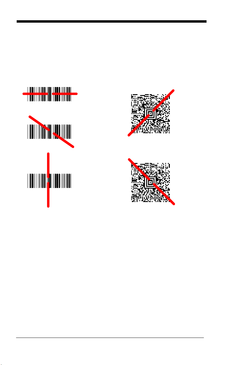
Reading Techniques
Linear bar code 2D Matrix symbol
The sled has a view finder that projects a bright red aiming beam that corresponds to the sled’s horizontal field of view. The aiming beam should be centered over the bar code, but it can be positioned in any direction for a good read.
The aiming beam is smaller when the sled is closer to the code and larger when
it is farther from the code. Symbologies with smaller bars or elements (mil size)
should be read closer to the unit. Symbologies with larger bars or elements (mil
size) should be read farther from the unit. To read single or multiple symbols
(on a page or on an object), hold the sled at an appropriate distance from the
target, pull the trigger, and center the aiming beam on the symbol. If the code
being scanned is highly reflective (e.g., laminated), it may be necessary to tilt
the code up 15° to 18° to prevent unwanted reflection.
Setting Custom Defaults
You have the ability to create a set of menu commands as your own, custom
defaults. To do so, scan the Set Custom Defaults bar code below before scanning the menu commands for your custom defaults. If a menu command
requires scanning numeric codes from the back cover, then a Save code, that
1 - 2
Page 11

entire sequence will be saved to your custom defaults. When you have entered
Save Custom Defaults
Set Custom Defaults
Activate Custom Defaults
all the commands you want to save for your custom defaults, scan the Save
Custom Defaults bar code.
You may have a series of custom settings and want to correct a single setting.
To do so, just scan the new setting to overwrite the old one. For example, if you
had previously saved the setting for Beeper Volume at Low to your custom
defaults, and decide you want the beeper volume set to High, just scan the Set
Custom Defaults bar code, then scan the Beeper Volume High menu code,
and then Save Custom Defaults. The rest of the custom defaults will remain,
but the beeper volume setting will be updated.
Resetting the Custom Defaults
If you want the custom default settings restored to your sled, scan the Activate
Custom Defaults bar code below. This is the recommended default bar code
for most users. It resets the sled to the custom default settings. If there are no
custom defaults, it will reset the sled to the factory default settings. Any settings
that have not been specified through the custom defaults will be defaulted to the
factory default settings.
1 - 3
Page 12

Resetting the Factory Defaults
!
Remove Custom Defaults
Activate Defaults
This selection erases all your settings and resets the sled to the original
factory defaults. It also disables all plugins.
If you aren’t sure what programming options are in your sled, or you’ve changed
some options and want to restore the sled to factory default settings, first scan
the Remove Custom Defaults bar code, then scan Activate Defaults. This
resets the sled to the factory default settings.
The Menu Commands, beginning on page 6-5 list the factory default settings for
each of the commands (indicated by an asterisk (*) on the programming pages).
1 - 4
Page 13
2
* Beeper - Good Read On
Beeper - Good Read Off
* High
Medium
Off
Low
Input/Output Settings
Good Read and Error Indicators
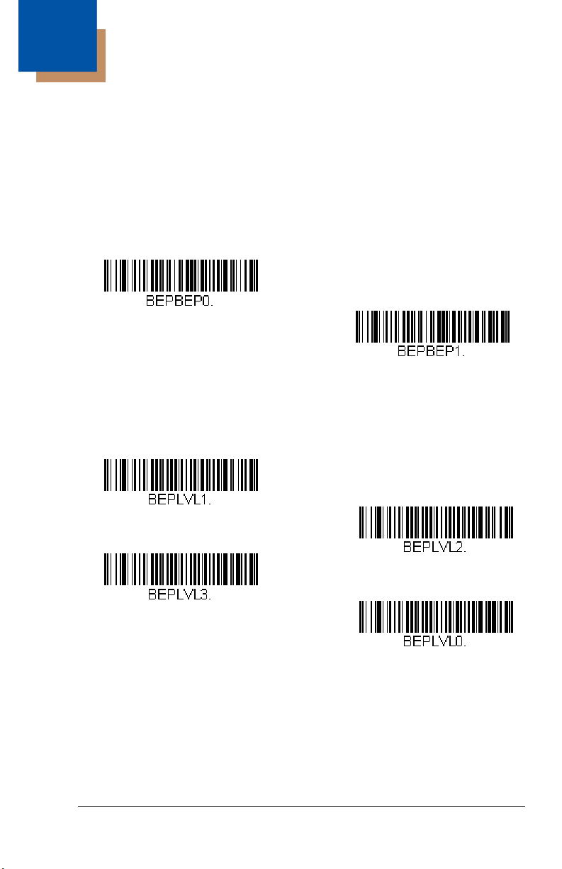
Beeper – Good Read
The beeper may be programmed On or Off in response to a good read.
Turning this option off, only turns off the beeper response to a good read
indication. All error and menu beeps are still audible. Default = Beeper -
Good Read On.
Beeper Volume – Good Read
The beeper volume codes modify the volume of the beep the sled emits on
a good read. Default = High.
2 - 1
Page 14

Manual Trigger Mode
Manual Trigger - Normal
Hand Held Scanning - Mobile
Phone
When in manual trigger mode, the scanner scans until a bar code is read, or
until the trigger is released. Normal mode offers good scan speed and the longest working ranges (depth of field). Default = Manual Trigger-Normal.
Mobile Phone Read Mode
When this mode is selected, your sled is optimized to read bar codes from
mobile phone or other LED displays. However, the speed of scanning printed
bar codes may be slightly lower when this mode is enabled.
Note: To turn off Mobile Phone Read Mode, scan a Manual Trigger Mode bar
code (see page 2-2).
Centering
Use Centering to narrow the sled’s field of view to make sure the sled reads
only those bar codes intended by the user. For instance, if multiple codes are
placed closely together, centering will insure that only the desired codes are
read.
If a bar code is not touched by a predefined window, it will not be decoded or
output by the scanner. If centering is turned on by scanning Centering On, the
scanner only reads codes that pass through the centering window you specify
using the Top of Centering Window, Bottom of Centering Window, Left, and
Right of Centering Window bar codes.
2 - 2
Page 15
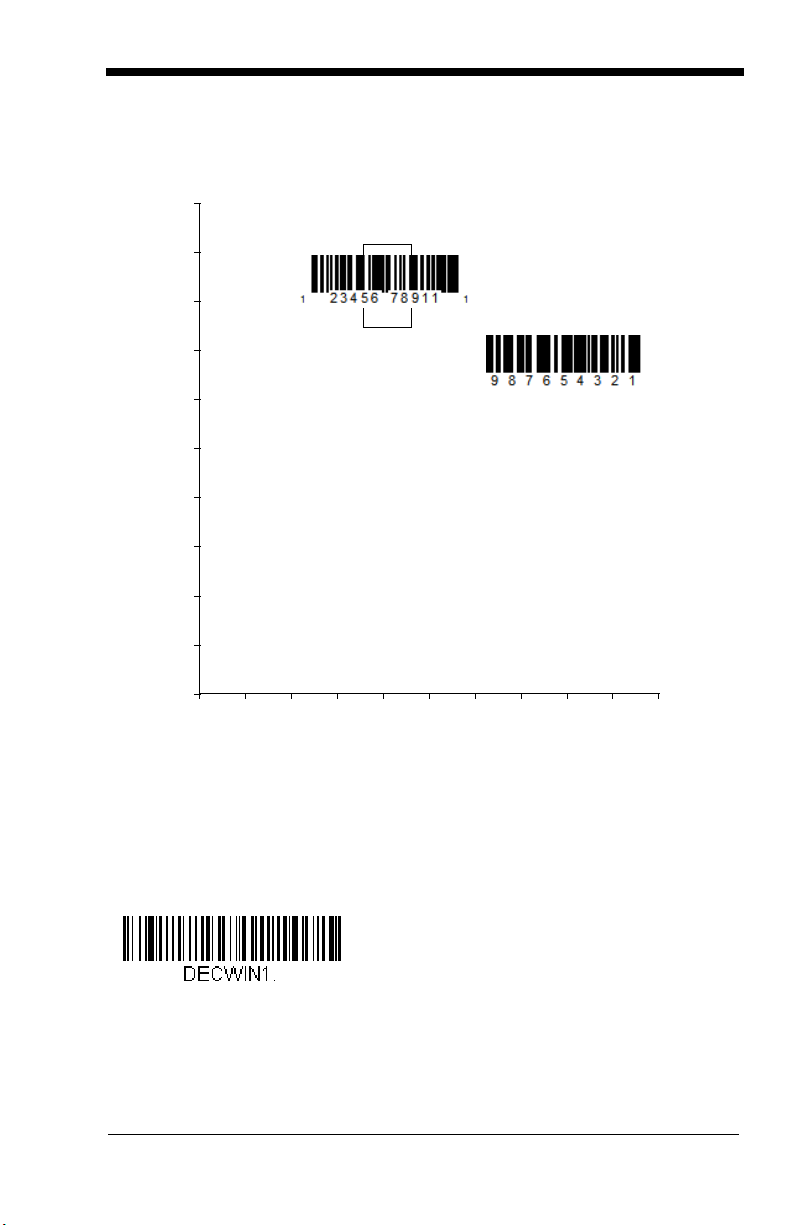
In the example below, the white box is the centering window. The centering win-
0
Bar Code 1
Bar Code 2
10 20 30 40 50 60 70 80 90 100%
100
90
80
70
60
50
40
30
20
10
0%
Centering On
dow has been set to 20% left, 30% right, 8% top, and 25% bottom. Since Bar
Code 1 passes through the centering window, it will be read. Bar Code 2 does
not pass through the centering window, so it will not be read.
Note: A bar code needs only to be touched by the centering window in order to
be read. It does not need to pass completely through the centering
window.
Scan Centering On, then scan one of the following bar codes to change the
top, bottom, left, or right of the centering window. Then scan the percent you
want to shift the centering window using digits on the inside back cover of this
manual. Scan Save. Default Centering = 40% for Top and Left, 60% for Bot-
tom and Right.
2 - 3
Page 16
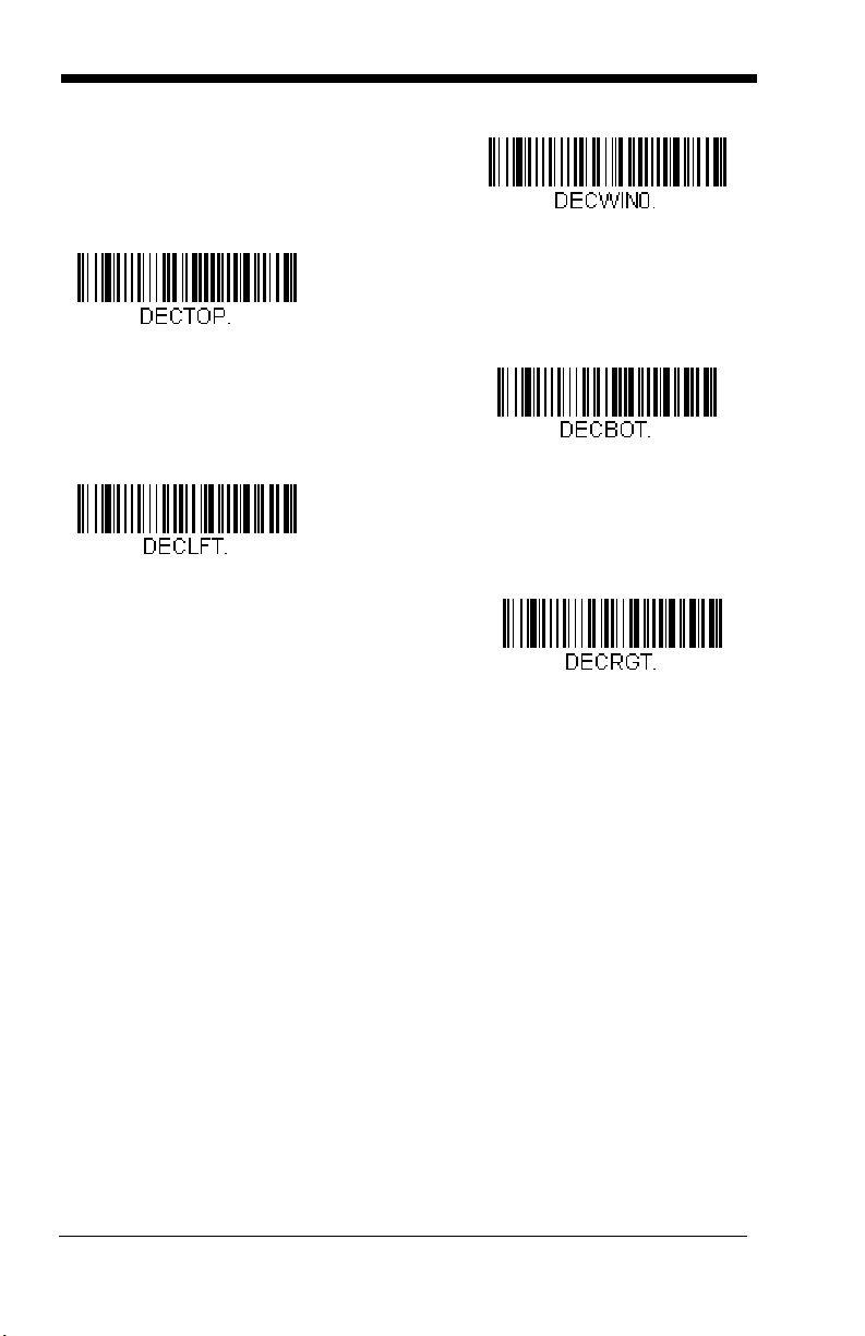
Preferred Symbology
* Centering Off
Top of Centering Window
Bottom of Centering Window
Left of Centering Window
Right of Centering Window
The sled can be programmed to specify one symbology as a higher priority over
other symbologies in situations where both bar code symbologies appear on
the same label, but the lower priority symbology cannot be disabled.
For example, you may be using the sled in a retail setting to read U.P.C. symbols, but have occasional need to read a code on a drivers license. Since some
licenses have a Code 39 symbol as well as the PDF417 symbol, you can use
Preferred Symbology to specify that the PDF417 symbol be read instead of the
Code 39.
Preferred Symbology classifies each symbology as high priority, low priority,
or as an unspecified type. When a low priority symbology is presented, the
sled ignores it for a set period of time (see Preferred Symbology Time-out on
page 2-5) while it searches for the high priority symbology. If a high priority
symbology is located during this period, then that data is read immediately.
If the time-out period expires before a high priority symbology is read, the sled
will read any bar code in its view (low priority or unspecified). If there is no bar
code in the sled’s view after the time-out period expires, then no data is
reported.
Note: A low priority symbol must be centered on the aiming pattern to be read.
2 - 4
Page 17
Scan a bar code below to enable or disable Preferred Symbology. Default =
* Preferred Symbology Off
Preferred Symbology On
High Priority Symbology
Low Priority Symbology
Preferred Symbology Off.
High Priority Symbology
To specify the high priority symbology, scan the High Priority Symbology
bar code below. On the Symbology Charts on page A-1, find the symbology you want to set as high priority. Locate the Hex value for that symbology and scan the 2 digit hex value from the Programming Chart (inside
back cover). Scan Save to save your selection. Default = None
Low Priority Symbology
To specify the low priority symbology, scan the Low Priority Symbology bar
code below. On the Symbology Charts on page A-1, find the symbology
you want to set as low priority. Locate the Hex value for that symbology
and scan the 2 digit hex value from the Programming Chart (inside back
cover).
If you want to set additional low priority symbologies, scan FF, then scan
the 2 digit hex value from the Programming Chart for the next symbology.
You can program up to 5 low priority symbologies. Scan Save to save your
selection. Default = None
Preferred Symbology Time-out
Once you have enabled Preferred Symbology and entered the high and low
priority symbologies, you must set the time-out period. This is the period of
time the sled will search for a high priority bar code after a low priority bar
2 - 5
Page 18

code has been encountered. Scan the bar code below, then set the delay
Preferred Symbology Time-out
Preferred Symbology Default
(from 1-3,000 milliseconds) by scanning digits from the inside back cover,
then scanning Save. Default = 500 ms.
Preferred Symbology Default
Scan the bar code below to set all Preferred Symbology entries to their
default values.
Output Sequence Overview
Require Output Sequence
When turned off, the bar code data will be output to the host as the sled
decodes it. When turned on, all output data must conform to an edited
sequence or the sled will not transmit the output data to the host device.
Note: This selection is unavailable when the Multiple Symbols Selection is
turned on.
Output Sequence Editor
This programming selection allows you to program the sled to output data
(when scanning more than one symbol) in whatever order your application
requires, regardless of the order in which the bar codes are scanned.
Reading the Default Sequence symbol programs the sled to the Universal
values, shown below. These are the defaults. Be certain you want to
delete or clear all formats before you read the Default Sequence symbol.
Note: You must hold the trigger while reading each bar code in a sequence.
Note: To make Output Sequence Editor selections, you’ll need to know the
code I.D., code length, and character match(es) your application
requires. Use the Alphanumeric symbols (inside back cover) to read
these options.
2 - 6
Page 19

To Add an Output Sequence
1. Scan the Enter Sequence symbol (see Require Output
Sequence, page 2-10).
2. Code I.D.
On the Symbology Charts on page A-1, find the symbology to which you
want to apply the output sequence format. Locate the Hex value for that
symbology and scan the 2 digit hex value from the Programming Chart
(inside back cover).
3. Length
Specify what length (up to 9999 characters) of data output will be
acceptable for this symbology. Scan the four digit data length from the
Programming Chart. (Note: 50 characters is entered as 0050. 9999 is
a universal number, indicating all lengths.) When calculating the length,
you must count any programmed prefixes, suffixes, or formatted
characters as part of the length (unless using 9999).
4. Character Match Sequences
On the ISO 2022/ISO 646 Character Replacements, page A-10, find the
Hex value that represents the character(s) you want to match. Use the
Programming Chart to read the alphanumeric combination that
represents the ASCII characters. (99 is the Universal number,
indicating all characters.)
5. End Output Sequence Editor
Scan F F to enter an Output Sequence for an additional symbology, or
Save to save your entries.
Other Programming Selections
• Discard
This exits without saving any Output Sequence changes.
2 - 7
Page 20

Output Sequence Example
A - Code 39
B - Code 128
C - Code 93
In this example, you are scanning Code 93, Code 128, and Code 39 bar
codes, but you want the sled to output Code 39 1st, Code 128 2nd, and
Code 93 3rd, as shown below.
Note: Code 93 must be enabled to use this example.
You would set up the sequence editor with the following command line:
SEQBLK62999941FF6A999942FF69999943FF
The breakdown of the command line is shown below:
SEQBLKsequence editor start command
62 code identifier for Code 39
9999 code length that must match for Code 39, 9999 = all lengths
41 start character match for Code 39, 41h = “A”
FF termination string for first code
6A code identifier for Code 128
9999 code length that must match for Code 128, 9999 = all lengths
42 start character match for Code 128, 42h = “B”
FF termination string for second code
69 code identifier for Code 93
9999 code length that must match for Code 93, 9999 = all lengths
43 start character match for Code 93, 43h = “C”
FF termination string for third code
To program the previous example using specific lengths, you would have to
count any programmed prefixes, suffixes, or formatted characters as part of
the length. If you use the example on page 2-8, but assume a <CR> suffix
and specific code lengths, you would use the following command line:
SEQBLK62001241FF6A001342FF69001243FF
The breakdown of the command line is shown below:
2 - 8
Page 21

SEQBLKsequence editor start command
Default Sequence
Enter Sequence
Transmit Partial Sequence
* Discard Partial Sequence
62 code identifier for Code 39
0012 A - Code 39 sample length (11) plus CR suffix (1) = 12
41 start character match for Code 39, 41h = “A”
FF termination string for first code
6A code identifier for Code 128
0013 B - Code 128 sample length (12) plus CR suffix (1) = 13
42 start character match for Code 128, 42h = “B”
FF termination string for second code
69 code identifier for Code 93
0012 C - Code 93 sample length (11) plus CR suffix (1) = 12
43 start character match for Code 93, 43h = “C”
FF termination string for third code
Output Sequence Editor
Partial Sequence
If an output sequence operation is terminated before all your output
sequence criteria are met, the bar code data acquired to that point is a
“partial sequence.”
Scan Discard Partial Sequence to discard partial sequences when the
output sequence operation is terminated before completion. Scan Trans-
mit Partial Sequence to transmit partial sequences. (Any fields in the
sequence where no data match occurred will be skipped in the output.)
2 - 9
Page 22
Require Output Sequence
Required
On/Not Required
*Off
On
* Off
When an output sequence is Required, all output data must conform to an
edited sequence or the sled will not transmit the output data to the host
device. When it’s On/Not Required, the sled will attempt to get the output
data to conform to an edited sequence but, if it cannot, the sled transmits
all output data to the host device as is.
When the output sequence is Off, the bar code data is output to the host as
the sled decodes it. Default = Off.
Note: This selection is unavailable when the Multiple Symbols Selection is
turned on.
Multiple Symbols
When this programming selection is turned On, it allows you to read multiple
symbols with a single pull of the trigger. If you press and hold the trigger, aiming at a series of symbols, it reads unique symbols once, beeping (if turned on)
for each read. The sled attempts to find and decode new symbols as long as
the trigger is pulled. When this programming selection is turned Off, the sled
will only read the symbol closest to the aiming beam. Default = Off.
2 - 10
Page 23

No Read
On
* Off
Video Reverse Only
* Video Reverse Off
VIDREV0.
Video Reverse and Standard Bar
Codes
With No Read turned On, the sled notifies you if a code cannot be read. If using
an EZConfig Tool Scan Data Window (see page 9-3), an “NR” appears when a
code cannot be read. If No Read is turned Off, the “NR” will not appear.
Default = Off.
If you want a different notation than “NR,” for example, “Error,” or “Bad Code,”
you can edit the output message (see Data Formatting beginning on page 4-1).
The hex code for the No Read symbol is 9C.
Video Reverse
Video Reverse is used to allow the sled to read bar codes that are inverted. The
Video Reverse Off bar code below is an example of this type of bar code.
Scan Video Reverse Only to read only inverted bar codes. Scan Video
Reverse and Standard Bar Codes to read both types of codes.
Note: After scanning Video Reverse Only, menu bar codes cannot be read.
You must scan Video Reverse Off or Video Reverse and Standard Bar
Codes in order to read menu bar codes.
Note: Images downloaded from the unit are not reversed. This is a setting for
decoding only.
2 - 11
Page 24
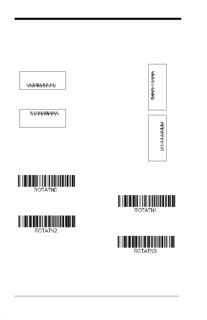
Working Orientation
Upright:
Vertical, Top to Bottom:
(Rotate CW 90°)
Upside Down:
Vertical, Bottom to Top:
(Rotate CCW 90°)
* Upright
Upside Down
Vertical, Top to Bottom
Vertical, Bottom to Top
Some bar codes are direction-sensitive. For example, KIX codes and OCR can
misread when scanned sideways or upside down. Use the working orientation
settings if your direction-sensitive codes will not usually be presented upright to
the scanner. Default = Upright.
Default = Upright.
2 - 12
Page 25

3
Data Editing
Prefix/Suffix Overview
When a bar code is scanned, additional information is sent to the host computer
along with the bar code data. This group of bar code data and additional,
user-defined data is called a “message string.” The selections in this section
are used to build the user-defined data into the message string.
Prefix and Suffix characters are data characters that can be sent before and
after scanned data. You can specify if they should be sent with all symbologies,
or only with specific symbologies. The following illustration shows the breakdown of a message string:
Prefix
alpha numeric &
control characters
Scanned Data
variable length1-11
Suffix
1-11
alpha numeric &
control characters
Points to Keep In Mind
• It is not necessary to build a message string. The selections in this
chapter are only used if you wish to alter the default settings. Default
prefix = None. Default suffix = None.
• A prefix or suffix may be added or cleared from one symbology or all
symbologies.
• You can add any prefix or suffix from the ASCII Conversion Chart (Code
Page 1252), beginning on page A-4, plus Code I.D. and AIM I.D.
• You can string together several entries for several symbologies at one
time.
• Enter prefixes and suffixes in the order in which you want them to appear
on the output.
• When setting up for specific symbologies (as opposed to all
symbologies), the specific symbology ID value counts as an added prefix
or suffix character.
• The maximum size of a prefix or suffix configuration is 200 characters,
which includes header information.
To Add a Prefix or Suffix:
Step 1. Scan the Add Prefix or Add Suffix symbol (page 3-3).
Step 2. Determine the 2 digit Hex value from the Symbology Chart
(included in the Symbology Charts, beginning on page A-1) for the
3 - 1
Page 26

symbology to which you want to apply the prefix or suffix. For
example, for Code 128, Code ID is “j” and Hex ID is “6A”.
Step 3. Scan the 2 hex digits from the Programming Chart inside the back
cover of this manual or scan 9, 9 for all symbologies.
Step 4. Determine the hex value from the ASCII Conversion Chart (Code
Page 1252), beginning on page A-4, for the prefix or suffix you wish
to enter.
Step 5. Scan the 2 digit hex value from the Programming Chart inside the
back cover of this manual.
Step 6. Repeat Steps 4 and 5 for every prefix or suffix character.
Step 7. To add the Code I.D., scan 5, C, 8, 0.
To add AIM I.D., scan 5, C, 8, 1.
To add a backslash (\), scan 5, C, 5, C.
Note: To add a backslash (\) as in Step 7, you must scan 5C twice – once
to create the leading backslash and then to create the backslash
itself.
Step 8. Scan Save to exit and save, or scan Discard to exit without saving.
Repeat Steps 1-6 to add a prefix or suffix for another symbology.
Example: Add a Suffix to a specific symbology
To send a CR (carriage return)Suffix for U.P.C. only:
Step 1. Scan Add Suffix.
Step 2. Determine the 2 digit hex value from the Symbology Chart
(included in the Symbology Charts, beginning on page A-1) for
U.P.C.
Step 3. Scan 6, 3 from the Programming Chart inside the back cover of this
manual.
Step 4. Determine the hex value from the ASCII Conversion Chart (Code
Page 1252), beginning on page A-4, for the CR (carriage return).
Step 5. Scan 0, D from the Programming Chart inside the back cover of this
manual.
Step 6. Scan Save, or scan Discard to exit without saving.
To Clear One or All Prefixes or Suffixes
You can clear a single prefix or suffix, or clear all prefixes/suffixes for a
symbology. If you have been entering prefixes and suffixes for single symbologies, you can use Clear One Prefix (Suffix) to delete a specific character from a symbology. When you Clear All Prefixes (Suffixes), all the
prefixes or suffixes for a symbology are deleted.
3 - 2
Page 27
Step 1. Scan the Clear One Prefix or Clear One Suffix symbol.
Add CR Suffix
All Symbologies
Add Prefix
Clear One Prefix
Clear All Prefixes
Step 2. Determine the 2 digit Hex value from the Symbology Chart
(included in the Symbology Charts, beginning on page A-1) for the
symbology from which you want to clear the prefix or suffix.
Step 3. Scan the 2 digit hex value from the Programming Chart inside the
back cover of this manual or scan 9, 9 for all symbologies.
Your change is automatically saved.
To Add a Carriage Return Suffix to All Symbologies
Scan the following bar code if you wish to add a carriage return suffix to all
symbologies at once. This action first clears all current suffixes, then programs a carriage return suffix for all symbologies.
Prefix Selections
3 - 3
Page 28
Suffix Selections
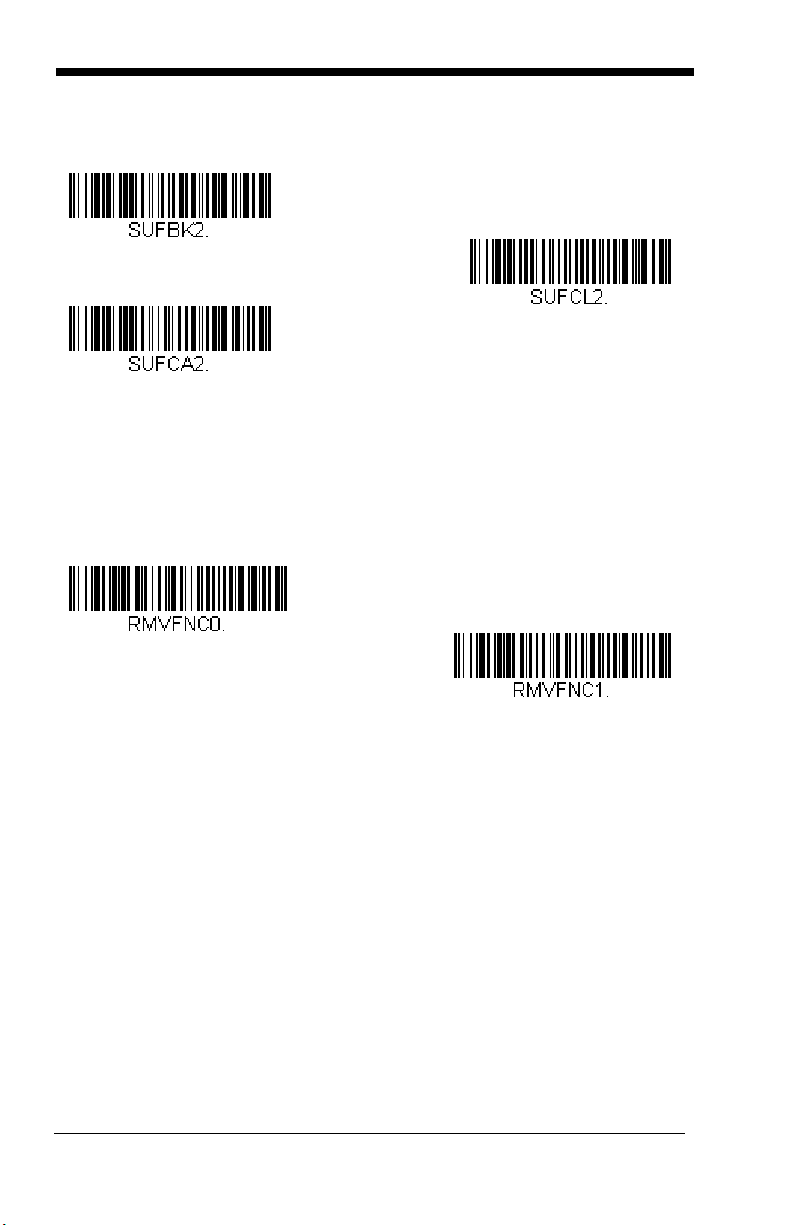
Add Suffix
Clear One Suffix
Clear All Suffixes
* Enable
Disable
Function Code Transmit
When this selection is enabled and function codes are contained within the
scanned data, the sled transmits the function code to the terminal. Charts of
these function codes are provided in Supported Interface Keys starting on
page 8-2. Default = Enable.
3 - 4
Page 29

4
* Default Data Format
Data Formatting
Data Format Editor Introduction
You may use the Data Format Editor to change the sled’s output. For example,
you can use the Data Format Editor to insert characters at certain points in bar
code data as it is scanned. The selections in the following pages are used only
if you wish to alter the output. Default Data Format setting = None.
Normally, when you scan a bar code, it is outputted automatically. However
when you create a format, you must use a “send” command (see Send
Commands on page 4-4) within the format program to output data.
Multiple formats may be programmed into the sled. They are stacked in the
order in which they are entered. However, the following list presents the order
in which formats are applied:
1. Specific Terminal ID, Actual Code ID, Actual Length
2. Specific Terminal ID, Actual Code ID, Universal Length
3. Specific Terminal ID, Universal Code ID, Actual Length
4. Specific Terminal ID, Universal Code ID, Universal Length
5. Universal Terminal ID, Actual Code ID, Actual Length
6. Universal Terminal ID, Actual Code ID, Universal Length
7. Universal Terminal ID, Universal Code ID, Actual Length
8. Universal Terminal ID, Universal Code ID, Universal Length
The maximum size of a data format configuration is 2000 bytes, which includes
header information.
If you have changed data format settings, and wish to clear all formats and
return to the factory defaults, scan the Default Data Format code below.
To Add a Data Format
Step 1. Scan the Enter Data Format symbol (page 4-2).
Step 2. Select Primary/Alternate Format
Determine if this will be your primary data format, or one of 3 alternate
formats. This allows you to save a total of 4 different data formats. To
program your primary format, scan 0 using the Programming Chart
inside the back cover of this manual. If you are programming an
alternate format, scan 1, 2, or 3, depending on which alternate format
4 - 1
Page 30

you are programming. (See Primary/Alternate Data Formats on page
Enter Data Format
Save
4-17 for further information.)
Step 3. Terminal Type
Refer to Terminal ID Table (page 4-4) and locate the Terminal ID
number for your PC. Scan three numeric bar codes on the inside back
cover to program the scanner for your terminal ID (you must enter 3
digits). For example, scan 0 0 3 for an AT wedge.
Note: 099 indicates all terminal types.
Step 4. Code I.D.
In the Symbology Charts, beginning on page A-1, find the symbology to
which you want to apply the data format. Locate the Hex value for that
symbology and scan the 2 digit hex value from the Programming Chart
inside the back cover of this manual.
If you wish to create a data format for all symbologies, with the exception of some specific symbologies, refer to B8 (page 4-14).
If you are creating a data format for Batch Mode Quantity, use 35 for
the Code I.D.
Note: 99 indicates all symbologies.
Step 5. Length
Specify what length (up to 9999 characters) of data will be acceptable
for this symbology. Scan the four digit data length from the
Programming Chart inside the back cover of this manual. For example,
50 characters is entered as 0050.
Note: 9999 indicates all lengths.
Step 6. Editor Commands
Refer to Data Format Editor Commands (page 4-4). Scan the symbols
that represent the command you want to enter. 94 alphanumeric
characters may be entered for each symbology data format.
Step 7. Scan Save to save your data format, or Discard to exit without saving
your changes.
4 - 2
Page 31

Other Programming Selections
Discard
Clear One Data Format
Clear All Data Formats
Save
Discard
Clear One Data Format
This deletes one data format for one symbology. If you are clearing the
primary format, scan 0 from the Programming Chart inside the back
cover of this manual. If you are clearing an alternate format, scan 1, 2,
or 3, depending on the format you are clearing. Scan the Terminal Type
and Code I.D. (see Symbology Charts on page A-1), and the bar code
data length for the specific data format that you want to delete. All other
formats remain unaffected.
Clear all Data Formats
This clears all data formats.
Save to exit and save your data format changes.
Discard to exit without saving any data format changes.
4 - 3
Page 32

Terminal ID Table
Termin al Model(s) Terminal ID
Serial RS232
000
Data Format Editor Commands
When working with the Data Format Editor, a virtual cursor is moved along your
input data string. The following commands are used to both move this cursor to
different positions, and to select, replace, and insert data into the final output.
For examples that use the Data Format Editor commands, refer to Data
Formatter on page 4-15.
Send Commands
Send all characters
Send all characters
F1 Include in the output message all of the characters from the input
message, starting from current cursor position, followed by an insert
character. Syntax = F1xx where xx stands for the insert character’s hex
value for its ASCII code. Refer to the ASCII Conversion Chart (Code
Page 1252), beginning on page A-4 for decimal, hex and character
codes.
Send a number of characters
F2 Include in the output message a number of characters followed by an
insert character. Start from the current cursor position and continue for
“nn” characters or through the last character in the input message,
followed by character “xx.” Syntax = F2nnxx where nn stands for the
numeric value (00-99) for the number of characters, and xx stands for
the insert character’s hex value for its ASCII code. Refer to the ASCII
Conversion Chart (Code Page 1252), beginning on page A-4 for
decimal, hex and character codes.
F2 Example: Send a number of characters
4 - 4
Send the first 10 characters from the bar code above, followed by a
carriage return. Command string: F2100D
F2 is the “Send a number of characters” command
10 is the number of characters to send
0D is the hex value for a CR
The data is output as: 1234567890
F2 and F1 Example: Split characters into 2 lines
Page 33

Send the first 10 characters from the bar code above, followed by a
carriage return, followed by the rest of the characters.
Command string: F2100DF10D
F2 is the “Send a number of characters” command
10 is the number of characters to send for the first line
0D is the hex value for a CR
F1 is the “Send all characters” command
0D is the hex value for a CR
The data is output as: 1234567890
ABCDEFGHIJ
<CR>
Send all characters up to a particular character
F3 Include in the output message all characters from the input message,
starting with the character at the current cursor position and continuing
to, but not including, the search character “ss,” followed by an insert
character. The cursor is moved forward to the “ss” character. Syntax
= F3ssxx where ss stands for the search character’s hex value for its
ASCII code, and xx stands for the insert character’s hex value for its
ASCII code.
Refer to the ASCII Conversion Chart (Code Page 1252), page A-4 for
decimal, hex and character codes.
F3 Example: Send all characters up to a particular character
Using the bar code above, send all characters up to but not including
“D,” followed by a carriage return.
Command string: F3440D
F3 is the “Send all characters up to a particular character” command
44 is the hex value for a 'D”
0D is the hex value for a CR
The data is output as: 1234567890ABC
<CR>
Send all characters up to a string
B9 Include in the output message all characters from the input message,
starting with the character at the current cursor position and continuing
to, but not including, the search string “s...s.” The cursor is moved
forward to the beginning of the “s...s” string. Syntax = B9nnnns...s
where nnnn stands for the length of the string, and s...s stands for the
string to be matched. The string is made up of hex values for the
characters in the string. Refer to the ASCII Conversion Chart (Code
Page 1252), beginning on page A-4 for decimal, hex and character
codes.
4 - 5
Page 34

B9 Example: Send all characters up to a defined string
Using the bar code above, send all characters up to but not including
“AB.”
Command string: B900024142
B9 is the “Send all characters up to a string” command
0002 is the length of the string (2 characters)
41 is the hex value for A
42 is the hex value for B
The data is output as: 1234567890
Send all but the last characters
E9 Include in the output message all but the last “nn” characters, starting
from the current cursor position. The cursor is moved forward to one
position past the last input message character included. Syntax = E9nn
where nn stands for the numeric value (00-99) for the number of
characters that will not be sent at the end of the message.
Insert a character multiple times
F4 Send “xx” character “nn” times in the output message, leaving the
cursor in the current position. Syntax = F4xxnn where xx stands for the
insert character’s hex value for its ASCII code, and nn is the numeric
value (00-99) for the number of times it should be sent. Refer to the
ASCII Conversion Chart (Code Page 1252), beginning on page A-4 for
decimal, hex and character codes.
E9 and F4 Example: Send all but the last characters, followed by
2 tabs
4 - 6
Send all characters except for the last 8 from the bar code above, followed by 2 tabs.
Command string: E908F40902
E9 is the “Send all but the last characters” command
08 is the number of characters at the end to ignore
F4 is the “Insert a character multiple times” command
09 is the hex value for a horizontal tab
02 is the number of times the tab character is sent
The data is output as: 1234567890AB <tab><tab>
Page 35

Insert a string
BA Send “ss” string of “nn” length in the output message, leaving the cursor
in the current position. Syntax = BAnnnns...s where nnnn stands for the
length of the string, and s...s stands for the string. The string is made
up of hex values for the characters in the string. Refer to the ASCII
Conversion Chart (Code Page 1252), beginning on page A-4 for
decimal, hex and character codes.
B9 and BA Example: Look for the string “AB” and insert 2
asterisks (**)
Using the bar code above, send all characters up to but not including
“AB.” Insert 2 asterisks at that point, and send the rest of the data with
a carriage return after.
Command string: B900024142BA00022A2AF10D
B9 is the “Send all characters up to a string” command
0002 is the length of the string (2 characters)
41 is the hex value for A
42 is the hex value for B
BA is the “Insert a string” command
0002 is the length of the string to be added (2 characters)
2A is the hex value for an asterisk (*)
2A is the hex value for an asterisk (*)
F1 is the “Send all characters” command
0D is the hex value for a CR
The data is output as: 1234567890**ABCDEFGHIJ
<CR>
Insert symbology name
B3 Insert the name of the bar code’s symbology in the output message,
without moving the cursor. Only symbologies with a Honeywell ID are
included (see Symbology Charts on page A-1).
Refer to the ASCII Conversion Chart (Code Page 1252), page A-4 for
decimal, hex and character codes.
Insert bar code length
B4 Insert the bar code’s length in the output message, without moving the
cursor. The length is expressed as a numeric string and does not
include leading zeroes.
4 - 7
Page 36

B3 and B4 Example: Insert the symbology name and length
Send the symbology name and length before the bar code data from
the bar code above. Break up these insertions with spaces. End with
a carriage return.
Command string: B3F42001B4F42001F10D
B3 is the “Insert symbology name” command
F4 is the “Insert a character multiple times” command
20 is the hex value for a space
01 is the number of times the space character is sent
B4 is the “Insert bar code length” command
F4 is the “Insert a character multiple times” command
20 is the hex value for a space
01 is the number of times the space character is sent
F1 is the “Send all characters” command
0D is the hex value for a CR
The data is output as: Code128 20 1234567890ABCDEFGHIJ
<CR>
Move Commands
Move the cursor forward a number of characters
F5 Move the cursor ahead “nn” characters from current cursor position.
Syntax = F5nn where nn is the numeric value (00-99) for the number
of characters the cursor should be moved ahead.
F5 Example: Move the cursor forward and send the data
4 - 8
Move the cursor forward 3 characters, then send the rest of the bar
code data from the bar code above. End with a carriage return.
Command string: F503F10D
F5 is the “Move the cursor forward a number of characters” command
03 is the number of characters to move the cursor
F1 is the “Send all characters” command
0D is the hex value for a CR
The data is output as: 4567890ABCDEFGHIJ
<CR>
Page 37

Move the cursor backward a number of characters
F6 Move the cursor back “nn” characters from current cursor position.
Syntax = F6nn where nn is the numeric value (00-99) for the number
of characters the cursor should be moved back.
Move the cursor to the beginning
F7 Move the cursor to the first character in the input message. Syntax =
F7.
FE and F7 Example: Manipulate bar codes that begin with a 1
Search for bar codes that begin with a 1. If a bar code matches, move
the cursor back to the beginning of the data and send 6 characters followed by a carriage return. Using the bar code above:
Command string: FE31F7F2060D
FE is the “Compare characters” command
31 is the hex value for 1
F7 is the “Move the cursor to the beginning” command
F2 is the “Send a number of characters” command
06 is the number of characters to send
0D is the hex value for a CR
The data is output as: 123456
<CR>
Move the cursor to the end
EA Move the cursor to the last character in the input message. Syntax =
EA.
Search Commands
Search forward for a character
F8 Search the input message forward for “xx” character from the current
cursor position, leaving the cursor pointing to the “xx” character. Syntax
= F8xx where xx stands for the search character’s hex value for its
ASCII code.
Refer to the ASCII Conversion Chart (Code Page 1252), page A-4 for
decimal, hex and character codes.
F8 Example: Send bar code data that starts after a particular
character
4 - 9
Page 38

Search for the letter “D” in bar codes and send all the data that follows,
including the “D.” Using the bar code above:
Command string: F844F10D
F8 is the “Search forward for a character” command
44 is the hex value for “D”
F1 is the “Send all characters” command
0D is the hex value for a CR
The data is output as: DEFGHIJ
<CR>
Search backward for a character
F9 Search the input message backward for “xx” character from the current
cursor position, leaving the cursor pointing to the “xx” character.
Syntax = F9xx where xx stands for the search character’s hex value for
its ASCII code.
Refer to the ASCII Conversion Chart (Code Page 1252), page A-4 for
decimal, hex and character codes.
Search forward for a string
B0 Search forward for “s” string from the current cursor position, leaving
cursor pointing to “s” string. Syntax = B0nnnnS where nnnn is the string
length (up to 9999), and S consists of the ASCII hex value of each
character in the match string. For example, B0000454657374 will
search forward for the first occurrence of the 4 character string “Test.”
Refer to the ASCII Conversion Chart (Code Page 1252), page A-4 for
decimal, hex and character codes.
B0 Example: Send bar code data that starts after a string of characters
4 - 10
Search for the letters “FGH” in bar codes and send all the data that follows, including “FGH.” Using the bar code above:
Command string: B00003464748F10D
B0 is the “Search forward for a string” command
0003 is the string length (3 characters)
46 is the hex value for “F”
47 is the hex value for “G”
48 is the hex value for “H”
F1 is the “Send all characters” command
0D is the hex value for a CR
The data is output as: FGHIJ
<CR>
Page 39

Search backward for a string
B1 Search backward for “s” string from the current cursor position, leaving
cursor pointing to “s” string. Syntax = B1nnnnS where nnnn is the string
length (up to 9999), and S consists of the ASCII hex value of each
character in the match string. For example, B1000454657374 will
search backward for the first occurrence of the 4 character string “Test.”
Refer to the ASCII Conversion Chart (Code Page 1252), page A-4 for
decimal, hex and character codes.
Search forward for a non-matching character
E6 Search the input message forward for the first non-“xx” character from
the current cursor position, leaving the cursor pointing to the non-“xx”
character. Syntax = E6xx where xx stands for the search character’s
hex value for its ASCII code.
Refer to the ASCII Conversion Chart (Code Page 1252), page A-4 for
decimal, hex and character codes.
E6 Example: Remove zeroes at the beginning of bar code data
This example shows a bar code that has been zero filled. You may
want to ignore the zeroes and send all the data that follows. E6
searches forward for the first character that is not zero, then sends all
the data after, followed by a carriage return. Using the bar code
above:
Command string: E630F10D
E6 is the “Search forward for a non-matching character” command
30 is the hex value for 0
F1 is the “Send all characters” command
0D is the hex value for a CR
The data is output as: 37692
<CR>
Search backward for a non-matching character
E7 Search the input message backward for the first non-“xx” character
from the current cursor position, leaving the cursor pointing to the non“xx” character. Syntax = E7xx where xx stands for the search
character’s hex value for its ASCII code.
Refer to the ASCII Conversion Chart (Code Page 1252), page A-4 for
decimal, hex and character codes.
4 - 11
Page 40

Miscellaneous Commands
Suppress characters
FB Suppress all occurrences of up to 15 different characters, starting at the
current cursor position, as the cursor is advanced by other commands.
When the FC command is encountered, the suppress function is
terminated. The cursor is not moved by the FB command.
Syntax = FBnnxxyy . .zz where nn is a count of the number of
suppressed characters in the list, and xxyy .. zz is the list of characters
to be suppressed.
FB Example: Remove spaces in bar code data
This example shows a bar code that has spaces in the data. You may
want to remove the spaces before sending the data. Using the bar
code above:
Command string: FB0120F10D
FB is the “Suppress characters” command
01 is the number of character types to be suppressed
20 is the hex value for a space
F1 is the “Send all characters” command
0D is the hex value for a CR
The data is output as: 34567890
<CR>
Stop suppressing characters
FC Disables suppress filter and clear all suppressed characters. Syntax =
FC.
Replace characters
E4 Replaces up to 15 characters in the output message, without moving
the cursor. Replacement continues until the E5 command is
encountered. Syntax = E4nnxx1xx2yy1yy2...zz1zz2 where nn is the
total count of the number of characters in the list (characters to be
replaced plus replacement characters); xx1 defines characters to be
replaced and xx
zz1 and zz2.
E4 Example: Replace zeroes with CRs in bar code data
defines replacement characters, continuing through
2
4 - 12
Page 41

If the bar code has characters that the host application does not want
included, you can use the E4 command to replace those characters
with something else. In this example, you will replace the zeroes in the
bar code above with carriage returns.
Command string: E402300DF10D
E4 is the “Replace characters” command
02 is the total count of characters to be replaced, plus the replacement
characters (0 is replaced by CR, so total characters = 2)
30 is the hex value for 0
0D is the hex value for a CR (the character that will replace the 0)
F1 is the “Send all characters” command
0D is the hex value for a CR
The data is output as: 1234
5678
ABC
<CR>
Stop replacing characters
E5 Terminates character replacement. Syntax = E5.
Compare characters
FE Compare the character in the current cursor position to the character
“xx.” If characters are equal, move the cursor forward one position.
Syntax = FExx where xx stands for the comparison character’s hex
value for its ASCII code.
Refer to the ASCII Conversion Chart (Code Page 1252), page A-4 for
decimal, hex and character codes.
Compare string
B2 Compare the string in the input message to the string “s.” If the strings
are equal, move the cursor forward past the end of the string. Syntax
= B2nnnnS where nnnn is the string length (up to 9999), and S consists
of the ASCII hex value of each character in the match string. For
example, B2000454657374 will compare the string at the current cursor
position with the 4 character string “Test.”
Refer to the ASCII Conversion Chart (Code Page 1252), page A-4 for
decimal, hex and character codes.
Check for a number
EC Check to make sure there is an ASCII number at the current cursor
position. The format is aborted if the character is not numeric.
EC Example: Only output the data if the bar code begins with a
number
If you will only accept data from bar codes that begin with a number,
you can use EC to check for the number.
Command string: ECF10D
4 - 13
Page 42

EC is the “Check for a number” command
F1 is the “Send all characters” command
0D is the hex value for a CR
If this bar code is read, the format fails.
If this bar code is read: the data is output as:
1234AB
<CR>
Check for non-numeric character
ED Check to make sure there is a non-numeric ASCII character at the
current cursor position. The format is aborted if the character is not
numeric.
ED Example: Only output the data if the bar code begins with a
letter
If you will only accept data from bar codes that begin with a letter, you
can use ED to check for the number.
Command string: EDF10D
ED is the “Check for a non-numeric character” command
F1 is the “Send all characters” command
0D is the hex value for a CR
If this bar code is read, the format fails.
If this bar code is read: the data is output as:
AB1234
<CR>
Discard Data
B8 Discards types of data. For example, you may want to discard Code
128 bar codes that begin with the letter A. In step 4 (page 4-2), select
6A (for Code 128), and in step 5, select 9999 (for all lengths). Enter
FE41B8 to compare and discard Code 128 bar codes that begin with
the letter A. Syntax = B8.
The B8 command must be entered after all other commands.
The Data Format must be Required (see page 4-15) in order for the
B8 command to work. If Data Format is On, but Not Required (page 4-
16), bar code data that meets the B8 format is scanned and output as
usual.
4 - 14
Page 43

Other data format settings impact the B8 command. If Data Format
Data Formatter Off
Non-Match Error Tone is On (page 4-16), the scanner emits an error
tone. If Data format Non-Match Error Tone is Off, the code is disabled
for reading and no tone is sounded.
Data Formatter
When Data Formatter is turned Off, the bar code data is output to the host as
read, including prefixes and suffixes.
You may wish to require the data to conform to a data format you have created
and saved. The following settings can be applied to your data format:
Data Formatter On, Not Required, Keep Prefix/Suffix
Scanned data is modified according to your data format, and prefixes and
suffixes are transmitted.
Data Formatter On, Not Required, Drop Prefix/Suffix
Scanned data is modified according to your data format. If a data format is
found for a particular symbol, those prefixes and suffixes are not
transmitted.
Data Format Required, Keep Prefix/Suffix
Scanned data is modified according to your data format, and prefixes and
suffixes are transmitted. Any data that does not match your data format
requirements generates an error tone and the data in that bar code is not
transmitted. If you wish to process this type of bar code without generating
an error tone, see Data Format Non-Match Error Tone.
Data Format Required, Drop Prefix/Suffix
Scanned data is modified according to your data format. If a data format is
found for a particular symbol, those prefixes and suffixes are not
transmitted. Any data that does not match your data format requirements
generates an error tone. If you wish to process this type of bar code without
generating an error tone, see Data Format Non-Match Error Tone.
4 - 15
Page 44

Choose one of the following options. Default = Data Formatter On, Not
* Data Formatter On,
Not Required,
Keep Prefix/Suffix
Data Formatter On,
Not Required,
Drop Prefix/Suffix
Data Format Required,
Keep Prefix/Suffix
Data Format Required,
Drop Prefix/Suffix
* Data Format Non-Match Error
Tone On
Data Format Non-Match
Error Tone Off
Required, Keep Prefix/Suffix.
Data Format Non-Match Error Tone
When a bar code is encountered that doesn’t match your required data format, the sled normally generates an error tone. However, you may want to
continue scanning bar codes without hearing the error tone. If you scan
the Data Format Non-Match Error Tone Off bar code, data that doesn’t
conform to your data format is not transmitted, and no error tone will sound.
If you wish to hear the error tone when a non-matching bar code is found,
scan the Data Format Non-Match Error Tone On bar code. Default =
Data Format Non-Match Error Tone On.
4 - 16
Page 45

Primary/Alternate Data Formats
Primary Data Format
Data Format 1
Data Format 2
Data Format 3
You can save up to four data formats, and switch between these formats. Your
primary data format is saved under 0. Your other three formats are saved under
1, 2, and 3. To set your device to use one of these formats, scan one of the bar
codes below.
Single Scan Data Format Change
You can also switch between data formats for a single scan. The next bar
code is scanned using an alternate data format, then reverts to the format
you have selected above (either Primary, 1, 2, or 3).
4 - 17
Page 46

For example, you may have set your device to the data format you saved as
Single Scan-Data Format 1
Single Scan-Data Format 2
Single Scan-Data Format 3
Single Scan-Primary
Data Format
Data Format 3. You can switch to Data Format 1 for a single trigger pull by
scanning the Single Scan-Data Format 1 bar code below. The next bar
code that is scanned uses Data Format 1, then reverts back to Data Format 3.
4 - 18
Page 47

5
Symbologies
This programming section contains the following menu selections. Refer to
Chapter 6 for settings and defaults.
• All Symbologies • Interleaved 2 of 5
• Aztec Code • Korea Post
• China Post (Hong Kong 2 of 5) • Matrix 2 of 5
• Chinese Sensible (Han Xin) Code • MaxiCode
• Codabar • MicroPDF417
• Codablock A • MSI
• Codablock F • NEC 2 of 5
• Code 11 • Postal Codes - 2D
• Code 128 • Postal Codes - Linear
• Code 32 Pharmaceutical (PARAF) • PDF417
• Code 39 • GS1 DataBar Omnidirectional
• Code 93 • QR Code
• Data Matrix
• EAN/JAN-13
• EAN/JAN-8 • TCIF Linked Code 39 (TLC39)
• GS1 Composite Codes • Telepen
• GS1 DataBar Expanded • Trioptic Code
• GS1 DataBar Limited • UPC-A
• GS1 DataBar Omnidirectional
• GS1 Emulation • UPC-E0
•GS1-128 •UPC-E1
• Straight 2 of 5 IATA (two-bar start/
stop)
• Straight 2 of 5 Industrial (three-bar
start/stop)
• UPC-A/EAN-13 with Extended
Coupon Code
5 - 1
Page 48

All Symbologies
All Symbologies On
All Symbologies Off
If you want to decode all the symbologies allowable for your sled, scan the All
Symbologies On code. If on the other hand, you want to decode only a partic-
ular symbology, scan All Symbologies Off followed by the On symbol for that
particular symbology.
Note: When All Symbologies On is scanned, 2D Postal Codes are not enabled.
2D Postal Codes must be enabled separately.
Message Length Description
You are able to set the valid reading length of some of the bar code symbologies. If the data length of the scanned bar code doesn’t match the valid reading length, the sled will issue an error tone. You may wish to set the same value
for minimum and maximum length to force the sled to read fixed length bar code
data. This helps reduce the chances of a misread.
EXAMPLE: Decode only those bar codes with a count of 9-20 characters.
EXAMPLE: Decode only those bar codes with a count of 15 characters.
For a value other than the minimum and maximum message length defaults,
scan the bar codes included in the explanation of the symbology, then scan the
digit value of the message length and Save bar codes on the Programming
Chart inside the back cover of this manual. The minimum and maximum
lengths and the defaults are included with the respective symbologies.
Min. length = 09Max. length = 20
Min. length = 15Max. length = 15
5 - 2
Page 49

Codabar
* On
Off
Transmit
* Don’t Transmit
<Default All Codabar Settings>
Codabar On/Off
Codabar Start/ Stop Characters
Start/Stop characters identify the leading and trailing ends of the bar code.
You may either transmit, or not transmit Start/Stop characters.
Default = Don’t Transmit.
Codabar Check Character
Codabar check characters are created using different “modulos.” You can
program the sled to read only Codabar bar codes with Modulo 16 check
characters. Default = No Check Character.
No Check Character indicates that the sled reads and transmits bar code
data with or without a check character.
When Check Character is set to Validate and Transmit, the sled will only
read Codabar bar codes printed with a check character, and will transmit
this character at the end of the scanned data.
5 - 3
Page 50

When Check Character is set to Validate, but Don’t Transmit, the unit will
* No Check Character
Validate Modulo 16
and Transmit
Validate Modulo 16, but
Don’t Transmit
On
* Off
Require
only read Codabar bar codes printed with a check character, but will not
transmit the check character with the scanned data.
Codabar Concatenation
Codabar supports symbol concatenation. When you enable concatenation, the sled looks for a Codabar symbol having a “D” start character, adjacent to a symbol having a “D” stop character. In this case the two
messages are concatenated into one with the “D” characters omitted.
A12 3 4D
D5 6 78A
Select Require to prevent the sled from decoding a single “D” Codabar
symbol without its companion. This selection has no effect on Codabar
symbols without Stop/Start D characters.
5 - 4
Page 51

Codabar Message Length
Minimum Message Length
Maximum Message Length
Scan the bar codes below to change the message length. Refer to
Message Length Description (page 5-2) for additional information. Mini-
mum and Maximum lengths = 2-60. Minimum Default = 4, Maximum
Default = 60.
5 - 5
Page 52

Code 39
* On
Off
Transmit
* Don’t Transmit
< Default All Code 39 Settings >
Code 39 On/Off
Code 39 Start/ Stop Characters
Start/Stop characters identify the leading and trailing ends of the bar code.
You may either transmit, or not transmit Start/Stop characters. Default =
Don’t Transmit.
Code 39 Check Character
No Check Character indicates that the sled reads and transmits bar code
data with or without a check character.
When Check Character is set to Validate, but Don’t Transmit, the unit
only reads Code 39 bar codes printed with a check character, but will not
transmit the check character with the scanned data.
5 - 6
Page 53

When Check Character is set to Validate and Transmit, the sled only
* No Check Character
Validate and Transmit
Validate, but Don’t Transmit
Minimum Message Length
Maximum Message Length
reads Code 39 bar codes printed with a check character, and will transmit
this character at the end of the scanned data. Default = No Check Charac-
ter.
Code 39 Message Length
Scan the bar codes below to change the message length. Refer to
Message Length Description (page 5-2) for additional information. Mini-
mum and Maximum lengths = 0-48. Minimum Default = 0, Maximum
Default = 48.
Code 39 Append
This function allows the sled to append the data from several Code 39 bar
codes together before transmitting them to the host computer. When this
function is enabled, the sled stores those Code 39 bar codes that start with
a space (excluding the start and stop symbols), and does not immediately
transmit the data. The sled stores the data in the order in which the bar
5 - 7
Page 54

codes are read, deleting the first space from each. The sled transmits the
* Off
On
* Off
On
appended data when it reads a Code 39 bar code that starts with a character other than a space. Default = Off.
Code 32 Pharmaceutical (PARAF)
Code 32 Pharmaceutical is a form of the Code 39 symbology used by Italian pharmacies. This symbology is also known as PARAF.
Note: Trioptic Code (page 5-40) must be turned off while scanning Code
32 Pharmaceutical codes.
5 - 8
Page 55

Full ASCII
* Full ASCII Off
Full ASCII On
If Full ASCII Code 39 decoding is enabled, certain character pairs within
the bar code symbol will be interpreted as a single character. For example:
$V will be decoded as the ASCII character SYN, and /C will be decoded as
the ASCII character #. Default = Off.
NUL %U DLE $P
SOH $A
STX $B
ETX $C
EOT $D
ENQ $E
ACK $F
BEL $G
BS $H
HT $I
LF $J
VT $K
FF $L
CR $M
SO $N
SI $O
DC1 $Q !/A 11 AA QQ a+Aq+Q
DC2 $R “/B 22BB RR b+Br+R
DC3 $S #/C 33CC SS c+Cs+S
DC4 $T $/D 44DDTTd+Dt+T
NAK $U %/E 55 EE UU e+Eu+U
SYN $V &/F 66FFVVf+Fv+V
ETB $W ‘/G77 GG WW g+Gw+W
CAN $X (/H 88 HH XX h+Hx+X
EM $Y )/I 99II YY i+Iy+Y
SUB $Z */J :/ZJJZZ j+Jz+Z
ESC %A +/K ;%FKK[%Kk+K{%P
FS %B ,/L <%GLL \%Ll+L|%Q
GS %C -- =%HMM]%Mm+M}%R
RS %D .. >%INN ^%Nn+N~%S
US %E //O?%JOO_%Oo+ODEL %T
SP SPACE
00@%VPP‘%Wp+P
Character pairs /M and /N decode as a minus sign and period respectively.
Character pairs /P through /Y decode as 0 through 9.
Code 39 Code Page
Code pages define the mapping of character codes to characters. If the
data received does not display with the proper characters, it may be
because the bar code being scanned was created using a code page that
is different from the one the host program is expecting. If this is the case,
scan the bar code below, select the code page with which the bar codes
were created (see ISO 2022/ISO 646 Character Replacements on page A-
5 - 9
Page 56

10), and scan the value and the Save bar code from the Programming
Code 39 Code Page
* On
Off
Chart on the inside the back cover of this manual. The data characters
should then appear properly.
Interleaved 2 of 5
< Default All Interleaved 2 of 5 Settings >
Interleaved 2 of 5 On/Off
Check Digit
No Check Digit indicates that the sled reads and transmits bar code data
with or without a check digit.
When Check Digit is set to Validate, but Don’t Transmit, the unit only
reads Interleaved 2 of 5 bar codes printed with a check digit, but will not
transmit the check digit with the scanned data.
5 - 10
Page 57

When Check Digit is set to Validate and Transmit, the sled only reads
Validate, but Don’t Transmit
* No Check Digit
Validate and Transmit
Minimum Message Length
Maximum Message Length
Interleaved 2 of 5 bar codes printed with a check digit, and will transmit this
digit at the end of the scanned data. Default = No Check Digit.
Interleaved 2 of 5 Message Length
Scan the bar codes below to change the message length. Refer to
Message Length Description (page 5-2) for additional information. Mini-
mum and Maximum lengths = 2-80. Minimum Default = 4, Maximum
Default = 80.
5 - 11
Page 58

NEC 2 of 5
* On
Off
* No Check Digit
Validate and Transmit
Validate, but Don’t Transmit
< Default All NEC 2 of 5 Settings >
NEC 2 of 5 On/Off
Check Digit
No Check Digit indicates that the sled reads and transmits bar code data
with or without a check digit.
When Check Digit is set to Validate, but Don’t Transmit, the unit only
reads NEC 2 of 5 bar codes printed with a check digit, but will not transmit
the check digit with the scanned data.
When Check Digit is set to Validate and Transmit, the sled only reads
NEC 2 of 5 bar codes printed with a check digit, and will transmit this digit
at the end of the scanned data. Default = No Check Digit.
5 - 12
Page 59

NEC 2 of 5 Message Length
Minimum Message Length
Maximum Message Length
Scan the bar codes below to change the message length. Refer to
Message Length Description (page 5-2) for additional information. Mini-
mum and Maximum lengths = 2-80. Minimum Default = 4, Maximum
Default = 80.
5 - 13
Page 60

Code 93
* On
Off
Minimum Message Length
Maximum Message Length
< Default All Code 93 Settings >
Code 93 On/Off
Code 93 Message Length
Scan the bar codes below to change the message length. Refer to
Message Length Description (page 5-2) for additional information. Mini-
mum and Maximum lengths = 0-80. Minimum Default = 0, Maximum
Default = 80.
Code 93 Code Page
Code pages define the mapping of character codes to characters. If the
data received does not display with the proper characters, it may be
because the bar code being scanned was created using a code page that
is different from the one the host program is expecting. If this is the case,
scan the bar code below, select the code page with which the bar codes
were created (see ISO 2022/ISO 646 Character Replacements on page A-
5 - 14
Page 61

10), and scan the value and the Save bar code from the Programming
Code 93 Code Page
On
* Off
Minimum Message Length
Maximum Message Length
Chart on the inside the back cover of this manual. The data characters
should then appear properly.
Straight 2 of 5 Industrial (three-bar start/stop)
<Default All Straight 2 of 5 Industrial Settings>
Straight 2 of 5 Industrial On/Off
Straight 2 of 5 Industrial Message Length
Scan the bar codes below to change the message length. Refer to
Message Length Description (page 5-2) for additional information. Mini-
mum and Maximum lengths = 1-48. Minimum Default = 4, Maximum
Default = 48.
5 - 15
Page 62

Straight 2 of 5 IATA (two-bar start/stop)
* Off
On
Minimum Message Length
Maximum Message Length
<Default All Straight 2 of 5 IATA Settings>
Straight 2 of 5 IATA On/Off
Straight 2 of 5 IATA Message Length
Scan the bar codes below to change the message length. Refer to
Message Length Description (page 5-2) for additional information. Mini-
mum and Maximum lengths = 1-48. Minimum Default = 4, Maximum
Default = 48.
5 - 16
Page 63

Matrix 2 of 5
On
* Off
Maximum Message Length
Minimum Message Length
<Default All Matrix 2 of 5 Settings>
Matrix 2 of 5 On/Off
Matrix 2 of 5 Message Length
Scan the bar codes below to change the message length. Refer to
Message Length Description (page 5-2) for additional information. Mini-
mum and Maximum lengths = 1-80. Minimum Default = 4, Maximum
Default = 80.
5 - 17
Page 64

Code 11
On
* Off
One Check Digit
* Two Check Digits
<Default All Code 11 Settings>
Code 11 On/Off
Check Digits Required
This option sets whether 1 or 2 check digits are required with Code 11 bar
codes. Default = Two Check Digits.
5 - 18
Page 65

Code 11 Message Length
Minimum Message Length
Maximum Message Length
* On
Off
Scan the bar codes below to change the message length. Refer to
Message Length Description (page 5-2) for additional information. Mini-
mum and Maximum lengths = 1-80. Minimum Default = 4, Maximum
Default = 80.
Code 128
<Default All Code 128 Settings>
Code 128 On/Off
ISBT 128 Concatenation
In 1994 the International Society of Blood Transfusion (ISBT) ratified a
standard for communicating critical blood information in a uniform manner.
The use of ISBT formats requires a paid license. The ISBT 128 Application
Specification describes 1) the critical data elements for labeling blood products, 2) the current recommendation to use Code 128 due to its high
degree of security and its space-efficient design, 3) a variation of Code 128
5 - 19
Page 66

that supports concatenation of neighboring symbols, and 4) the standard
* Off
On
Minimum Message Length
Maximum Message Length
Off
* On
layout for bar codes on a blood product label. Use the bar codes below to
turn concatenation on or off. Default =Off.
Code 128 Message Length
Scan the bar codes below to change the message length. Refer to
Message Length Description (page 5-2) for additional information. Mini-
mum and Maximum lengths = 0-90. Minimum Default = 0, Maximum
Default = 90.
Code 128 Append
This function allows the sled to append the data from several Code 128 bar
codes together before transmitting them to the host computer. When this
function is enabled, the sled stores those Code 128 bar codes that start
with a space (excluding the start and stop symbols), and does not immediately transmit the data. The sled stores the data in the order in which the
bar codes are read, deleting the first space from each. The sled transmits
the appended data when it reads a Code 128 bar code that starts with a
character other than a space. Default = On.
5 - 20
Page 67

Code 128 Code Page
Code 128 Code Page
Code pages define the mapping of character codes to characters. If the
data received does not display with the proper characters, it may be
because the bar code being scanned was created using a code page that
is different from the one the host program is expecting. If this is the case,
scan the bar code below, select the code page with which the bar codes
were created (see ISO 2022/ISO 646 Character Replacements on page A-
10), and scan the value and the Save bar code from the Programming
Chart on the inside the back cover of this manual. The data characters
should then appear properly.
5 - 21
Page 68

GS1-128
* On
Off
Minimum Message Length
Maximum Message Length
<Default All GS1-128 Settings>
GS1-128 On/Off
GS1-128 Message Length
Scan the bar codes below to change the message length. Refer to
Message Length Description (page 5-2) for additional information. Mini-
mum and Maximum lengths = 1-80. Minimum Default = 1, Maximum
Default = 80.
5 - 22
Page 69

Telepen
On
* Off
Original Telepen Output
* AIM Telepen Output
<Default All Telepen Settings>
Telepen On/Off
Telepen Output
Using AIM Telepen Output, the sled reads symbols with start/stop pattern 1
and decodes them as standard full ASCII (start/stop pattern 1). When
Original Telepen Output is selected, the sled reads symbols with start/stop
pattern 1 and decodes them as compressed numeric with optional full
ASCII (start/stop pattern 2). Default = AIM Telepen Output.
5 - 23
Page 70

Telepen Message Length
Minimum Message Length
Maximum Message Length
* On
Off
Scan the bar codes below to change the message length. Refer to
Message Length Description (page 5-2) for additional information. Mini-
mum and Maximum lengths = 1-60. Minimum Default = 1, Maximum
Default = 60.
UPC-A
<Default All UPC-A Settings>
UPC-A On/Off
Note: To convert UPC-A bar codes to EAN-13, see Convert UPC-A to EAN-
13 on page 5-31.
5 - 24
Page 71

UPC-A Check Digit
* On
Off
Off
* On
* 5 Digit Addenda Off
5 Digit Addenda On
* 2 Digit Addenda Off
2 Digit Addenda On
This selection allows you to specify whether the check digit should be
transmitted at the end of the scanned data or not. Default = On.
UPC-A Number System
The numeric system digit of a U.P.C. symbol is normally transmitted at the
beginning of the scanned data, but the unit can be programmed so it will
not transmit it. Default = On.
UPC-A Addenda
This selection adds 2 or 5 digits to the end of all scanned UPC-A data.
Default = Off for both 2 Digit and 5 Digit Addenda.
5 - 25
Page 72

UPC-A Addenda Required
* Not Required
Required
Off
* On
When Required is scanned, the sled will only read UPC-A bar codes that
have addenda. You must then turn on a 2 or 5 digit addenda listed on page
5-25. Default = Not Required.
UPC-A Addenda Separator
When this feature is on, there is a space between the data from the bar
code and the data from the addenda. When turned off, there is no space.
Default = On.
UPC-A/EAN-13 with Extended Coupon Code
Use the following codes to enable or disable UPC-A and EAN-13 with Extended
Coupon Code. When left on the default setting (Off), the sled treats Coupon
Codes and Extended Coupon Codes as single bar codes.
If you scan the Allow Concatenation code, when the sled sees the coupon
code and the extended coupon code in a single scan, it transmits both as separate symbologies. Otherwise, it transmits the first coupon code it reads.
If you scan the Require Concatenation code, the sled must see and read the
coupon code and extended coupon code in a single read to transmit the data.
No data is output unless both codes are read.
5 - 26
Page 73

Default = Off.
Allow Concatenation
* Off
Require Concatenation
* UPC-E0 On
UPC-E0 Off
UPC-E0
<Default All UPC-E Settings>
UPC-E0 On/Off
Most U.P.C. bar codes lead with the 0 number system. To read these
codes, use the UPC-E0 On selection. If you need to read codes that lead
with the 1 number system, use UPC-E1 (page 5-30). Default = On.
5 - 27
Page 74

UPC-E0 Expand
On
* Off
* Not Required
Required
Off
* On
UPC-E Expand expands the UPC-E code to the 12 digit, UPC-A format.
Default = Off.
UPC-E0 Addenda Required
When Required is scanned, the sled will only read UPC-E bar codes that
have addenda. Default = Not Required.
UPC-E0 Addenda Separator
When this feature is On, there is a space between the data from the bar
code and the data from the addenda. When turned Off, there is no space.
Default = On.
5 - 28
Page 75

UPC-E0 Check Digit
Off
* On
Off
* On
* 5 Digit Addenda Off
5 Digit Addenda On
* 2 Digit Addenda Off
2 Digit Addenda On
Check Digit specifies whether the check digit should be transmitted at the
end of the scanned data or not. Default = On.
UPC-E0 Leading Zero
This feature allows the transmission of a leading zero (0) at the beginning
of scanned data. To prevent transmission, scan Off. Default = On.
UPC-E0 Addenda
This selection adds 2 or 5 digits to the end of all scanned UPC-E data.
Default = Off for both 2 Digit and 5 Digit Addenda.
5 - 29
Page 76

UPC-E1
UPC-E1 On
* UPC-E1 Off
Most U.P.C. bar codes lead with the 0 number system. For these codes, use
UPC-E0 (page 5-27). If you need to read codes that lead with the 1 number
system, use the UPC-E1 On selection. Default = Off.
5 - 30
Page 77

EAN/JAN-13
* On
Off
* Do not Convert UPC-A
UPC-A Converted to EAN-13
<Default All EAN/JAN Settings>
EAN/JAN-13 On/Off
Convert UPC-A to EAN-13
When UPC-A Converted to EAN-13 is selected, UPC-A bar codes are
converted to 13 digit EAN-13 codes by adding a zero to the front. When Do
not Convert UPC-A is selected, UPC-A codes are read as UPC-A.
5 - 31
Page 78

EAN/JAN-13 Check Digit
Off
* On
* 5 Digit Addenda Off
5 Digit Addenda On
* 2 Digit Addenda Off
2 Digit Addenda On
* Not Required
Required
This selection allows you to specify whether the check digit should be
transmitted at the end of the scanned data or not. Default = On.
EAN/JAN-13 Addenda
This selection adds 2 or 5 digits to the end of all scanned EAN/JAN-13
data. Default = Off for both 2 Digit and 5 Digit Addenda.
EAN/JAN-13 Addenda Required
When Required is scanned, the sled will only read EAN/JAN-13 bar codes
that have addenda. Default = Not Required.
5 - 32
Page 79

EAN/JAN-13 Addenda Separator
Off
* On
* Off
On
When this feature is On, there is a space between the data from the bar
code and the data from the addenda. When turned Off, there is no space.
Default = On.
Note: If you want to enable or disable EAN13 with Extended Coupon Code,
refer to UPC-A/EAN-13 with Extended Coupon Code (page 5-26).
ISBN Translate
When On is scanned, EAN-13 Bookland symbols are translated into their
equivalent ISBN number format. Default = Off.
5 - 33
Page 80

EAN/JAN-8
* On
Off
Off
* On
<Default All EAN/JAN-8 Settings>
EAN/JAN-8 On/Off
EAN/JAN-8 Check Digit
This selection allows you to specify whether the check digit should be
transmitted at the end of the scanned data or not. Default = On.
5 - 34
Page 81

EAN/JAN-8 Addenda
* 5 Digit Addenda Off
5 Digit Addenda On
* 2 Digit Addenda Off
2 Digit Addenda On
* Not Required
Required
Off
* On
This selection adds 2 or 5 digits to the end of all scanned EAN/JAN-8 data.
Default = Off for both 2 Digit and 5 Digit Addenda.
EAN/JAN-8 Addenda Required
When Required is scanned, the sled will only read EAN/JAN-8 bar codes
that have addenda. Default = Not Required.
EAN/JAN-8 Addenda Separator
When this feature is On, there is a space between the data from the bar
code and the data from the addenda. When turned Off, there is no space.
Default = On.
5 - 35
Page 82

MSI
On
* Off
<Default All MSI Settings>
MSI On/Off
MSI Check Character
Different types of check characters are used with MSI bar codes. You can
program the sled to read MSI bar codes with Type 10 check characters.
Default = Validate Type 10, but Don’t Transmit.
When Check Character is set to Validate Type 10/11 and Transmit, the
sled will only read MSI bar codes printed with the specified type check
character(s), and will transmit the character(s) at the end of the scanned
data.
5 - 36
Page 83

When Check Character is set to Validate Type 10/11, but Don’t Transmit,
Validate Type 10 and Transmit
* Validate Type 10, but Don’t
Transmit
Validate 2 Type 10 Characters,
but Don’t Transmit
Validate 2 Type 10 Characters
and Transmit
Validate Type 10 then Type 11
Character, but Don’t Transmit
Validate Type 10 then
Type 11 Character and Transmit
Disable MSI Check Characters
Minimum Message Length
Maximum Message Length
the unit will only read MSI bar codes printed with the specified type check
character(s), but will not transmit the check character(s) with the scanned
data.
MSI Message Length
Scan the bar codes below to change the message length. Refer to
Message Length Description (page 5-2) for additional information. Mini-
mum and Maximum lengths = 4-48. Minimum Default = 4, Maximum
Default = 48.
5 - 37
Page 84

GS1 DataBar Omnidirectional
* On
Off
* On
Off
< Default All GS1 DataBar Omnidirectional Settings >
GS1 DataBar Omnidirectional On/Off
GS1 DataBar Limited
< Default All GS1 DataBar Limited Settings >
GS1 DataBar Limited On/Off
5 - 38
Page 85

GS1 DataBar Expanded
* On
Off
Minimum Message Length
Maximum Message Length
< Default All GS1 DataBar Expanded Settings >
GS1 DataBar Expanded On/Off
GS1 DataBar Expanded Message Length
Scan the bar codes below to change the message length. Refer to
Message Length Description (page 5-2) for additional information. Mini-
mum and Maximum lengths = 4-74. Minimum Default = 4, Maximum
Default = 74.
5 - 39
Page 86

Trioptic Code
On
* Off
On
* Off
Note: If you are going to scan Code 32 Pharmaceutical codes (page 5-8),
Trioptic Code must be off.
Trioptic Code is used for labeling magnetic storage media.
Codablock A
<Default All Codablock A Settings>
Codablock A On/Off
5 - 40
Page 87

Codablock A Message Length
Minimum Message Length
Maximum Message Length
Scan the bar codes below to change the message length. Refer to
Message Length Description (page 5-2) for additional information. Mini-
mum and Maximum lengths = 1-600. Minimum Default = 1, Maximum
Default = 600.
5 - 41
Page 88

Codablock F
On
* Off
Minimum Message Length
Maximum Message Length
<Default All Codablock F Settings>
Codablock F On/Off
Codablock F Message Length
Scan the bar codes below to change the message length. Refer to
Message Length Description (page 5-2) for additional information. Mini-
mum and Maximum lengths = 1-2048. Minimum Default = 1, Maximum
Default = 2048.
5 - 42
Page 89

PDF417
* On
Off
Maximum Message Length
Minimum Message Length
< Default All PDF417 Settings >
PDF417 On/Off
PDF417 Message Length
Scan the bar codes below to change the message length. Refer to
Message Length Description (page 5-2) for additional information. Mini-
mum and Maximum lengths = 1-2750. Minimum Default = 1, Maximum
Default = 2750.
5 - 43
Page 90

MicroPDF417
* Off
On
Maximum Message Length
Minimum Message Length
< Default All MicroPDF417 Settings >
MicroPDF417 On/Off
MicroPDF417 Message Length
Scan the bar codes below to change the message length. Refer to
Message Length Description (page 5-2) for additional information. Mini-
mum and Maximum lengths = 1-366. Minimum Default = 1, Maximum
Default = 366.
5 - 44
Page 91

GS1 Composite Codes
On
* Off
UPC/EAN Version On
* UPC/EAN Version Off
Maximum Message Length
Minimum Message Length
Linear codes are combined with a unique 2D composite component to form a
new class called GS1 Composite symbology. GS1 Composite symbologies
allow for the co-existence of symbologies already in use.
UPC/EAN Version
Scan the UPC/EAN Version On bar code to decode GS1 Composite symbols that have a U.P.C. or an EAN linear component. (This does not affect
GS1 Composite symbols with a GS1-128 or GS1 linear component.)
GS1 Composite Code Message Length
Scan the bar codes below to change the message length. Refer to
Message Length Description (page 5-2) for additional information. Mini-
mum and Maximum lengths = 1-2435. Minimum Default = 1, Maximum
Default = 2435.
5 - 45
Page 92

GS1 Emulation
GS1 DataBar Emulation
GS1-128 Emulation
* GS1 Emulation Off
GS1 Code Expansion Off
EAN8 to EAN13 Conversion
The sled can automatically format the output from any GS1 data carrier to emulate what would be encoded in an equivalent GS1-128 or GS1 DataBar symbol.
GS1 data carriers include UPC-A and UPC-E, EAN-13 and EAN-8, ITF-14,
GS1-128, and GS1-128 DataBar and GS1 Composites. (Any application that
accepts GS1 data can be simplified since it only needs to recognize one data
carrier type.)
If GS1-128 Emulation is scanned, all retail codes (U.P.C., UPC-E, EAN8,
EAN13) are expanded out to 16 digits. If the AIM ID is enabled, the value will
be the GS1-128 AIM ID, ]C1 (see Symbology Charts on page A-1).
If GS1 DataBar Emulation is scanned, all retail codes (U.P.C., UPC-E, EAN8,
EAN13) are expanded out to 16 digits. If the AIM ID is enabled, the value will
be the GS1-DataBar AIM ID, ]em (see Symbology Charts on page A-1).
If GS1 Code Expansion Off is scanned, retail code expansion is disabled, and
UPC-E expansion is controlled by the UPC-E0 Expand (page 5-28) setting. If
the AIM ID is enabled, the value will be the GS1-128 AIM ID, ]C1 (see
Symbology Charts on page A-1).
If EAN8 to EAN13 Conversion is scanned, all EAN8 bar codes are converted
to EAN13 format.
Default = GS1 Emulation Off.
5 - 46
Page 93

TCIF Linked Code 39 (TLC39)
* Off
On
* On
Off
This code is a composite code since it has a Code 39 linear component and a
MicroPDF417 stacked code component. All bar code readers are capable of
reading the Code 39 linear component. The MicroPDF417 component can only
be decoded if TLC39 On is selected. The linear component may be decoded
as Code 39 even if TLC39 is off. Default = Off.
QR Code
< Default All QR Code Settings >
QR Code On/Off
This selection applies to both QR Code and Micro QR Code.
5 - 47
Page 94

QR Code Message Length
Maximum Message Length
Minimum Message Length
Scan the bar codes below to change the message length. Refer to
Message Length Description (page 5-2) for additional information. Mini-
mum and Maximum lengths = 1-7089. Minimum Default = 1, Maximum
Default = 7089.
5 - 48
Page 95

Data Matrix
Off
* On
Maximum Message Length
Minimum Message Length
< Default All Data Matrix Settings >
Data Matrix On/Off
Data Matrix Message Length
Scan the bar codes below to change the message length. Refer to
Message Length Description (page 5-2) for additional information. Mini-
mum and Maximum lengths = 1-3116. Minimum Default = 1, Maximum
Default = 3116.
Data Matrix Append
This function allows the scanner to append the data from several Data
Matrix bar codes together before transmitting them to the host computer.
When the scanner encounters an Data Matrix bar code with the append
trigger character(s), it buffers the number of Data Matrix bar codes deter-
5 - 49
Page 96

mined by information encoded in those bar codes. Once the proper num-
Off
* On
Data Matrix Code Page
ber of codes is reached, the data is output in the order specified in the bar
codes. Default = On.
Data Matrix Code Page
Data Matrix Code pages define the mapping of character codes to characters. If the data received does not display with the proper characters, it
may be because the bar code being scanned was created using a code
page that is different from the one the host program is expecting. If this is
the case, scan the bar code below, select the code page with which the bar
codes were created (see ISO 2022/ISO 646 Character Replacements on
page A-10), and scan the value and the Save bar code from the
Programming Chart on the inside the back cover of this manual. The data
characters should then appear properly.
5 - 50
Page 97

MaxiCode
On
* Off
Maximum Message Length
Minimum Message Length
< Default All MaxiCode Settings >
MaxiCode On/Off
MaxiCode Message Length
Scan the bar codes below to change the message length. Refer to
Message Length Description (page 5-2) for additional information. Mini-
mum and Maximum lengths = 1-150. Minimum Default = 1, Maximum
Default = 150.
5 - 51
Page 98

Aztec Code
Off
* On
Maximum Message Length
Minimum Message Length
< Default All Aztec Code Settings >
Aztec Code On/Off
Aztec Code Message Length
Scan the bar codes below to change the message length. Refer to
Message Length Description (page 5-2) for additional information. Mini-
mum and Maximum lengths = 1-3832. Minimum Default = 1, Maximum
Default = 3832.
Aztec Append
This function allows the scanner to append the data from several Aztec bar
codes together before transmitting them to the host computer. When the
scanner encounters an Aztec bar code with the append trigger charac-
5 - 52
Page 99

ter(s), it buffers the number of Aztec bar codes determined by information
Off
* On
Aztec Code Page
encoded in those bar codes. Once the proper number of codes is reached,
the data is output in the order specified in the bar codes. Default = On.
Aztec Code Page
Aztec Code pages define the mapping of character codes to characters. If
the data received does not display with the proper characters, it may be
because the bar code being scanned was created using a code page that
is different from the one the host program is expecting. If this is the case,
scan the bar code below, select the code page with which the bar codes
were created (see ISO 2022/ISO 646 Character Replacements on page A-
10), and scan the value and the Save bar code from the Programming
Chart on the inside the back cover of this manual. The data characters
should then appear properly.
5 - 53
Page 100

Chinese Sensible (Han Xin) Code
* Off
On
Maximum Message Length
Minimum Message Length
< Default All Han Xin Settings >
Han Xin Code On/Off
Han Xin Code Message Length
Scan the bar codes below to change the message length. Refer to
Message Length Description (page 5-2) for additional information. Mini-
mum and Maximum lengths = 1-7833. Minimum Default = 1, Maximum
Default = 7833.
5 - 54
 Loading...