

Page 1
31-00028-02
Sylk™ I/O Devices
PRODUCT DATA
APPLICATION
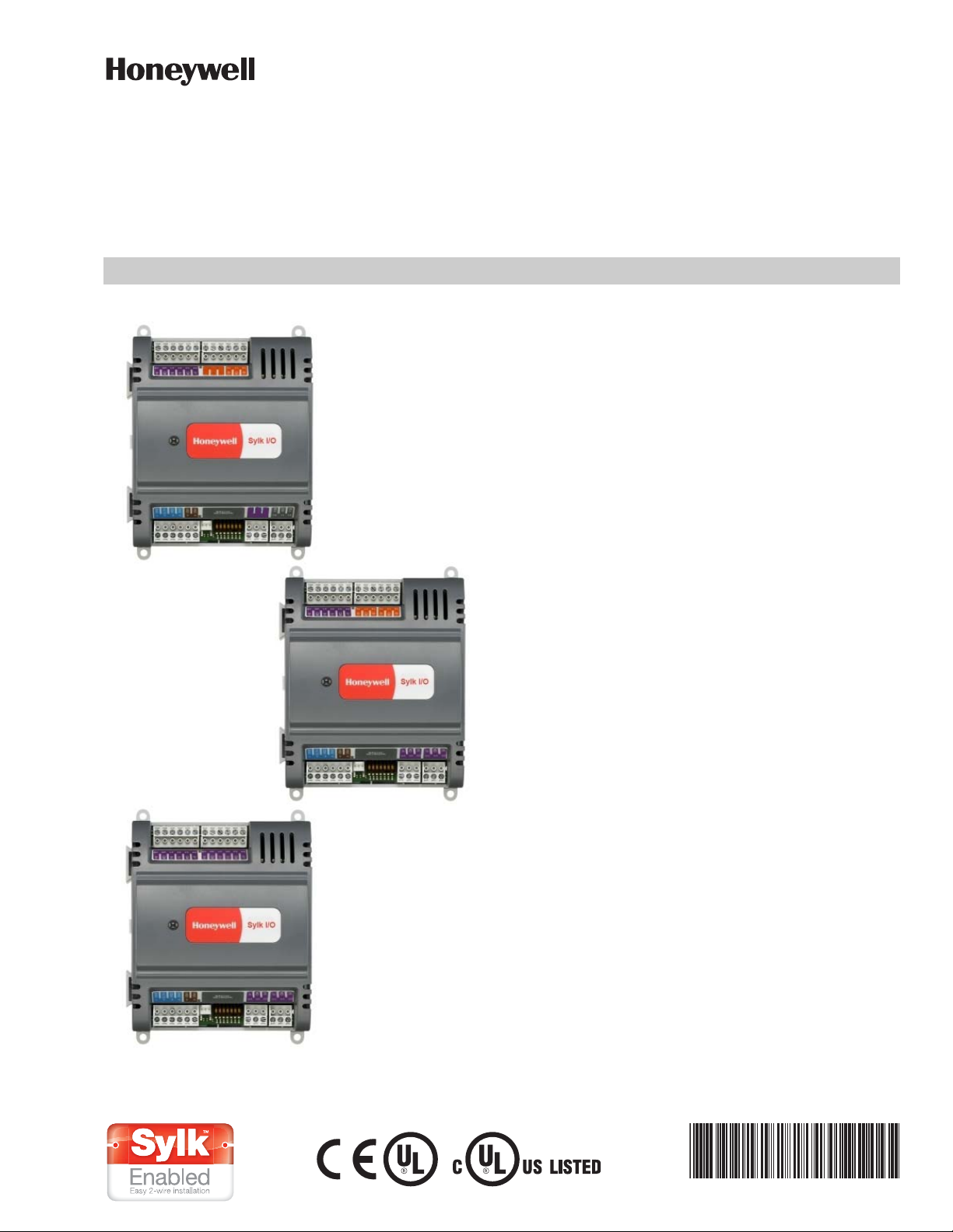
The Sylk IO devices are part of the Spyder family. The three
IO devices are designed to seamlessly integrate with
Spyder with relay controllers using only Sylk™ for
communication. These devices expand the footprint of a
single Spyder, increasing the controller's ability to be
applied in applications that require a large amount of
physical I/O. The Sylk IO devices are programmable using
existing Spyder wire sheets through the Niagara
Framework® software. Since the Sylk IO devices are
extensions of the Spyder LON and Spyder BACnet
controllers, the same Spyder feature will be leveraged in
the WebPro workbench tool and the WEBs-AX JACE
controller. To utilize the Sylk IO devices, the Spyder with
Relay models, PUL6438SR (for LON) or PUB6438SR (for
BACnet), need to be selected.
The Sylk IO devices are intended for use in HVAC
applications that require a programmable controller
where the IO count is more than the full sized Spyder point
count. All devices provide flexible, universal inputs for
external sensors while SIO6042 and SIO4022 provide a
combination of analog and digital outputs.
FEATURES
•Ex
pands a single Spyder controller's IO count by 8-1
IO per device.
• Up to three devices for Lon Spyders and up to two
devices for BACnet Spyders can be applied.
• Communicates through Sylk™ bus freeing up IO for
more applications.
• Program logic resides in a single controller and uses
the existing Spyder wire sheet.
• Programming is built directly into the Spyder tool.
• Installation can be done locally or remotely.
• Field configurable and programmable for control,
input, and output functions using the Niagara
Framework® software.
• All wiring connections are made to removable
terminal blocks to simplify device installation and
replacement.
• The device housing is UL plenum rated.
Contents
Description ............................................................................................ 2
Specifications ...................................................................................... 2
Installation ............................................................................................ 2
Checkout ................................................................................................ 9
Device Replacement ........................................................................ 10
2
Page 2
SYLK™ I/O DEVICES
WARNING
DESCRIPTION
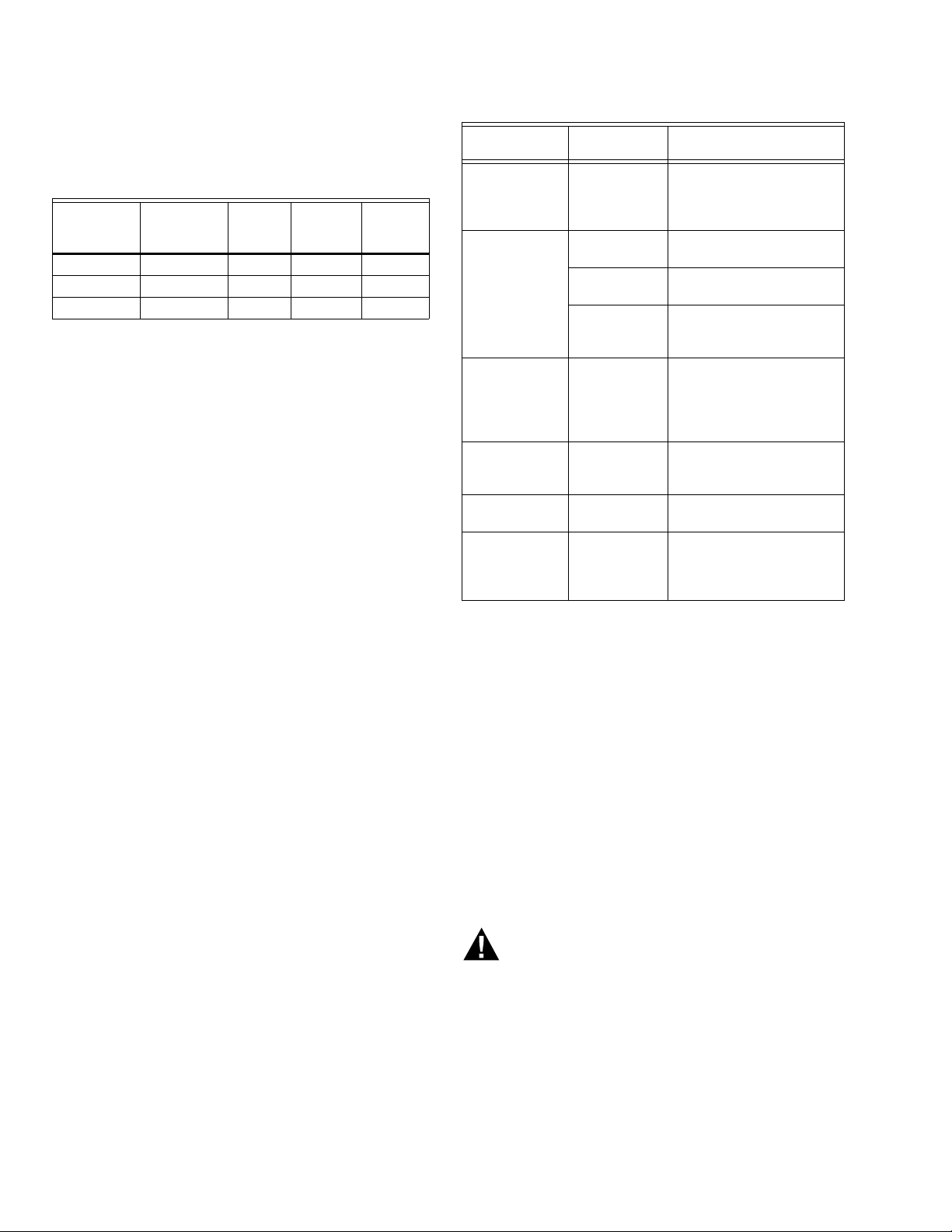
The Sylk IO devices are available in three models, as
described in Table 1.
Table 1. Device Configurations.
UI
(Universal
Devices
SI06042 6 0 4 2
SI04022 4 0 2 2
SI012000 12 0 0 0
Each device is programmable because the user chooses
which function blocks to use and how to connect them. It
is configurable because each function block has userdefined behavior.
Input)
DI
(Digital
Input)
AO
(Analog
Output)
DO
(Digital
Output)
SPECIFICATIONS
General Specifications
Electrical
Rated Voltage: 20-30 Vac; 50/60 Hz
Power Consumption:
100 VA for Sylk IO device and all connected loads
Sylk IO Device Only Load (Excluding Digital Triac Out-
puts): 3 VA maximum (SIO12000), 4 VA maximum
(SIO4022), 5 VA maximum (SIO6042)
Environmental
Operating & Storage Temperature Ambient Rating:
Minimum -40° F (-40° C); Maximum 150° F (65.5° C)
Relative Humidity: 5% to 95% non-condensing
Digital Triac Output (DO) Circuits
Voltage Rating: 20 to 30 Vac @ 50/60Hz
Current Rating: 25 mA to 500 mA continuous, and
800 mA (AC rms) for 60 milliseconds
Analog Output (AO) Circuits
Analog outputs can be individually configured for current
or voltage.
ANALOG CURRENT OUTPUTS:
Current Output Range: 4.0 to 20.0 mA
Output Load Resistance: 550 Ohms maximum
Table 2. Universal Input Circuit Specifications.
Input
Type
Room/Zone
Discharge Air
Outdoor Air
Tem per ature
Outdoor Air
Tem per ature
TR23
Setpoint
Potentiometer
Resistive Input Generic 100 Ohms
Voltage
Input
Discrete Input Dry Contact
a
C7031G and C7041F are recommended for use with
these controllers, due to improved resolution and accuracy when compared to the PT1000.
Sensor
Type
20K Ohm
NTC
C7031G
C7041F
PT1000
(IEC751
3850)
500 Ohm
to
10,500 Ohm
Tra nsduc er,
Controller
closure
a
a
Operating
Range
-40° F to 199° F
(-40° C to 93° C)
-40° to 120°F
(-40° to 49°C)
-40° to 250°F
(-40° to 121°C)
-40° F to 199° F
(-40° C to 93° C)
-4° DDC to 4° DDC
(-8° DDF to 7° DDF)
or
50° F to 90° F
(10° C to 32° C)
to
100K Ohms
0 - 10 Vdc
Open Circuit ≥
3000Ohms
Closed Circuit <
3000Ohms
BEFORE INSTALLATION
The device is available in three models (see Table 1).
Review the power, input, and output specifications on
page 2 before installing the device.
— Hardware driven by Triac outputs must have a
minimum current draw, when energized, of 25 mA and a
maximum current draw of 500 mA.
— Hardware driven by the analog current outputs must
have a maximum resistance of 550 Ohms, resulting in a
maximum voltage of 11 volts when driven at 20 mA. If
resistance exceeds 550 Ohms, voltages up to 18 Vdc
are possible at the analog output terminal.
ANALOG VOLTAGE OUTPUTS:
Voltage Output Range: 0 to 10.0 Vdc
Maximum Output Current: 10.0 mA
Analog outputs may be configured as digital outputs and
operate as follows:
– False (0%) produces 0 Vdc, (0 mA)
– True (100%) produces the maximum 11 Vdc, (22 mA)
Universal Input (UI) Circuits
See Table 2 for the UI circuit specifications.
31-00028—02 2
Electrical Shock Hazard.
Can cause severe injury, death or property
damage.
Disconnect power supply before beginning wiring
or making wiring connections to prevent electrical
shock or equipment damage.
INSTALLATION
The device must be mounted in a position that allows
clearance for wiring, servicing, and removal.
Page 3
SYLK™ I/O DEVICES
M35144
NOTE: DEVICE CAN BE MOUNTED IN ANY ORIENTATION.
3/16 (4.5) PANEL MOUNTING HOLE (4X)
1 1 1 1 1 1 1 2 2 2 2 2
3 4 5 6 7 8 9 0 1 2 3 4
1 1
1 2 3 4 5 6 7 8 9 0 1 2
DEPTH IS
2-1/ 4 (57)
4-13/16 (122)
4-1/8 (105)
6-1/4
(159)
5-7/8
(149)
DIN RAIL
TOP TABS
BOTTOM FLEX
CONNECTORS
M16815
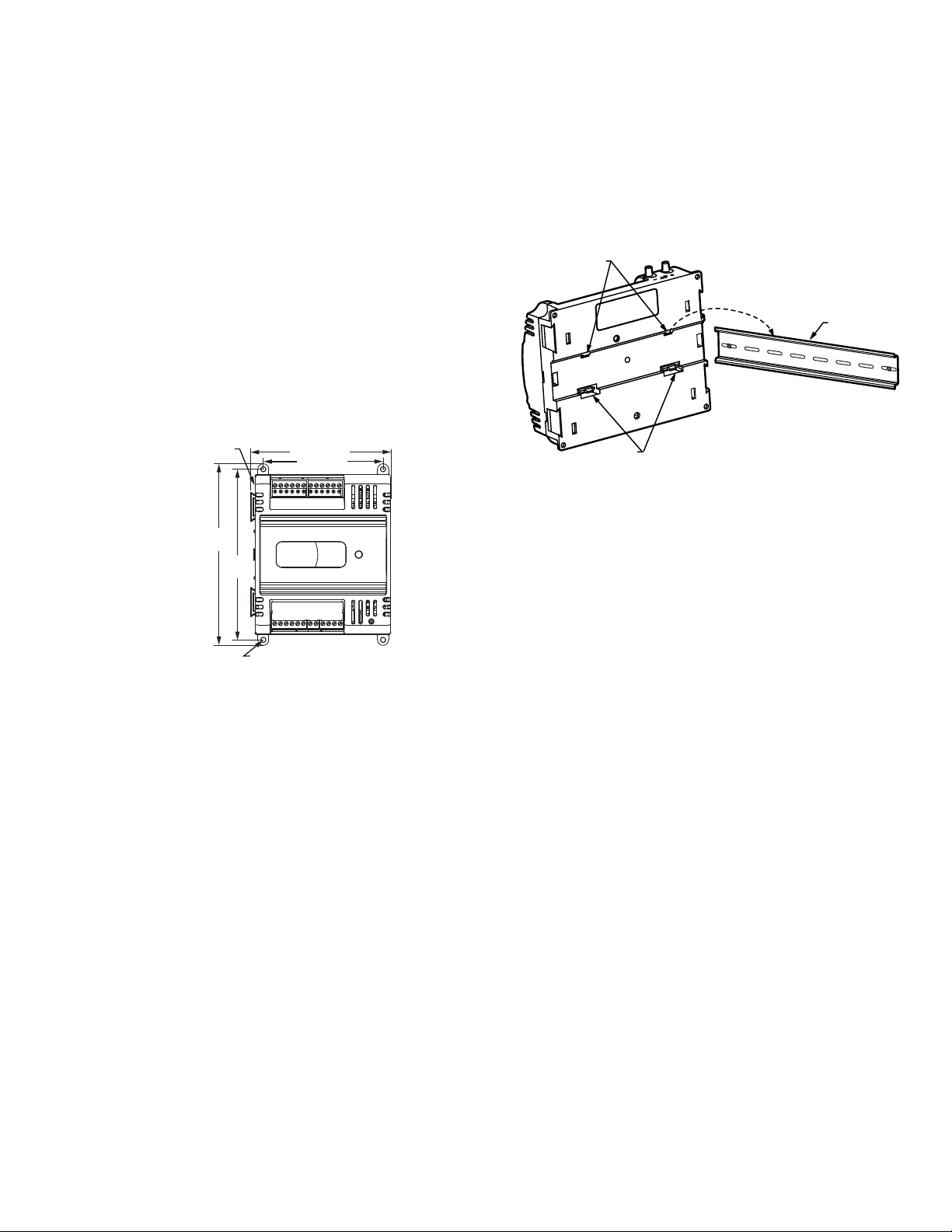
The device may be mounted in any orientation.
IMPORTANT
Avoid mounting in areas where acid fumes or other
deteriorating vapors can attack the metal parts of
the controller, or in areas where escaping gas or
other explosive vapors are present. See Fig. 1 for
mounting dimensions.
Mount Device
NOTE: The device may be wired before mounting to a
panel or DIN rail.
Terminal blocks are used to make all wiring connections to
the device. Attach all wiring to the appropriate terminal
blocks (see “Wiring” on page 5).
See Fig. 1 for panel mounting dimensions. See Fig. 2 on
page 3 for DIN rail mounting.
Fig. 1. Device dimensions in in (mm).
Panel Mounting
The device enclosure is constructed of a plastic base plate
and a plastic factory-snap-on cover.
NOTE: The device is designed so that the cover does not
The device mounts using four screws inserted through the
corners of the base plate. Fasten securely with four No. 6
or No. 8 machine or sheet metal screws.
The device can be mounted in any orientation. Ventilation
openings are designed into the cover to allow proper heat
dissipation, regardless of the mounting orientation.
DIN Rail Mounting
To mount the SIO12000, SIO4022, or SIO6042 device on a
DIN rail [standard EN50022; 1-3/8 in. x 9/32 in. (7.5 mm x
35 mm)], refer to Fig. 2 and perform the following steps:
need to be removed from the base plate for either
mounting or wiring.
1. Holding the device with its top tilted in towards the
DIN rail, hook the two top tabs on the back of the
device onto the top of the DIN rail.
2. Push down and in to snap the two bottom flex connectors of the device onto the DIN rail.
IMPORTANT
To remove the device from the DIN rail, perform
the following:
1. Push straight up from the bottom to release the
top tabs.
2. Rotate the top of the device out towards you and
pull the controller down and away from the DIN rail
to release the bottom flex connectors.
Fig. 2. Controller DIN rail mounting
(models SIO12000, SIO4022, and SIO6042).
Power
Before wiring the controller and device, determine the
input and output device requirements for each controller
and device used in the system. Select input and output
devices compatible with the controller, device, and the
application. Consider the operating range, wiring
requirements, and the environment conditions when
selecting input/output devices. When selecting actuators
for modulating applications consider using floating
control. In direct digital control applications, floating
actuators will generally provide control action equal to or
better than an analog input actuator for lower cost.
Determine the location of controllers, sensors, actuators
and other input/output devices and create wiring diagrams.
The application engineer must review the control job
requirements. This includes the sequences of operation
for the controller, and for the system as a whole. Usually,
there are variables that must be passed between
controllers that are required for optimum system-wide
operation. Typical examples are the TOD, Occ/Unocc
signal, the outdoor air temperature, the demand limit
control signal, and the smoke control mode signal.
It is important to understand these interrelationships
early in the job engineering process, to ensure proper
implementation when configuring the controllers.
Power Budget
A power budget must be calculated for each device to
determine the required transformer size for proper
operation. A power budget is simply the summing of the
maximum power draw ratings (in VA) of all the devices to
be controlled. This includes the controller itself and any
devices powered from the controller, such as equipment
actuators (ML6161 or other motors) and various
contactors and transducers.
3 31-00028—02
Page 4
SYLK™ I/O DEVICES
IMPORTANT
• If a controller is used on Heating and Cooling
Equipment (UL 1995, U.S. only) and transformer
primary power is more than 150 volts, connect the
transformer secondary common to earth ground
(see Fig. 5 on page 6).
• When multiple controllers operate from a single
transformer, connect the same side of the transformer secondary to the same power input terminal in each device. The earth ground terminal
(terminal 3) must be connected to a verified earth
ground for each controller in the group (see Fig. 6
on page 7).
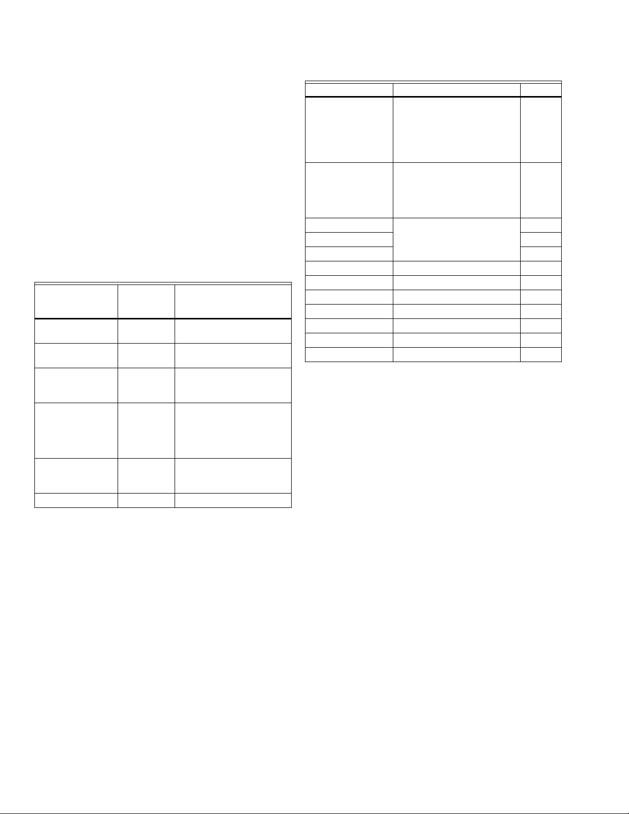
POWER BUDGET CALCULATION EXAMPLE
Table 3 is an example of a power budget calculation for
typical Spyder LON controller and Sylk IO devices. While
the example is shown for only these models, the process is
applicable for all controller and device configurations.
Table 3. Power budget calculation example.
VA
Informatio
Device
nObtained From
PUL6438SR 5.0 Spyder LON Product Data
Sheet
SIO6042
R8242A
Contactor fan
rating
5.0
21.0
a
See “Specifications” on
page 2.
TRADELINE
®
Catalog
inrush rating
D/X Stages 0.0 For example, assume
cooling stage outputs are
wired into a compressor
control circuit and have
no impact on the budget.
M6410A Steam
Heating Coil
Valve
0.7
TRADELINE® Catalog,
0.32A 24 Vac
TOTAL 31.7
a
Excludes the use of digital Triac outputs.
The system example above requires 31.7 VA of peak power.
Therefore, a 100 VA AT92A transformer could be used to
power one controller and device of this type. Because the
total peak power is less than 33 VA, this same transformer
could be used to power this configuration and meet NEC
Class 2 restrictions (no greater than 100 VA).
See Fig. 4–Fig. 6 beginning on page 6 for illustrations of
controller power wiring. See Table 4 for VA ratings of
various devices.
Table 4. VA ratings for transformer sizing.
Device Description VA
PVL0000AS,
PVL4022AS, and
Controller and Actuator
a
9.0
PVL6436AS
controllers and
Series 60 Floating
Damper Actuator
PUL1012S,
PUL4024S,
Controller
a
5.0
PUL6438S,
PVL4024NS, or
PVL6438NS
SIO12000
IO Device
a
3.0
SIO4022 4.0
SIO642 5.0
ML684 Versadrive Valve Actuator 12.0
ML6161 Damper Actuator, 35 lb-in. 2.2
ML6185
Damper Actuator SR 50 lb-in
12.0
ML6464 Damper Actuator, 66 lb-in. 3.0
ML6474 Damper Actuator, 132 lb-in. 3.0
R6410A Valve Actuator 0.7
R8242A Contactor 21.0
a
When used, each digital Triac output can add an addi-
tional 22 VA (peak) and 12 VA long-term.
For contactors and similar devices, the in-rush power ratings
should be used as the worst case values when performing
power budget calculations. Also, the application engineer
must consider the possible combinations of simultaneously
energized outputs and calculate the VA ratings accordingly.
The worst case, which uses the largest possible VA load,
should be determined when sizing the transformer.
Each device requires 24 Vac power from an energy-limited
Class II power source. To conform to Class II restrictions
(U.S. only), transformers must not be larger than 100 VA. A
single transformer can power more than one device.
GUIDELINES FOR POWER WIRING ARE AS FOLLOWS:
— For multiple devices operating from a single trans-
former, the same side of the transformer secondary
must be connected to the same power input terminal in each device. The earth ground terminal must
be connected to a verified earth ground for each
device in the group (see Fig. 6 on page 7). Device
configurations are not necessarily limited to three
devices, but the total power draw, including accessories, cannot exceed 100 VA when powered by the
same transformer (U.S. only).
— See Fig. 5 on page 6 for device power wiring used in
UL 1995 equipment (U.S. only).
— Many devices require all loads to be powered by the
same transformer that powers the device.
— Keep the earth ground connection wire run as short
as possible (refer to Fig. 4–Fig. 6 beginning on
page 6).
— Do not connect earth ground to the device’s digital
or analog ground terminals (refer to Fig. 4 and
Fig. 6).
— Unswitched 24 Vac power wiring can be run in the
same conduit as the L
ONWORKS® Bus cable.
31-00028—02 4
Page 5
SYLK™ I/O DEVICES
Line-Loss
Devices must receive a minimum supply voltage of 20 Vac.
If long power or output wire runs are required, a voltage
drop due to Ohms Law (I x R) line-loss must be considered.
This line-loss can result in a significant increase in total
power required and thereby affect transformer sizing. The
following example is an I x R line-loss calculation for a 200
ft. (61m) run from the transformer to a device drawing 37
VA and using two 18 AWG (1.0 sq mm) wires.
The formula is:
Loss = [length of round-trip wire run (ft.)] x [resistance
in wire (ohms per ft.)] x [current in wire (amperes)]
From specification data:
18 AWG twisted pair wire has a resistance of 6.52 ohms
per 1000 feet.
Loss = [(400 ft.) x (6.52/1000 ohms per ft.)] x [(37
VA)/(24V)] = 4.02 volts
This means that four volts are going to be lost between the
transformer and the device. To assure the device receives
at least 20 volts, the transformer must output more than
24 volts. Because all transformer output voltage levels
depend on the size of the connected load, a larger
transformer outputs a higher voltage than a smaller one
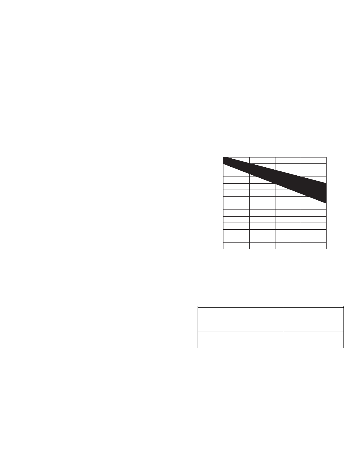
for a given load. Fig. 3 shows this voltage load
dependence.
In the preceding I x R loss example, even though the
device load is only 37 VA, a standard 40 VA transformer is
not sufficient due to the line-loss. Looking at Fig. 3, a 40
VA transformer is just under 100 percent loaded (for the
37 VA controller) and has a secondary voltage of 22.9
volts. (Use the lower edge of the shaded zone in Fig. 3 that
represents the worst case conditions.) When the I x R loss
of four volts is subtracted, only 18.9 volts reaches the
device. This is not enough voltage for proper operation.
In this situation, the engineer has three alternatives:
1. Use a larger transformer. For example, if an 80 VA
model is used, an output of 24.4 volts, minus the
four volt line-loss, supplies 20.4V to the device (see
Fig. 3). Although acceptable, the four-volt line-loss
in this example is higher than recommended.
IMPORTANT
No installation should be designed where the
line-loss is greater than two volts. This allows for
nominal operation if the primary voltage drops to
102 Vac (120 Vac minus 15 percent).
The issue of line-loss is also important in the case of the
output wiring connected to the Triac digital outputs. The
same formula and method are used. Keep all power and
output wire runs as short as practical. When necessary,
use heavier gauge wire, a bigger transformer, or install the
transformer closer to the controller.
To meet the National Electrical Manufacturers Association
(NEMA) standards, a transformer must stay within the
NEMA limits. The chart in Fig. 3 shows the required limits
at various loads.
With 100 percent load, the transformer secondary must
supply between 23 and 25 volts to meet the NEMA
standard. When a purchased transformer meets the
NEMA standard DC20-1986, the transformer voltage
regulating ability can be considered reliable. Compliance
with the NEMA standard is voluntary.
27
26
25
24
23
22
21
20
19
18
SECONDARY VOLTAGE
17
16
15
14
0 50 100 150
% OF LOAD
200
M993
Fig. 3. NEMA Class 2 transformer voltage output limits.
The Honeywell transformers listed in Table 5 meet the
NEMA standard DC20-1986.
Table 5. Honeywell transformers that meet
NEMA standard DC20-1986.
Transformer Type VA Rating
AT40A 40
AT72D 40
AT87A 50
AK3310 Assembly 100
2. Use heavier gauge wire for the power run. 14 AWG
(2.0 sq mm) wire has a resistance of 2.57 ohms per
1,000 ft. Using the preceding formula results in a
line-loss of only 1.58 volts (compared with 4.02
volts). This would allow a 40 VA transformer to be
used. 14 AWG (2.0 sq mm) wire is the recommended
wire size for 24 Vac wiring.
3. Locate the transformer closer to the device. This
reduces the length of the wire run, and the line-loss.
NOTE: The AT88A and AT92A transformers do not meet
the voluntary NEMA standard DC20-1986.
Wiring
All wiring must comply with applicable electrical codes
and ordinances, or as specified on installation wiring
diagrams. Device wiring is terminated to the screw
terminal blocks located on the top and the bottom of the
device.
5 31-00028—02
Page 6
SYLK™ I/O DEVICES
WARNING
A
Electrical Shock Hazard.
Can cause severe injury, death or property
damage.
Disconnect power supply before beginning wiring
or making wiring connections, to prevent electrical
shock or equipment damage.
NOTES:
— For multiple controllers and devices operating
from a single transformer, the same side of the
transformer secondary must be connected to
the same power input terminal in each controller. Controller and device configurations will
not necessarily be limited to three devices, but
the total power draw, including accessories,
cannot exceed 100 VA when powered by the
same transformer (U.S. only). For power and
wiring recommendations, See “Power” on
page 3. The earth ground terminal (terminal 3)
must be connected to a verified earth ground
for each controller or device in the group (see
Fig. 6 on page 7).
— All loads on the controller and device must be
powered by the same transformer that powers
the controller and device themselves. A controller can use separate transformers for controller power and output power.
— Keep the earth ground connection (terminal 3)
wire run as short as possible.
— Do not connect the universal input COM termi-
nals, analog output COM terminals or the digital input/output COM terminals to earth
ground. Refer to Fig. 4–Fig. 6 for wiring exam-
ples.
The 24 Vac power from an energy limited Class II power
source must be provided to the controller and device. To
conform to Class II restrictions (U.S. only), the transformer
must not be larger than 100 VA.
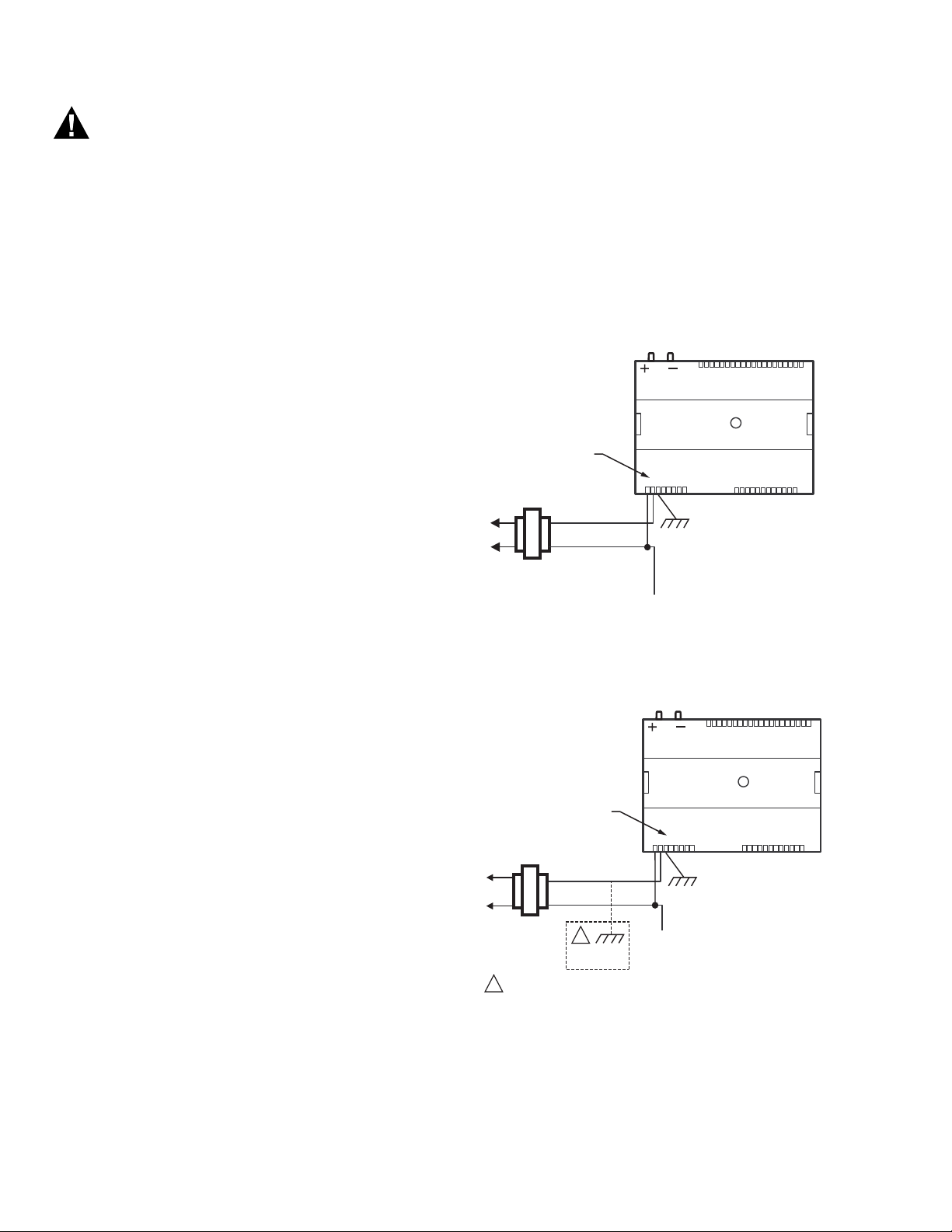
Fig. 4 depicts a single controller using one transformer.
IMPORTANT
If the controller and device are used on Heating
and Cooling Equipment (UL 1995, U.S. only) and
the transformer primary power is more than 150
volts, connect terminal 2, (the 24 Vac common [24
VAC COM] terminal) to earth ground (see Fig. 5).
For these applications, only one controller and
device can be powered by each transformer.
NOTES:
— Unswitched 24 Vac power wiring can be run in
the same conduit as the L
ONWORKS® cable.
— Maintain at least a 3 in. (7.6 cm) separation
between Triac outputs and LONWORKS® wiring
throughout the installation.
Δ
CONNECT POWER TO
TERMINALS 1 AND 2
COM
24 VAC
TRANSFORMER
P
1 2 3 4 5 6
OUTPUT
DEVICE
POWER
2
2 2
1 2 3 4 5 6
7 8
EARTH
GROUND
(TERMINAL 3)
2 2 2 2
2 2 3 3
7 8 0 9
1 1 1 1 1 1 1 1 1 2 1
1 0 9 2 3 4 5 6 7 8 0 9
1 2 3 4 5 6
Fig. 4. Power wiring details for one controller
per transformer.
ΔP
2
2 2 2 2
2 2
1 2 3 4 5 6
7 8 0 9
2 2 3 3
3 3 3
3 3
3 3
3 3 3
3 3
1 2 3 4 5 6
3 4
7 8 0 9
M23557
3 3
3 4
7 8 0 9
IMPORTANT
Power must be off prior to connecting to or removing connections from the 24 Vac power (24
Vac/24 Vac COM), earth ground (EGND), and 20
Vdc power (20 Vdc) terminals.
IMPORTANT
Use the heaviest gauge wire available, up to
14 AWG (2.0 sq mm), with a minimum of 18 AWG
(1.0 sq mm), for all power and earth ground wiring.
Screw-type terminal blocks are designed to accept
up to one 14 AWG (2.0 sq mm) conductor or up to
two 18 AWG (1.0 sq mm) conductors. More than
two wires that are 18 AWG (2.0 sq mm) can be connected with a wire nut. Include a pigtail with this
wire group and attach the pigtail to the terminal
block.
31-00028—02 6
CONNECT POWER TO
TERMINALS 1 AND 2
7 8
1 2 3 4 5 6
TRANSFORMER
COM
24 VAC
LINE VOLTAGE
GREATER
THAN 150 VAC
IF THE CONTROLLER IS USED IN UL 1995 EQUIPMENT AND THE
1
PRIMARY POWER IS MORE THAN 150 VOLTS, GROUND 24 VAC COM
SIDE OF TRANSFORMER SECONDARY.
1
EARTH
GROUND
OUTPUT
DEVICE
POWER
EARTH
GROUND
(TERMINAL 3)
1 1 1 1 1 1 1 1 1 2 1
1 0 9 2 3 4 5 6 7 8 0 9
M23558A
Fig. 5. Transformer power wiring details for one
controller used in UL 1995 equipment (U.S. only).
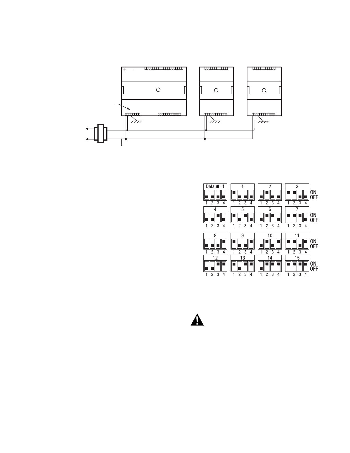
More than one controller and device can be powered by a
single transformer. Fig. 6 shows power wiring details for
multiple controllers.
Page 7
SYLK™ I/O DEVICES
WARNING
M35143
120/240
VAC
TRANSFORMER
OUTPUT
DEVICE
POWER
123456
78
109 2345678 09
11 1111111 21
123456780
9
2222222223
3
123456780
9
333
33
33
34
COM
24 VAC
321 4567890 21
111
345678902
1
1111111222
2
3
4
2
EARTH
GROUND
(TERMINAL 3)
EARTH
GROUND
(TERMINAL 3)
EARTH
GROUND
(TERMINAL 3)
CONNECT POWER TO
TERMINALS 1 AND 2
321 4567890 21
111
345678902
1
1111111222
2
3
4
2
NOTE: Controller and device configurations are not nec-
essarily limited to three devices, but the total
power draw, including accessories, cannot exceed
Fig. 6. Power wiring details for two or more controllers and devices per transformer.
Communications
Sylk™ Bus
Sylk is a two wire, polarity insensitive bus that provides
both 18 VDC power and communications between a Sylkenabled sensor, Sylk-enabled device, and a Sylk-enabled
controller. Using Sylk-enabled sensors and devices saves
I/O on the controller and is faster and cheaper to install
since only two wires are needed and the bus is polarity
insensitive. Sylk sensors and devices are configured using
the latest release of the Spyder Tool for WEBPro and
WEBStation. Using 18 AWG wire, the maximum wire
length for Sylk is 200 ft.
100 VA when powered by the same transformer
(U.S. only). For power wiring recommendations,
see “Power” on page 3.
For Spyders and Sylk IO devices, use the Resource Usage
View in the Spyder tool to determine the maximum
number of devices.
Setting the Device Bus Address Dial
Each device on a Sylk bus must use a different bus
address, and there may be multiple Sylk IOs wired on a
single Sylk bus. To change the bus address of a device,
adjust the address dipswitches to match that of the
desired bus address (1–15). Use the bus address label,
shown in Fig. 7, as a reference. The default address for
Sylk IOs is 1. The address on the device must match the
address in the configuration tool.
M35180
Fig. 7. Bus address settings.
Wiring Method
Electrical Shock Hazard.
Can cause severe injury, death or property
damage.
Disconnect power supply before beginning wiring,
or making wiring connections, to prevent electrical
shock or equipment damage.
7 31-00028—02
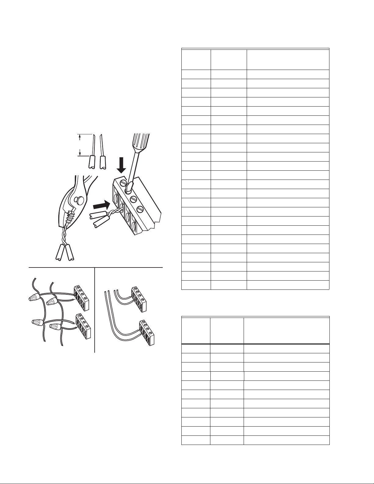
NOTE: When attaching two or more wires to the same
terminal, other than 14 AWG (2.0 sq mm), be
sure to twist them together. Deviation from this
rule can result in improper electrical contact (see
Fig. 8).
Each terminal can accommodate the following gauges of
wire:
— Single wire: from 22 AWG to 14 AWG solid or stranded
Page 8
SYLK™ I/O DEVICES
TO CONTROLLER
DAISY-CHAINING MULTIPLE SYLK IOS HOME RUNNING MULTIPLE SYLK IOS
TO CONTROLLER
TO SYLK IO
M35403
1/2
(13)
STRIP 1/2 IN. (13 MM)
FROM WIRES TO
BE ATTACHED AT
ONE TERMINAL.
1.
2.
TWIST WIRES
TOGETHER WITH
PLIERS (A MINIMUM
OF THREE TURNS).
3.
CUT TWISTED END OF WIRES TO 3/16 IN.
(5 MM) BEFORE INSERTING INTO TERMINAL
AND TIGHTENING SCREW. THEN PULL ON
EACH WIRE IN ALL TERMINALS TO CHECK
FOR GOOD MECHANICAL CONNECTION.
— Multiple wires: up to two 18 AWG stranded, with 1/4
watt wire-wound resistor
Prepare wiring for the terminal blocks, as follows:
1. Strip 1/2 in. (13 mm) insulation from the conductor.
2. Cut a single wire to 3/16 in. (5 mm). Insert the wire in
3. If two or more wires are being inserted into one ter-
4. Cut the twisted end of the wires to 3/16 in. (5 mm)
5. Pull on each wire in all terminals to check for good
the required terminal location and tighten the screw.
minal location, twist the wires together a minimum
of three turns before inserting them (see Fig. 8).
before inserting them into the terminal and tightening the screw.
mechanical connection.
SIO4022
Terminal
s Label Connection
1 24VAC 24VAC Power
2 24VAC COM 24VAC-COMMON
3 EGND Chassis/Earth Ground
4 N/A Not Applicable
5S-BUSSylk
6S-BUSSylk
7 N/A Not Applicable
8 N/A Not Applicable
9 N/A Not Applicable
10 DO-1 Discrete Triac Output
11 COM DO COMMON
12 DO-2 Discrete Triac Output
13 N/A Not Applicable
14 N/A Not Applicable
15 N/A Not Applicable
16 AO-2 Analog Output
17 COM AO COMMON
18 AO-1 Analog Output
19 UI-4 Universal Input
20 COM UI COMMON
21 UI-3 Universal Input
22 UI-2 Universal Input
23 COM UI COMMON
24 UI-1 Universal Input
Fig. 8. Attaching two or more wires at terminal blocks.
Wiring Details
Each device is shipped with the digital outputs, which
switch the 24 Vac to the load (High Side).
The analog outputs (AO) are used to control modulating
heating, cooling and economizer equipment. Any AO may
be used as a digital output, as follows:
— False (0%) produces 0 Vdc, (0 mA)
— True (100%) produces the maximum 11 Vdc (22 mA)
31-00028—02 8
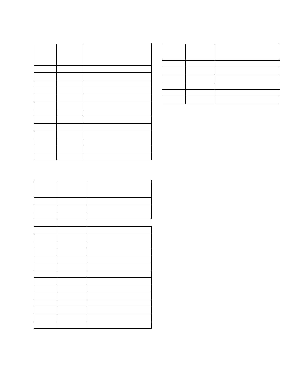
Table 6. Description of wiring terminal connections for
SIO12000.
SIO1200
0
Ter min al
s Label Connection
1 24VAC 24VAC Power
2 24VAC 24VAC-COMMON
3 EGND Chassis/Earth Ground
4 N/A Not Applicable
5S-BUSSylk
6S-BUSSylk
7UI-1Universal Input
8COMUI COMMON
9UI-2Universal Input
10 UI-3 Universal Input
11 COM UI COMMON
Page 9
SYLK™ I/O DEVICES
Table 6. Description of wiring terminal connections for
SIO12000. (Continued)
SIO1200
0
Ter min al
s Label Connection
12 UI-4 Universal Input
13 UI-12 Universal Input
14 COM UI COMMON
15 UI-11 Universal Input
16 UI-10 Universal Input
17 COM UI COMMON
18 UI-9 Universal Input
19 UI-8 Universal Input
20 COM UI COMMON
21 UI-7 Universal Input
22 UI-6 Universal Input
23 COM UI COMMON
24 UI-5 Universal Input
Table 7. Description of wiring terminal connections for
SIO6042.
SIO6042
Terminal
s Label Connection
1 24VAC 24VAC Power
2 24VAC COM 24VAC-COMMON
3 EGND Chassis/Earth Ground
4 N/A Not Applicable
5S-BUSSylk
6S-BUSSylk
7 UI-1 Universal Input
8 COM UI COMMON
9 UI-2 Universal Input
10 DO-1 Discrete Triac Output
11 COM DO COMMON
12 DO-2 Discrete Triac Output
13 AO-4 Analog Output
14 COM AO COMMON
15 AO-3 Analog Output
16 AO-2 Analog Output
17 COM AO COMMON
18 AO-1 Analog Output
Table 7. Description of wiring terminal connections for
SIO6042.
SIO6042
Terminal
s Label Connection
19 UI-6 Universal Input
20 COM UI COMMON
21 UI-5 Universal Input
22 UI-4 Universal Input
23 COM UI COMMON
24 UI-3 Universal Input
IMPORTANT
If the device is not connected to a good earth
ground, the device's internal transient protection
circuitry is compromised and the function of
protecting the device from noise and power line
spikes cannot be fulfilled. This could result in a
damaged circuit board and require replacement of
the device. Refer to installation diagrams for
specific wiring.
CHECKOUT
Step 1. Check Installation and Wiring
Inspect all wiring connections at the device terminals, and
verify compliance with installation wiring diagrams. If any
wiring changes are required, first be sure to remove power
from the controller before starting work. Pay particular
attention to:
— 24 Vac power connections. Verify that multiple devices
being powered by the same transformer are wired with
the transformer secondary connected to the same
input terminal numbers on each device. Use a meter to
measure 24 Vac at the appropriate terminals (see Fig. 6
on page 7). Device configurations are not necessarily
limited to three devices, but the total power draw,
including accessories, cannot exceed 100 VA when
powered by the same transformer (U.S. only).
— Be sure that each device has terminal 3 wired to a
verified earth ground, using a wire run as short as
possible with the heaviest gauge wire available, up to
14 AWG (2.0 sq mm) with a minimum of 18 AWG (1.0 sq
mm) for each controller in the group (see Fig. 6 on
page 7).
— Verify that Triac wiring of the digital outputs to external
devices uses the proper load power and 24 Vac
common terminal (digital output common terminals)
for High-Side switching.
NOTE: All wiring must comply with applicable electrical
codes and ordinances or as specified on installation wiring diagrams.
For guidelines for wiring run lengths and power budget,
see “Power” on page 3.
9 31-00028—02
Page 10
SYLK™ I/O DEVICES
WARNING
WARNING
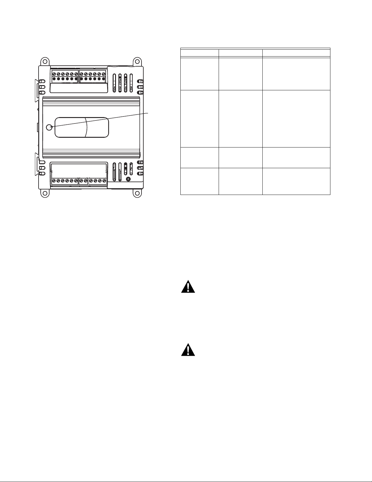
M35135
1 1 1 1 1 1 1 2 2 2 2 2
3 4 5 6 7 8 9 0 1 2 3 4
1 1
1 2 3 4 5 6 7 8 9 0 1 2
LED
Step 2. Startup
LED State Blink Rate Status or Condition
OFF not applicable No power to processor,
ON ON steady;
not blinking
Very Slow
Blink
(continuous)
Slow Blink
(continuous)
1 second ON,
1 second OFF
0.5 second ON,
0.5 second OFF
LED damaged, low
voltage to board, first
second of power up, or
loader damaged.
Processor not operating.
Application Program
CRC being checked. This
takes 1-2 seconds and
occurs on each restart
(power up, reset and
reflash, and following
configuration file
download).
Device is operating
normally.
Device alarm is active or
device in process of
configuration file
download.
Fig. 9. LED, service pin, and network
connection locations.
DEVICE STATUS LED:
The LED on the front of the device provides a visual
indication of the status of the device. When the device
receives power, the LED appears in one of the following
allowable states, as described in Table 3.
Step 3. Checkout Completion
At this point the device is installed and powered. To
complete the checkout, the N
application (run on a PC) is used to configure the I/O and
functions of the controller and device.
IAGARA FRAMEWORK®
DEVICE REPLACEMENT
There are no serviceable or repairable parts inside the
device.
Fire, Explosion, or Electrical Shock Hazard.
Can cause severe injury, death or property
damage.
Do not attempt to modify the physical or electrical
characteristics of this device in any way. Replace
the device if troubleshooting indicates a
malfunction.
Electrical Shock Hazard.
Can cause severe injury, death or property
damage.
Disconnect power supply before beginning device
replacement to prevent electrical shock or
equipment damage.
31-00028—02 10
Terminal Block Removal
To simplify device replacement, all terminal blocks are
designed to be removed with the wiring connections intact
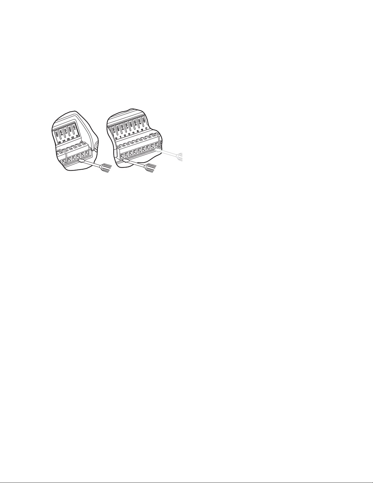
and then re-installed on the new device. See Fig. 10 and
refer to the following procedure:
Page 11
SYLK™ I/O DEVICES
SHORT TERMINAL BLOCK
LONGTERMINAL BLOCK
M23563
IMPORTANT
To prevent bending or breaking the alignment pins
on longer terminal blocks, insert the screwdriver at
several points to evenly and gradually lift up the
terminal block.
Insert the screwdriver blade no more than 1/8 in.
(3 mm) to prevent damage to the terminal block
alignment pins on the device circuit board.
Fig. 10. Removing Terminal Blocks.
1. Use a thin-bladed screwdriver to evenly raise the ter-
minal block from its alignment pins:
a. For short terminal blocks (1 to 5 terminals),
insert screwdriver blade in the center of the terminal block and use a back and forth twisting
motion to gently raise the terminal block from its
alignment pins 1/4 in. (6.35 mm).
b. For long terminal blocks (6 or more terminals),
insert screwdriver blade on one side of the terminal block and gently rotate the blade 1/4 turn.
Then, move to the other side of the terminal
block and do the same. Repeat until the terminal
block is evenly raised 1/4 in. (6.35 mm) from its
alignment pins.
2. Once the terminal block is raised 1/4 in. (6.35 mm)
from its alignment pins, grasp the terminal block at
its center (for long terminal blocks grasp it at each
end) and pull it straight up.
Device Replacement (SIO12000, SIO4022, and SIO6042)
Perform the following to replace the SIO12000, SIO4022,
and SIO6042 devices:
1. Remove all power from the device.
2. Remove the terminal blocks (See “Terminal Block
Removal” on page 10.).
3. Remove the old device from its mounting.
IMPORTANT
(FOR DEVICES MOUNTED TO A DIN RAIL):
1. Push straight up from the bottom to release the
top pins.
2. Rotate the top of the device outwards to release
the bottom flex connectors (see Fig. 2 on page 3).
4. Mount the new device (See “Installation” on page 2.).
5. Replace the terminal blocks:
• Insert each terminal block onto its alignment
pins.
• Press straight down to firmly seat it.
• Repeat for each terminal block.
6. Restore power to the device.
7. Perform “Checkout” on page 9.
11 31-00028—02
Page 12

SYLK™ I/O DEVICES
By using this Honeywell literature, you agree that Honeywell will have no liability for any damages arising out of your use or
modification to, the literature. You will defend and indemnify Honeywell, its affiliates and subsidiaries, from and against any
liability, cost, or damages, including attorneys’ fees, arising out of, or resulting from, any modification to the literature by you.
Home and Building Technologies
In the U.S.:
Honeywell
1985 Douglas Drive North
Golden Valley, MN 55422-3992
customer.honeywell.com
® U.S. Registered Trademark
© 2017 Honeywell International Inc.
31-00028—02 M.S. Rev. 01-17
Printed in United States
 Loading...