

Page 1
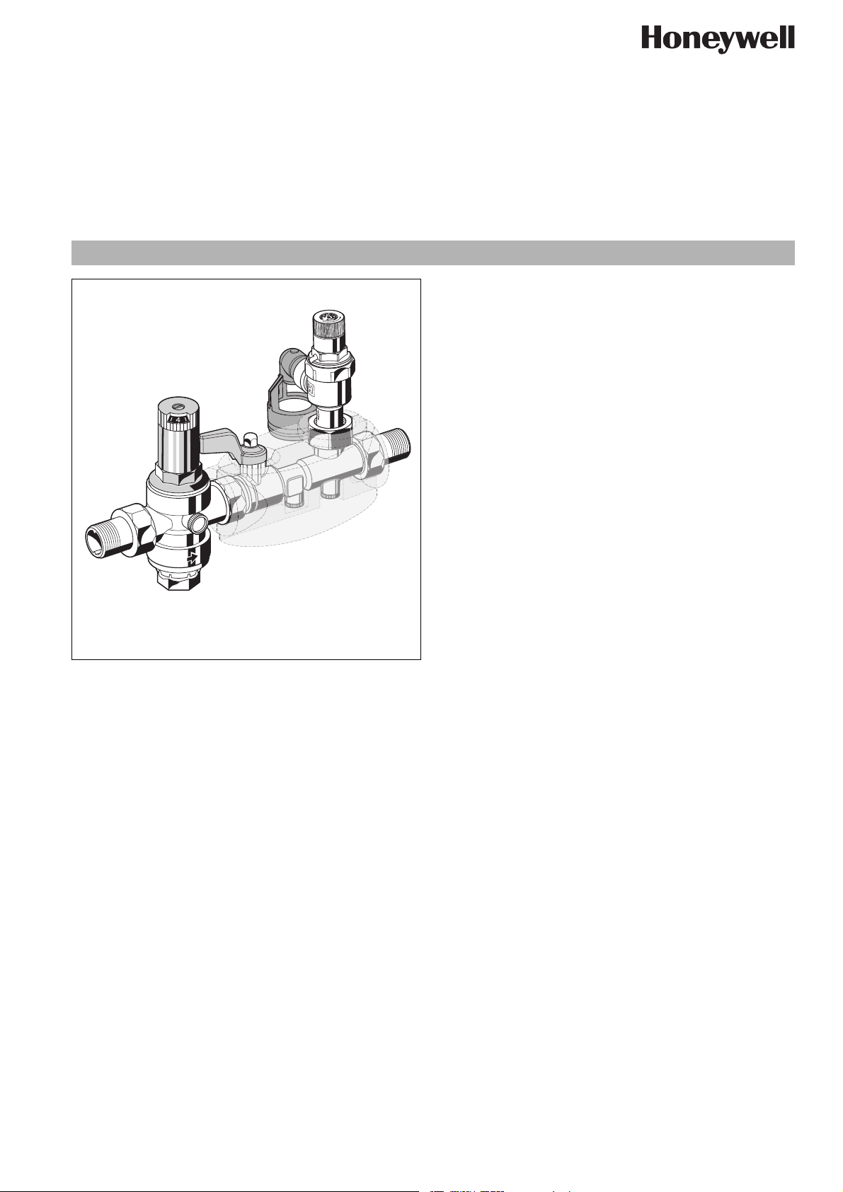
Safety group with interchangeable safety valve insert
Construction
The safety group comprises:
• Housing with test socket G
• Connections (versions AA, AB and AC)
• Shutoff valve
• Complete pressure reducing valve with fine 0.16 mm mesh
filter and transparent filter bowl
• Check valve cartridge
• Approved safety valve exchange insert
• Drain connector
• Insulation shells
• Pressure gauge optional
Materials
• Dezincification resistant brass housing
• Brass threaded connections
• Stainless steel filter mesh on pressure reducing valve
• Transparent synthetic material filter bowl on pressure redu-
EN0H-1356GE23 R1007 • Subject to change
cing valve
• High grade synthetic material pressure reducing valve insert,
spring bonnet with adjuster knob, shutoff valves, test socket,
check valve, safety valve insert and drain connector
• Fibre-reinforced NBR diaphragm
• NBR seals
• EPP insulation shells
1
/4"
SG150D
and pressure reducing valve
Product specification sheet
Application
Safety groups of this type are used to protect pressurised water
heaters according to the requirements of DIN 4753, Part 1,
DIN 1988 and DIN EN1488.
They are compact appliances which incorporate all the necessary
safety devices such as check valve, shutoff valve, test point,
diaphragm type safety valve and pressure reducing valve in one
unit.
The safety valve protects the downstream cylinder, pressure
vessel etc. by automatically opening when excess pressure
occurs. The check valve prevents back pressure, backflow and
back syphonage of water from the hot water unit.
In addition, a balanced seat pressure reducing valve is fitted on
the inlet to control the supply pressure to that required for the
system.
Special Features
• DVGW-approval requested
• Fully approved for noise level protection to class 1
• Replacement insert tested to TRD 721
• Pressure reducing valve with inlet pressure balancing - inlet
pressure fluctuation does not influence the outlet pressure
• Easy venting
• Meets KTW recommendations for potable water
Range of Application
For closed hot water storage units up to 200 litres according to
DIN 4753 Part 1 and DIN 1988. Tested to TRD 721 for 1.0 to 10.0
bar pressure range.
Medium Water
Inlet pressure Max. 16 bar
Outlet pressure 1.5 - 6 bar
Operating pressure Maximum at least below 20 % opening
pressure of safety
Technical Data
Installation position Horizontal and vertical
Opening pressure Set by manufacturer at 6.0, 8.0 or 10.0 bar
Subsequent alteration of the setting is not
permitted and is impossible without
destroying the security cap
Operating temperature
Minimum pressure
drop
Connection size
Max. 40 °C
1 bar
1
/2" + 3/4"
www.honeywell.com 1
Page 2
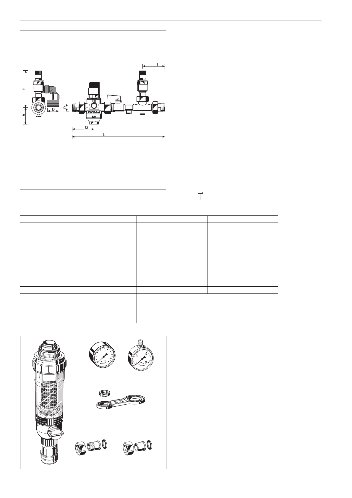
SG150D Safety group with interchangeable safety valve insert
Method of Operation
Safety groups of this type combine pressure reducing valve,
check valve, shutoff valve, test point and diaphragm type safety
valves in one appliance.
Flow first passes through the pressure reducing valve which
operates on a force equalising system whereby the force of a
diaphragm operates against the force of an adjustment spring.
The inlet pressure has no influence on either opening or closing
of the valve and therefore inlet pressure fluctuations have no
influence on the outlet pressure. The check valve has a movable
valve disc which pushes against a spring when flow occurs.
The downstream safety valve is a direct operating safety valve.
That is, the opening force operates against the force of a spring.
The shutoff valve enable the check valve to be checked and
serviced.
Options
SG150D- ... AA = With threaded male connections, 6.0 bar
SG150D- ... AB = With threaded male connections, 8.0 bar
SG150D- ... AC = With threaded male connections, 10.0 bar
SG150D- ... EA = Without fittings, set pressure 6.0 bar
SG150D- ... EB = Without fittings, set pressure 8.0 bar
SG150D- ... EC = Without fittings, set pressure 10.0 bar
Connection size
Connection size R
Weight Version A
Version E
approx.
kg
1
/2"
1.2
1.05
3
1.5
1.27
Funnel outside-ø (mm) D 40 40
Dimensions (mm)
L
l
1
l
2
H
h
247
55
68
124
58
278
67
77
132
58
For water heaters with capacity (litres) 200 200
Safety valve
Approval numbers
TÜV · SV · ..* - 700 · (
TÜV · SV · ..* - 617 · (
1
/2", 3/4") · W · p (6 bar)
1
/2", 3/4") · W · p (8, 10 bar)
DIN/DVGW Approval No. for SG150 requested
DIN/DVGW Approval No. for D06F DW-6330 AT 2314
..* valid Approval No.
Accessories
4
2
r
ba
0
M07M
6
8
10
M08M
FN09S HABEDO ® Retrofit filter
Reverse-rinsing filter for retro-conversion to a filter
combination unit of pressure reducing valves
M07M Pressure gauge
Housing diameter 63 mm, rear connection thread
1
G
/4". Ranges: 0 - 4, 0 - 10, 0 - 16 or 0 - 25 bar.
Please indicate upper value of pressure range when
ordering
ZR06K
M08M Pressure gauge
Housing ∅ 50 mm, connecting pin above G
Partition: 0-16 bar
ZR06K Double ring wrench
For removal of spring bonnet and filter bowl
VST06-A Connection set
VST06-A
VST06-B
Threaded connections
VST06-B Connection set
2 www.honeywell.com
Solder connections
/4"
1
/4"
EN0H-1356GE23 R1007 • Subject to change
Page 3
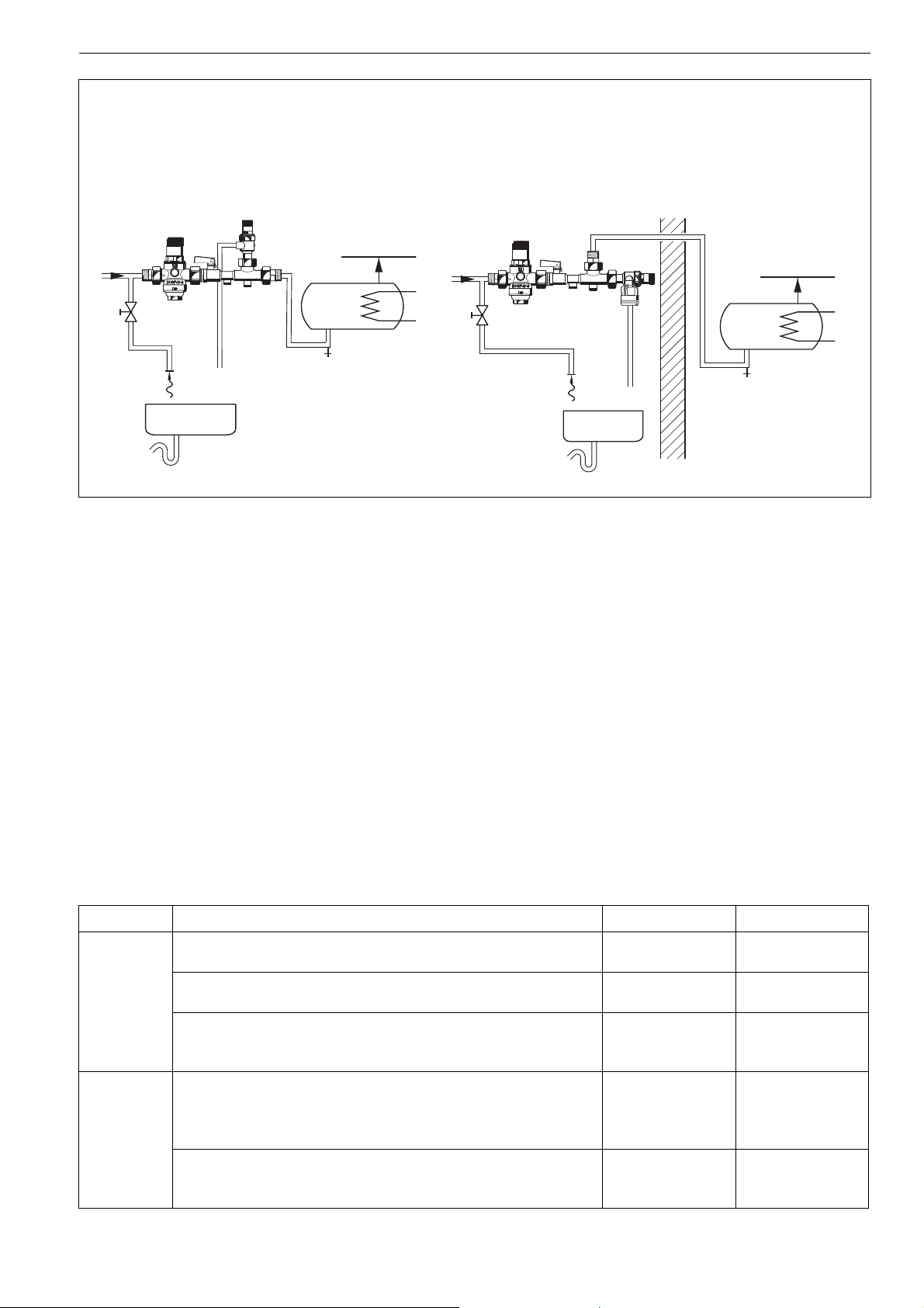
Installation Example
SG150D Safety group with interchangeable safety valve insert
Arrangement of the safety group as channel design
Arrangement of the safety group as corner design
Installation Guidelines
• Safety group must be fitted in the cold water supply to the hot
water storage unit
• Installation in horizontal or vertical pipeline possible
• The installation must be carried out so that:
o There are no shutoff valves or fittings, narrowing of the
pipework or strainers between the water heater and the
safety valve
o Good access is provided for service and maintenance
o The safety valve is fitted above the top of the water heater
to avoid the need for draining down when exchanging the
safety valve insert
• If there is no drainage facility in the room where the heater is
installed, then the safety valve may be fitted in an adjacent
area. DIN 1988, part 2 is to be observed
Typical Applications
Safety groups of this type are installed in accordance with their
specification upstream of water heaters.
The pressure reducing valve is necessary:
• If the inlet pressure is greater than 80% of the safety valve set
opening pressure
The following are some typical applications:
• Central hot water supply systems
• Hot water storage units
Maintenance
In accordance with DIN 1988, Part 8, the following operations should be carried out regularly. A planned maintenance scheme is
recommended.
Operation Interval Carried out by
Inspection Pressure reducing valve: Visual inspection on pressure gauge of the set
Annually User or specialist
outlet pressure at zero flow and at peak flow (large take off).
Check valve: Check operation by opening the test point and closing the
Annually User
lower shutoff valve.
Safety valve: Check operation as follows: With the system operating,
Every six months User or specialist
open the venting device. The resulting water flow must fully drain away.
When the ventil is released,the valve must fully close.
Maintenance Pressure reducing valve: If no stable outlet pressure can be established
at zero flow during the visual inspection, the pressure reducing valve
EN0H-1356GE23 R1007 • Subject to change
insert should be removed for checking and if necessary be replaced.
Every 1 to 3 years
depending on
system operating
Specialist
conditions
Safety valve: If a malfunction occurs,this may be cured by repeated
Annually Specialist
manual opening and closing of the valve. If this method does not
succeed, then an overhaul of the valve will be necessary.
www.honeywell.com 3
Page 4
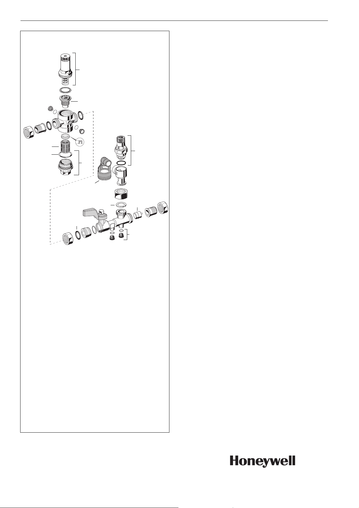
SG150D Safety group with interchangeable safety valve insert
Spare Parts
Safety group SG150D, from 2007 onwards
No. Description Dimension Part No.
6
7
1 Safety valve
exchange insert
Approval No. - TÜV · SV · ..* - 617 Approval No. - TÜV · SV · ..* - 700 6 bar
8 bar
10 bar
1
/2" A152-1/2AA
3
/4" A152-3/4AA
1
/2" A152-1/2AB
3
/4" A152-3/4AB
1
/2" A152-1/2AC
3
/4" A152-3/4AC
1
/2"+3/4"·W·p
1
/2"+3/4"·W·p
..* valid approval No.
8
9
1
10
2 Blanking plug
with O-ring R
(5 pcs.)
1
/4"
S06K-1/4
3 Discharge tundish TA160S
3
5
4
4 Check valve insert
5 Sealing ring
(10 pcs.)
5
6 Spring bonnet
1
/2" 2166200
3
/4" 2110200
1
/2" 0901443
3
/4" 0901444
1
/2" + 3/4" 0901515
complete with setting
2
scale
7 Valve insert complete
1
/2" + 3/4"D06FA-1/2
(without filter)
8 Replacement filter
9 O-ring (10 pcs.)
10 Filter bowl
1
/2" + 3/4" ES06F-1/2A
1
/2" + 3/4" 0901246
1
/2" + 3/4" SK06TG-1/2
Automation and Control Solutions
Honeywell GmbH
Hardhofweg
D-74821 Mosbach
Phone: (49) 6261 810
Fax: (49) 6261 81309
http://europe.hbc.honeywell.com
www.honeywell.com
Manufactured for and on behalf of the
Environmental and Combustion Controls Division
of Honeywell Technologies Sàrl, Ecublens, Route
du Bois 37, Switzerland by its Authorised Representative Honeywell GmbH
EN0H-1356GE23 R1007
Subject to change without notice
© 2007 Honeywell GmbH
 Loading...