

Honeywell S702, S702HF, S702PF, S702HFPF, S706 User Manual
...
Put Bar Code Here
Honeywell Model 700/800 Signal
Contents
Application ....................................................................... 1
Features ........................................................................... 1
Specifications ................................................................... 3
Approvals ......................................................................... 3
Installation ........................................................................ 3
Operation ......................................................................... 11
Modbus Communication .................................................. 16
Troubleshooting ................................................................ 19
Maintenance .................................................................... 19
Safety Manual: 700 Signal Processor .............................. 35
Safety Manual: 70X & 80X Viewing Head ........................ 38
Processor and Viewing Head
USER MANUAL
The two Model 700 signal processors are similar, with 12
push-buttons, a two-digit numeric display, and four LED status
indicators for operator interface. The only difference between
the two is that one accepts AC power and the other accepts
DC power. Both models also accept 24VDC backup power.
Most of the signal processor connections are made through
Phoenix plug-in connectors. Communication connections are
made through modular phone jacks located at the top of the
signal processors (Fig. 7).
Both signal processor models mount on a standard 35 mm
DIN rail. They snap into place and may be released from the
rail using a flat screwdriver.
There are two types of viewing heads—IR/flicker-sensitive and
UV-sensitive—with various features offered resulting in ten
different models. See Table 1 on page 2 for details.
The S702 and S706 viewing head housings are larger in
diameter than the S80X series, are made of aluminum, and
are secured with over-center latches to their mounting blocks
(Fig. 8). In contrast, the S802 and S806 viewing head
housings are smaller in diameter and are made of stainless
steel (Fig. 9). An 800 series viewing head is secured in its
mounting block by a friction twist-lock.
APPLICATION
The Honeywell Model 700ACSP and Model 700DCSP signal
processors are single-channel, fail safe, flame monitoring
systems when used In conjunction with the S70X/S80X
viewing heads. They offer easy setup, excellent discrimination,
and high reliability.
FEATURES
Viewing heads are interchangeable between the two signal
processor models. Any viewing head in the two families will
work with any of the signal processors.
Two signal processor models are available:
• Model 700ACSP Universal 85-265 VAC powered
• Model 700DCSP 22-26VDC powered
The IR/flicker sensitive viewing heads have a high-pass filter
that passes flicker frequencies above 33 Hz. Some models
have a built-in high pass filter that only passes frequencies
above 155 Hz. The high frequency filter models are identified
by adding “HF” to the model number. The UV models respond
to the absolute level of UV radiation—not UV flicker—so there
is no filter option.
66-2069-01

HONEYWELL MODEL 700/800 SIGNAL PROCESSOR AND VIEWING HEAD
The standard electrical connector supplied with both the 700
and 800 viewing head models has two indicator LEDs inside
it: the green LED indicates signal pulses (helpful in
alignment), and the orange LED indicates self-check activity
between the signal processor and the viewing head (Fig. 4).
The green LED also flashes once per second when the
orange LED is pulsed as the viewing head sends an ID code
back to the signal processor.
Model 700 viewing heads are also available with a 1/2 in. pipe
fitting for connecting to electrical conduits. The four
connecting wires exit through an epoxy seal in the 1/2 in. pipe
fitting. The LED indicators are not present in the pipe-fitting
option. The pipe fitting models are identified by adding "PF" to
the model number.
The available models are shown in Table 1.
Table 1. Available viewing head models and associated features.
High
Frequency
Filter 155Hz
Aluminum
Housing
Stainless Steel
Housing
Model Connector
Pipe Fit Connection ½ in
NPTM with 10-ft (3.0m)
pigtail
UVTron
Sensor IR Sensor
S702 X X X
S702HF X X X X
S702PF X X X
S702HFPF X X X X
S706 X X X
S706PF X X X
S706PF-050* X X X
S802 X X X
S802HF X X X X
S806 X X X
*S706PF-050 has a 50-ft (15 m) pigtail
All models include the following:
1. Electronic check (no mechanical shutter) for self-check of the system.
2. All IR viewing heads respond to flicker frequencies above 33Hz, with exception of the HF versions, which only respond to
flicker frequencies above 155 Hz.
The viewing heads, the viewing head connector, and the cable
provided are watertight, and have NEMA 4 and 4X ratings
when the connector is properly tightened with pliers and the
cable is protected from UV exposure.
The availability of both UV-sensing and IR/flicker-sensing
viewing heads ensures that the flame monitoring systems can
provide good discrimination in virtually any application. UV
sensing is appropriate for monitoring natural gas, some mixed
gases and light oil flames. IR/ flicker sensing is appropriate for
monitoring heavy oil and coal flames.
66-2069—01 2

SPECIFICATIONS
HONEYWELL MODEL 700/800 SIGNAL PROCESSOR AND VIEWING HEAD
Series 700 and 800 Viewing Heads
MODELS S702, S702PF, S702HF, S702HFPF, S706,
S706PF, AND MODELS S802, S802HF, AND S806
Electrical
Input Power: 22VDC to 26VDC, 150 mA MAX from Model
700ACSP or 700DCSP Signal Processor
Environmental
Viewing Head Sealing: NEMA TYPE 4/4X rated when the
molded connector ring is tightened with pliers and a UV
protection is provided for the cable by installing in conduit.
Ambient Temperature: -40°F to 185°F (-40°C to 85°C)
IR Detector Spec
S702, S702PF, S702HF, S702HFPF, S802, S802HF:
Germanium photodiode with spectral response 950nm to
1710nm (1/2 intensity points) and peak spectral response
at 1400nm
High Pass Filter Pickup: 33 Hz standard, 155 Hz high
frequency option (-HF)
IR Optical
Angle of View: 1 degree (1.45” dia. at 6 ft. or 3.7cm dia. at
1.8m)
UV Detector Spec
S706 & S706PF, S806: UVtron with spectral response 185nm
to 260nm and a peak response at 210nm
UV Optical
Angle of View: 5 degrees (1 inch per foot)
Cable & Connector
Signal Proc. to V.H.:
(Standard) Honeywell C330, 4 Conductor, 18 ga., shielded,
90C, Sunlight Resistant, 15 ft. long, with ITC rating for US
and CIC rating for Canada. (This rating permits use in
hazardous locations without a conduit.)
With PF option Honeywell C330 cable or 4 conductor, 22
ga. or larger with overall braided shield, 95% coverage, or
with shield over the signal line may be used for extension
purposes. Tie shield to ground at viewhead end and signal
processor end of cable. (Cable must be protected by a
conduit in hazardous locations.)
Dimensions
Refer to Fig. 8 and Fig. 9.
Model 700ACSP & Model 700DCSP Signal
Processer
Electrical: Model 700ACSP
Primary Input Power: 85-265VAC, 50-60 HZ, 0.07A Max.
fused (with either V.H. connected)
Battery Backup Voltage: 22VDC to 26VDC, 0.2A DC Max.
fused (with either V.H. connected)
Electrical: Model 700DCSP
Primary Input Power: 22VDC to 26VDC, 250 mA Max. fused
(with either V.H. connected)
Battery Backup Voltage: 22VDC to 26VDC, 0.5A DC Max.,
fused (with either V.H. connected)
Outputs
Flame Relay: 2 form C contacts
Self-Checking Relay: 1 form C contact
Relay Contact Ratings: 5A at 125 VAC, 277 VAC, & 30 VDC;
1/8 HP 125 & 250 VAC
Analog Flame Signal: Isolated 0 to 20 mA or 4 to 20 mA
output for remote meters or DCS, 360 ohms maximum
resistance
Environmental
Ambient Temperature: 32°F to 140°F (0°C to 60°C)
Dimensions
Refer to Fig. 10 and Fig. 11.
APPROVALS
S70X/S80X Viewing Heads (Connector series and Pipe fit
series [PF])
CSA for CLASS I, DIV 2, GROUPS A, B, C, D & T4A
FM 7610/NEMA 4X and CLASS 1, DIV 2, GROUPS A, B, C, D
& T4A*
SIL 3 “Fit for Use”
IECEx CSA 10.0003 Ex nA IIC T4 Gc
-40<Ta<85ºC, -40<TA<185ºF
*IP67/NEMA 4/4X rating applies when connector ring is
properly tightened and cable is UV shielded
700ACSP and 700DCSP Signal Processors
CSA (C, US)
FM
INSTALLATION
When Installing These Products...
1. Read these instructions carefully. Failure to follow them
could damage the products or cause a hazardous
condition.
2. Check the ratings given in the instructions and one the
products to make sure the products are suitable for your
application.
3. Installer must be a trained, experienced, flame
safeguard control technician.
4. After installation is complete, check out product
operation as provided in these instructions.
Signal Processor Mounting
The 700ACSP and 700DCSP signal processors mount on a
standard 35mm DIN rail. They snap into place and may be
released from the rail using a flat screwdriver.
3 66-2069—01

HONEYWELL MODEL 700/800 SIGNAL PROCESSOR AND VIEWING HEAD
Grounding and Shielding
NOTE: Installer must be a trained, experienced flame
safeguard service technician and should be
familiar with the equipment operation and
limitations and be aware of any applicable local
codes and regulations.
1. Connect a safety ground to the viewing head housing (if
applicable).
2. The viewing head and all associated cable/conduit must
be at least 12 inches (31 cm) from any source of high
energy or voltage (for example, igniter equipment).
3. Install a ground wire from the ignition transformer case
to the igniter assembly.
4. Ensure all igniter wires and cables show no signs of
wear. Replace any igniter cables or wires that are frayed
or cracked.
5. The viewing head must be electrically isolated from the
burner front.
a. Electrical isolation can be accomplished by
installing an Ultem nipple (R-518-13) or an Ultem
locking coupler adapter (R-518-PT13 or R-518PT13L) in conjunction with a locking coupler (R-518CL13-HTG) between the viewing head flange and
the burner mount.
b. The purge air line should also be isolated from the
viewing head. This can be accomplished by
installing any insulating material, for example a
rubber hose, in between the purge air line and the
viewing head.
Signal Processor Power Connections
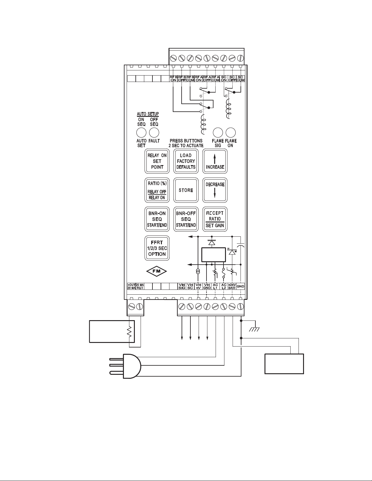
The Model 700ACSP power and relay connections are shown
in Fig. 1. The AC power supply to the 700ACSP Signal
Processor passes through a 2A fuse and an inrush current
limiter.
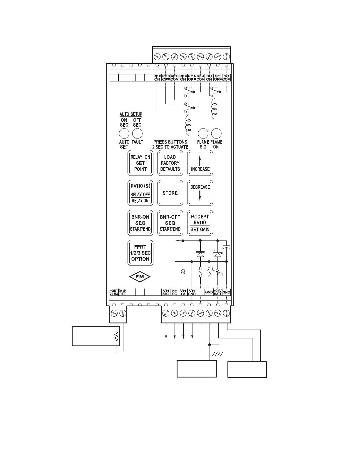
The Model 700DCSP power and relay connections are shown
in Fig. 2. The maximum current rating for each 700DCSP is
250mA.
In the Model 700 signal processors the flame relay (RF A/B
ON, OFF, COM) has two sets of FORM C (SPDT) contacts
and the self-check relay (SC ON, OFF, COM) has one set (Fig.
1 and Fig. 2). The self-check relay is energized whenever the
signal processor is powered and is operating normally,
whether the flame relay is energized or not. Internally, the
flame relay is wired in series with the self-check relay (not
shown), which prevents the flame relay from energizing if the
self-check relay is not energized.
Unique fail-safe circuitry for the self-check and flame relays
ensure that in the event of any critical component failure
occurrence, system response will be to de-energize the selfcheck relay, which in turn de-energizes the flame relay.
Some of the internal power wiring of the Model 700ACSP and
Model 700DCSP signal processors is shown in Fig. 1 and
Fig. 2. Rectifier diodes separate the battery backup input from
the main power bus until the battery voltage exceeds the
internal DC voltage plus a diode voltage drop. Resettable
fuses (shown as resistors with slashes) and conventional
fuses prevent internal failures from loading the power sources.
With the Model 700DCSP, if a backup battery is to be used
with a main power supply, the two power sources would be
wired as shown in Fig. 2. If no backup battery is to be
installed, the main power supply can be connected at +26V
PWR and GND as shown in Fig. 2 or it can be connected to
the +24V BATT input and GND. It is preferable to use the
battery connections because it takes advantage of the
resettable fuse at the battery input; resettable fuses recover
automatically from a fault within a few seconds after power is
removed. At the +26V PWR input and its associated GND,
conventional1A fuses are used because they are able to
protect against 240VAC being applied by accident (this could
happen if a Model 700DCSP is installed in a cabinet wired for
a Model 700ACSP).
66-2069—01 4
HONEYWELL MODEL 700/800 SIGNAL PROCESSOR AND VIEWING HEAD
APPROVED
AC IN
GROUND
TO VIEWING
HEAD
24 V
BACKUP BATTERY
(OPTIONAL)
0-20 OR 4-20 MA
FOR INDICATOR OR
INSTRUMENTATION
360 OHMS MAX
+
-
+
-
CHASSIS,
EARTH, OR
SYSTEM GND
M34280
+
+26VDC
GND
.125 A
.4A
2
A
AC POWER
SUPPLY
-t°
Fig. 1. Model 700ACSP Signal Processor Wiring.
5 66-2069—01
HONEYWELL MODEL 700/800 SIGNAL PROCESSOR AND VIEWING HEAD
+
+26VDC
GND
.4A1A 1A
.125 A
LIM
M34282
APPROVED
24 V
BACKUP BATTERY
(OPTIONAL)
+
-
0-20 OR 4-20 MA
FOR INDICATOR OR
INSTRUMENTATION
360 OHMS MAX
+
-
CHASSIS,
EARTH, OR
SYSTEM GND
DC POWER SUPPLY
250 MA
+
-
+26
PWR
TO VIEWING
HEAD
Fig. 2. Model 700DCSP Signal Processor Wiring.
66-2069—01 6
HONEYWELL MODEL 700/800 SIGNAL PROCESSOR AND VIEWING HEAD
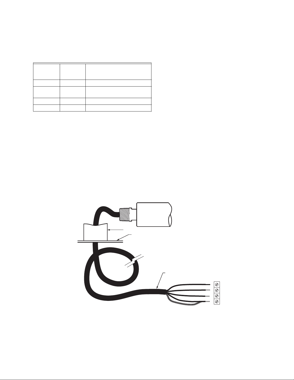
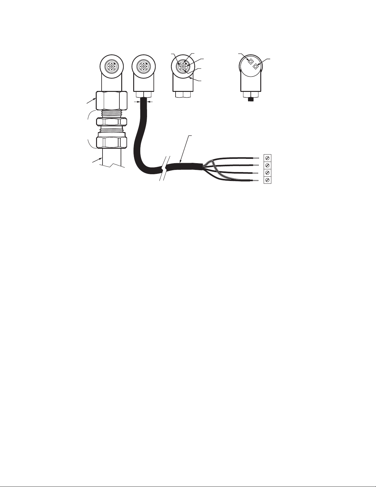
RED
BLACK
WHITE
GREEN
TERMINAL
VH SIG
VH SC
VH +V
VH GND
CONDUIT
ENCLOSURE
S702PF, S702HFPF OR S706PF
SHIELD
GRAY CABLE
WITH OVERALL SHIELD
STANDARD "PIGTAIL" LENGTH = 10 FEET (3 METERS)
M34285A
Viewing Head Connector and Wiring
Viewing heads are wired to the appropriate terminals located
on bottom of the 700ACSP, 700DCSP, P531 or P532 signal
processors. The terminals are listed functionally in Table 2.
Table 2. Terminal Descriptions.
700ACSP or
700DCSP
Ter minal
P531 or
P532
Terminal
VH SIG VH3 SIG Flame Signal from Viewing Head
VH SC VH3 SC Shutter Drive Signal to Viewing
Head
VH +V VH3 +V +24VDC Power to Viewing Head
VH GND VH3 GND GND Signal Ground
Connectors and cables are shown in Fig. 3, Fig. 4, and Fig. 5.
Fig. 3 shows the viewing head cable with the 1/2 in. NPT pipe
fitting and pigtail for use in a conduit. The gray cable is
labeled: LAPP USA UNITRONIC 190CY B (UL) TYPE CMG
105C 22AWG/4C SHIELDED E130334 – CSA CMG 105C or
AWM II A/B 300V LL74246. The standard pigtail length is 10
feet (3.0m). The S706PF-050 has a 50-ft (15 m) pigtail length.
This cable must be used with a conduit in hazardous
locations. It can also be ordered commercially as Olflex
602204S.
The recommended cable for hazardous locations, C330, is
shown in Fig. 4 with the right-angle connector and Fig. 5. It is
supplied as standard in a 15 ft. (4.6m) length with other
available lengths. This cable does not have to be used in a
conduit. It is labeled: C-330E193849 (UL) TYPE ITC 4/C 18
Description
AWG 90C 300V OR c(U L) CIC 90C 600 V FT4 SU NLIG HT
RESISTANT. C330 cable with or without the connector wired
at the factory can be purchased from Honeywell. Refer to
“Accessories” on page 10 for part numbers.
The customer may also supply his own cable; a replacement
mating viewing head connector should be ordered. Refer to
“Accessories” on page 10 for part numbers. The use of
shielded cable is recommended, either an overall shield or a
cable with a shield for the signal line. The shield should be
connected to GND at the processor end and to the ground
wire at the viewing head end. The cable diameter should not
exceed 0.307" in order for it to go through the hex bushing in
the connector. But note that wiring the cable to the connector
is not easy because of the limited space. Also, the LED
indicator assembly must be mounted inside the connector
and, preferably, soldered in place. Thus, it is recommended to
purchase a pre-wired cable and connector assembly from
Honeywell.
NOTE: FOR CLASS I, DIV 2 RATING, CABLING IN
HAZARDOUS LOCATIONS MUST COMPLY WITH
NEC ARTICLE 500 REQUIREMENTS AND
APPLICABLE GOVERNING CODES.
In the U.S., cables should have UL’s ITC rating; in Canada,
cables should have CSA’s CIC rating. The recommended
C330 cable has both ratings.
NOTE: To obtain a NEMA 4X seal between the connector
and the viewing head, tighten the metal
connector ring securely.
Fig. 3. Model 700 Viewing Head Cable With 1/2 in. NPT Fitting.
7 66-2069—01
HONEYWELL MODEL 700/800 SIGNAL PROCESSOR AND VIEWING HEAD
VH SC
700 LTA
T&B #5330
LIQUID
TIGHT
FITTING
FLEXIBLE LIQUID
TIGHT CONDUIT,
SUCH AS
ElectriFlex LT-516
5-16 (8)
MAX
Fig. 4. Model 700/800 Viewing Head Cable Connections.
Cable Preparation
NOTE: This section will typically be used for reference
Honeywell C330 cable is recommended for use with the
S70X/S80X viewing heads and signal processors. C330 cable
has a UL ITC rating and can be used in the US in hazardous
locations. Note the flame signal wire is shielded, and that the
shield must be terminated at both ends.
NOTES:
Connection of the Honeywell type C330 cable to the viewing
head plug is shown in Fig. 5. Cable preparation should be
done as follows:
• Remove the cable entry nut from the plug housing.
• Remove the retainer and rubber grommet.
• Unscrew the plug end from the connector body.
only. The S70X/S80X connector parts are very
small and delicate and difficult to assemble. It is
advisable to purchase pre-made cables from
Honeywell.
— The shield is used as the signal ground wire
which goes to terminal SIG GND on the signal
processor. The shield must be braided type for
this application in order to maintain an electrical
path. For this reason, a foil type shield should not
be used. The signal ground shield is also the selfchecking or shutter drive circuit return path. It is
recommended that the Honeywell C330 cable be
used for all S70X/S80X applications.
— Shield shrink tubing is required on the SIG GND
wire at both ends.
VH SIG
VIEWING HEAD
CONNECTOR
LOOKING AT PINS
C330 LIGHT BLUE CABLE
WITH SHIELDED WHITE CONDUCTOR
(RATED ITC BY UL & CIC BY CSA)
VH +V
VH GND/SHIELD
METAL
CONNECTOR
RING
GREEN
LED
SHIELD
WHITE
BLACK
RED
GREEN
VIEWING HEAD
CONNECTOR
LOOK ING AT BACK
TERMINAL
ORANGE
LED
VH SIG
VH SC
VH +V
VH GND
M34286
2. Slide the shield back until a bulge develops close to
where the wire exits the cable outer covering.
3. Carefully spread a few strands of the shield at the bulge
(making sure not to break any strands) to create an
opening and pull the wire out of shield through opening.
4. Carefully return shield to original shape and length by
pulling gently, then cover the shield with heat shrink
tubing to insulate it.
5. Slide the nut (with threads toward the cable end), the
retainer and the grommet onto the cable.
6. Slip the cable through the bottom opening of the
connector through the 90-degree bend and out the plug
end of the connector body.
7. Strip each wire 3/8” as shown in the assembly drawing.
8. Proceed to wire the connector as follows:
a. Connect the viewing head signal wire (the shielded
wire) WHT into the designated terminal by inserting
into opening and then tightening the retaining screw.
b. Connect the self-checking signal wire BLK to its
designated terminal.
c. Connect the signal ground shield from WHT wire
with shrink tubing to its designated terminal.
d. Connect the +24VDC power wire RED to its
designated terminal.
e. Connect the power ground wire GRN to the proper
terminal.
9. Carefully slide the wired plug end into the connector
body. Screw the plug onto the connector body until tight.
10. Reassemble the grommet, retainer and cable entry nut
and tighten to the connector body.
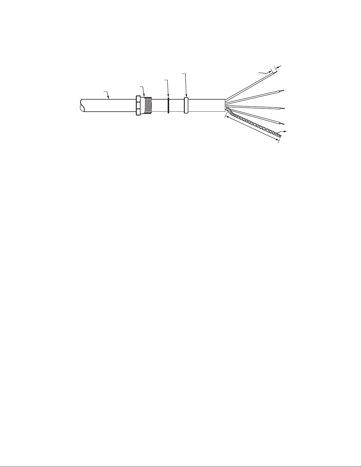
1. Strip 2 inches of the C330 cable outer cover from the
cable removing any cellophane wrap or filler material.
Strip the insulation from the shielded wire (if insulated
over shield) a full 2 inches to expose the shield.
66-2069—01 8
Cable at the signal processor end should be prepared in a
similar way to the plug end, particularly the shield from the
WHT wire. Follow the wiring connections as shown in Fig. 5,
making sure that the shield does not touch the other adjacent
terminals.
HONEYWELL MODEL 700/800 SIGNAL PROCESSOR AND VIEWING HEAD
3 CONDUCTORS PLUS 1 COAX
3 CONDUCTORS: 18 AWG
COLOR WHITE: 38 AWG BRAIDED SHIELD 90% COVERAGE
JACKET: TPE (TPAF) LIGHT BLUE
GROMMET
FLAT WASHER OR RETAINER
CABLE ENTRY NUT
CABLE
CABLE PREPARATION
STRIP 3/8" TYPICAL
1-19/64 (33)
NOTE: IMPORTANT INSULATE SHIELD WITH SHRINK TUBING LEAVING 3/8" STICKING OUT.
TYPICAL
Fig. 5. C330 Cable Preparation.
Protecting the Viewing Head Cable (Connector Series)
It is usually desirable to mechanically protect the cable going
to the viewing head. For the connector model viewing heads,
flexible conduit and adapters can be used for this purpose.
See Fig. 4. The 700LTA (liquid tight viewing head cable
adapter) is a custom part available from Honeywell; it screws
into the right-angle connector in place of the standard hex
bushing. The 700LTA is used with a Thomas and Betts #5330
liquid tight fitting which is designed to give a watertight seal for
flexible Liquatite
®
conduit, such as part number LT-516 by
Electri-Flex. The components have internal dimensions to
clear a 5/16 in. diameter cable. For each viewing head a
700LTA, a flexible conduit, and two T&B fittings will be needed.
Honeywell sells the 700LTA while the other parts can be
purchased commercially. The installer can fit the liquid tight
flexible conduit over the cable supplied with the viewing head
by first unscrewing the hex bushing from the connector and
removing it from the cable and then sliding the 700LTA, T&B
and flexible conduit assembly over the cable and screwing the
assembly into the right-angle connector. The flexible conduit is
terminated with the second T&B fitting which ends with a 3/8
in. NPT thread.
Note that when the wiring needs to meet Class I, Division 2
requirements for use in hazardous locations and when conduit
is used, the conduit must be sealed where the cable passes
from the hazardous location to the non-hazardous location in
order to keep potentially hazardous gases from being
conducted into the non-hazardous area.
Viewing Head Connector LED Indicators
The viewing head connector has orange and green LEDs
which can be viewed from the rear of the connector.
The green LED displays the pulses out of the viewing head
and the orange LED shows that the self-checking signal from
the signal processor is reaching the viewing head. If power is
on at the signal processor, the orange LED should flash at one
pulse per second, even if the viewing head is not plugged in.
This is helpful in troubleshooting.
With no flame signal present, the green LED will flash one
pulse per second in step with the self-checking signal. The
viewing head is sending back an ID pulse; this is part of the
self-checking system. When a flame is present, the green
LED will flash at a rate proportional to the flame signal, except
when the pulses are interrupted once per second for the selfcheck pulse arrival at the viewing head. The pulse rate of the
green LED flashes can be used for aiming the viewing head.
Viewing Head Mounting and Sighting
Mounting is 1/2-in. NPT (F) for all viewing head models with a
1/4-in. NPT (F) purge air connection. Before beginning the
actual installation, determine the best location for mounting
the viewing head based upon the following factors:
Viewing Head Mounting Block
The S70X viewing heads are held firmly in place in their
mounting blocks by two galvanized steel latches. The S80X
viewing head is secured in its mounting block by a friction
twist-lock. The mounting blocks are made from a hard Delrin
rated for continuous service to 180°F (82°C). An alternative
mounting block made from Ultem
and S80X viewing heads, rated for continuous service up to
320°F (160°C). Refer to the ACCESSORIES section for part
numbers.
Pressure
The S70X viewing head lens will withstand 50 psi (3.4 bar)
while the S80X lens will withstand 90 psi (6.2 bar), provided
the compression ring on the purge air adapter is tightened
properly. If the lens assembly is exposed to greater pressures
through the sight pipe, then an isolation unit must be used.
Honeywell isolation units with purge air entrance are available
SHIELD
M33282
®
1000 is available for S70X
9 66-2069—01

HONEYWELL MODEL 700/800 SIGNAL PROCESSOR AND VIEWING HEAD
as accessories; ISO-UNIT, ISO-UNITSS, ISO-UNITHPGT.
Each has a quartz window, two 1-in. NPTF connections and a
1/2-in. NPTF purge port.
Temperature
The case temperature of the viewing head housing must not
exceed 185°F (85°C) while the standard Delrin mounting
block must not exceed 180°F (82°C) continuous service. Care
should be taken to ensure the case housing and mounting
block temperatures do not exceed these values.
Purge air will help reduce conducted heat through the sight
pipe and flange. A heat insulating Ultem replacement viewing
head mounting block is available for both the S70X/S80X
models (part numbers 700UA and 800UA) with a continuous
service rating of 320°F (160°C) as well a 1/2-in. NPTM Ultem
nipple (part number R-518-13) or an Ultem locking coupler
adapter (R-518-PT13 or R-518-PT13L) to reduce the
conducted heat, but direct radiation can cause the housing
case temperature to exceed limits. If the ambient heat (direct
radiation) is excessive, then an air cooling canister with vortex
cooler should be considered or alternately a fiber optic
extension. The extension uses a fiber optic cable assembly
between the sight pipe and the viewing head, allowing the
viewing head to be placed further away from the heat source.
Refer to the Fiber Optic Manual 69-2683 or contact your
distributor or the factory for assistance with fiber optic
selection and pricing.
as possible so as to sight along the flame rather than across
the flame. Doing so will ensure continuous flame detection
under changing load conditions. See Fig. 14, 15 and 16.
Utilizing a sighting or the sight pipe aimed at the root of the
flame (where the turbulent combustion air mixes with the
flame) is a good starting point for optimizing the sighting.
Where practical, using a swivel mount to "zero-in" on the
highest signal will assure maximum performance. The
optimum scanner location is parallel to the burner center line.
The use of a swivel mount allows for line of sight adjustment,
where practical to use.
Examples of viewing head installation with and without a
swivel mount are shown in Fig. 12 and Fig. 13. If using a sight
pipe, its diameter should be large enough to allow a
reasonable field of view, and to allow for adjustment of the
swivel mount angle.
In some instances, it may be beneficial to use two sets of
setpoints for Flame On, Flame Off and gain. The two-channel
capability (primary and alternate viewing head settings) is
ONLY possible when using the P531 or P532 signal
processors; it is not possible when using the 700ACSP or
700DCSP signal processors. The switch-over from Channel A
to Channel B can be implemented from the burner control
system. Refer to the P531/P532 user manual, 66-2068, for
further information regarding switch-over and the use of
Channels A and B with independent settings.
Purge Air
Use a flexible air supply line, to allow for repositioning of the
viewing head and sight pipe until a final and permanent
position has been decided. A continuous flow of air must be
maintained in order to reduce the conducted heat and to keep
the sight pipe and viewing head lens free of dirt and debris. Air
required is about 5 SCFM (0.13 Nm3 /min) delivered at 1 in.
(25mm) above the maximum pressure as measured at the "Y"
or "T" section of the purge air connection for each viewing
head. The air supply must be clean, free of oils and water, and
preferably cool. In order to electrically isolate the viewing
head, the purge air line should be installed using an insulating
material, such as a rubber hose, in between the purge air line
and the viewing head.
Vibration
Do not install the viewing head where it could be subject to
high vibration. Provide an anti-vibration mount if excessive
vibrations are present.
Clearance
Make sure there will be sufficient room to remove the viewing
head housing for servicing.
Viewing Head Mounting
Honeywell offers a range of swivel mounts, both pipe thread or
flange mounting for use with sight pipes or direct windbox
mounting. See “Accessories” on page 10 or the Honeywell
website for further details.
Viewing Head Sighting
The sighting of the viewing head should be parallel to the
center line of the burner in the direction of the flame. If used,
the sight pipe should be mounted as close to the center line
ACCESSORIES
Orifice disks (kit M-702-6) - Used to reduce the signal
brightness in cases where the signal brightness is too strong.
Located immediately in front of the lens, it will reduce the
amount of signal to the sensor. Bag assembly contains orifice
disks and retaining rings. Orifice disks come with 3/8, 1/4,
3/16 and 1/8 inch diameter holes. Contact the factory for
guidance in using orifice disks.
Insulating nipple (R-518-13) - 1/2-in. NPTM Ultem heat and
electrical insulating nipple typically used in conjunction with a
swivel mount and union.
VH insulating mounting block (700UA, 800UA) - 1/2 in.
NPTF Ultem heat and electrical insulating mounting block,
used in place of the supplied Delrin mounting block. 1/4 in.
NPTF purge air connection. Typically used in conjunction with
a swivel mount. Rated for continuous service up to 320°F
(160°C).
Swivel mounts, small (700-1, 700-2, 700-3) - All have 1/2 in.
NPTM viewing head connections on one end with varying
process connections including 1 in. NPTF, 1/2 in. NPTF and
1/2 in. flanged.
Swivel mounts, large (M-701-1, M-701-2, M-701-2-FLG, M701-2-SS, M-701-3, M-701-3P, M-701-4) - All have 1 in NPTF
viewing head connections, one end with varying process
connections including 2 in. pipe slip on, 2 in. NPTF, 2 in.
flanged, 2 in. NPTF in stainless steel construction, 4.5 in.
flanged with 3 bolts, 3 in. NPTF and 2-bolt flanged.
Appropriate fittings must be used to adapt the 1/2 in. NPTF
viewing head process connections.
66-2069—01 10

HONEYWELL MODEL 700/800 SIGNAL PROCESSOR AND VIEWING HEAD
Insulating locking coupler adapters (R-518-PT13, R-518PT13L) - 1/2 in. NPTM Ultem adapters insulate the viewing
head electrically and thermally and are used with the R-518CL13-HTG locking couplers. The R-518-PT13L has a quartz
lens.
Locking coupler (R-518-CL13-HTG) - Used with the R-518PT13 and R-518-PT13L insulating locking coupler adapters.
Process connection end is 1/2 in. NPTF.
Connector (ASY784) - Replacement quick disconnect
connector for all S70X/S80X models.
Connector + Cable (ASY782) - Replacement pre-assembled
15-foot (4.7m), 4-conductor cable (C330) with quick
disconnect (ASY784) for all S70X/S80X non-pipe fitting
models. There are also five more pre-assembled cable and
connector assemblies available; ASY782-030 (30ft/9m),
ASY782-050 (50ft/15m), ASY782-100 (100ft/30m), ASY782200 (200ft/61m) and ASY782-250 (250ft/76m).
Cable (C330) - 4 conductor cable with braided shield. Sold
per foot.
Isolation Units (ISO-UNIT, ISO-UNITSS, ISO-UNITHPGT) -
All have 1 in. NPTF connections with 1/2 in. NPTF purge ports
and quartz window. Painted aluminum or stainless steel
construction. The HPGT version has a 1/2 in. thick quartz
window for higher pressures. Appropriate fittings must be
used to adapt the 1/2 in. NPTF viewing head process
connections.
Liquid tight cable adapter (700LTA) - S70X/S80X viewing
head cable adapter with 3/8 in. NPTF conduit connection.
Air cooling canister (700ACC, 800ACC) - Has an air inlet
port on side. Used with vortex coolers. S80X models can be
used with the 700ACC if the 800ACC-RING adapter is used.
Vortex coolers (M3204, M3208, M3210, M4025) - Used with
air cooling canister. Contact your distributor or the factory for
selection assistance.
Cable restraints (800CR, 700CRLT) - Liquid tight S80X and
S70X cable restraint versions. The 800CR includes the
700CRLT and the 800ACC-RING adapter.
S80X adapter ring (800ACC-RING) - Adapter ring to fit S80X
viewing heads to 700ACC cooling jacket and 700CRLT liquid
tight cable restraint.
Right angle adapter (700RAA) - S70X/S80X viewing head
right angle adapter. 1/2 in. NPTF to 1/2 in. NPTM connections.
Mounting blocks (700DA, 700DA-1, 800DA) - Delrin
replacement adapter/mounting blocks for S70X and S80X
viewing heads. All have 1/4 in. NPTF purge air connections.
Rated for continuous service up to 180F (82C). The 700DA
and 800DA have 1/2 in. NPTF process connections while the
700DA-1 has a 1 in. NPTF process connection. For more 1 in.
NPT accessories that can be used with the 700DA-1, refer to
the S55XB/BE manual, 66-2064.
USB to RS422/RS485 Converter (COMMOD) - Protocol
converter for use with external communication with a remote
computer.
Fiber Optic System Compatibility - The S70X and S80X
viewing heads are compatible with the Honeywell FASA fiber
optic extension products. The S700FOAD and S800FOAD
adapters are applicable, depending on the application.
Contact your distributor or the factory for assistance with fiber
optic selection and pricing.
OPERATION
IR Detector
The S702 and S802 viewing head models use a Germanium
photodiode, which responds to IR radiation/flicker in the flame.
Flame flicker is caused by the combustion, or forced air
injected in to the flame. Combustion air can be mixed with the
fuel (pulverized coal) or can be introduced separately. In either
case, forced air is introduced in such a way as to aid the
combustion process. This air is usually made turbulent by
causing it to swirl with spin vanes located in the burner throat.
Flame flicker is created when turbulent air mixes with the
flame. It is composed of random frequencies and the amount
of high frequency flicker is dependent on the fuel and the
burner.
The S702, S702PF and S802 viewing head models respond
to flicker frequencies above 33Hz while the S702HF,
S702HFPF and S802HF viewing heads respond to flicker
frequencies above 155Hz. All flicker frequencies below the
filters are ignored, so it is important to sight the viewing head
on the highly turbulent portion of the flame that contains the
higher frequencies. The location of the higher frequencies can
be predicted by examining the burner with regard to where the
turbulent air enters the flame. The optimum scanner location
is parallel to the burner center line (Fig. 14). The use of a
swivel mount is encouraged to allow for line of sight.
Filter Selection for IR Viewing Head
If a good count ratio between BNR-ON and BNR-OFF cannot
be obtained when using an IR viewing head—particularly
when monitoring oil flames—an IR viewing head with the High
Frequency (HF) filter option is recommended. The standard IR
viewing head responds to flicker frequencies above 33 Hz;
with the HF option, the IR viewing head responds to flicker
frequencies above155 Hz.
UV Detector
The S706, S706PF and S806 viewing head models use the
UVTron tube, with a spectral response of 185-260nm and
peak response of 210nm to ultraviolet radiation. The output of
the detector is a pulse stream of randomly spaced pulses
whose average rate is proportional to the UV radiation present
in the flame. The UV radiation is a direct result of the
combustion process as oxygen combines with hydrocarbons
in the fuel in the blue part of the flame. The yellow part of
flames, and the background radiation from hot refractory, do
not emit UV radiation.
The spectral range of the UV tube makes it ideal for
discriminating between flame and glowing refractory. As with
any UV radiation, it can be absorbed or masked by unburned
fuel, smoke, oil mist, dirt dust and other impurities in the fuel.
Care should be taken to select the proper viewing head for the
fuel used. Additionally, the contaminants that mask UV can be
diluted by providing a strong flow of air through the sight pipe
to clear a viewing path through the attenuating material. See
“Purge Air” on page 10.
11 66-2069—01

HONEYWELL MODEL 700/800 SIGNAL PROCESSOR AND VIEWING HEAD
It may also be desirable to sight the detector at an area
containing fewer masking agents such as near the burner
nozzle or near the entrance of the combustion air. Increasing
the viewing area of the detector by shortening the sight pipe or
by increasing the diameter of the sight pipe can also reduce
the attenuating effects of the masking agents.
In general, the UV viewing heads will work well on natural gas
and light oil flames. The sighting for both oil and gas flames
should be parallel to the axis of the burner and aimed at the
root of the flame, as with the IR detector. (See previous
section, "IR Detector.") The highest UV intensity occurs near
the root of the flame (Fig. 15). In addition, the zone of higher
UV intensity does not overlap the same zones of adjacent or
opposing burner so that, with proper sighting, discrimination
can be achieved.
With low NOx gas burners, the UV radiation is usually much
less in intensity and spread out. Relatively high readings can
be obtained from all over the furnace when many burners are
in service. This is particularly true when flue gas recirculation
is used. There will however, be a relatively stronger signal
near the "root" of the flame and the more intense spot should
be located during the aiming or sighting process. This "root" or
intense spot may be further out than with the standard gas
burner so it is imperative that a swivel mount be used when
making sighting adjustments.
Another factor that needs to be considered when aiming the
viewing head is the load condition of the boiler. The flames
from a burner can be radically different at different loads. This
is one of the reasons for choosing an optimum sighting initially
that will minimize signal swing due to changing loads.
Self-Checking
There is a small processor in both the IR and UV viewing
heads, so it is possible that this processor could fail and
produce erroneous viewing-head pulses. The self-check
circuitry guards against this. There are several tasks that
require intelligent interaction between the viewing heads and
the signal processor. If all of these interactions do not occur
properly, the viewing head will not send pulses back to the
signal processor and the flame relay will open.
Verifying the validity of the gain code received is one of the
tasks performed by the processor in the IR and in the UV
viewing heads. The self-check pulse from the signal
processors is a 100ms-wide, 20V to 24V pulse with two
“notches” or breaks in it. The position of each of the two
notches communicates a gain code of one to nine plus parity
to the viewing head. The viewing head sends back an ID
pulse in the first half of the 100ms self- check time. A viewing
head expects to receive data with a certain parity. If a viewing
head does not receive its correct parity plus the gain code
once per second, it produces no output pulses.
There is also intelligent interaction between the older S706
viewing heads, which did not have the gain-change feature
from the signal processor. The processor in the S706 viewing
head monitors the 100ms width of the self-check pulse
coming from the signal processor. If the pulse is not the
correct width the viewing head produces no output pulses.
Also, if the signal processor receives any pulses back from the
viewing head during the last half of the100ms self-check time,
it assumes that a processor failure has occurred in the viewing
head, opens both relays, and displays “LO” (lockout).
Adjustment of VH Sighting and Gain
NOTE: Adjustment to the viewing head parameters
cannot be made unless the viewing head is
connected and communicating with the signal
processor.
The viewing head should be properly sighted before the
setpoints are adjusted. Adjustment can be made easier by a
1/2 in. swivel joint, which Honeywell can supply if one is not
available (refer to “Accessories” on page 10).
While the burner is firing, vary the viewing angle while
observing the green LED on the connector at the rear of the
viewing head. Adjust the viewing angle for the maximum pulse
rate, then lock the swivel joint to preserve this mechanical
setting. If the green LED pulse rate is very high or very low,
see the two paragraphs below. The locked mechanical setting
should still be correct when Model 700 viewing heads are
interchanged, because inside each Model 700 viewing head
the optical axis is aligned with the mechanical axis within ±1/4
degree. Also, the reading shouldn’t change when a viewing
head is rotated in the mount.
For the above sighting adjustments to work properly, the
flashing rate of the green LED in the connector at the rear of
the viewing head must be reasonable. On the -PF (pipe fitting)
version, there are no LEDs. The installer must observe the
flame signal on the signal processor instead.
A count rate of 16 to 20 is recommended for proper operation.
If the displayed count is above 25, the pulses begin to blur
together, making changes in the pulse rate difficult to observe.
If the count is higher (29 or 30), then the viewing head is
saturated. Saturation indicates that the count could be even
higher, possibly 50 or more, but it is internally clamped. With
count rates at or close to saturation, the installer will not be
able to adjust the viewing head in the swivel mount to
maximize the count rate properly. It should be possible to
sufficiently decrease the count rate to a usable level by
decreasing the gain. See “Manual Setup of Setpoints” on
page 13 of this manual. If the gain is set to 1 and the count is
still 25 or higher, orificing is likely required. See the section on
orificing below.
If the displayed count is less than 8 or 10, it will be difficult to
maximize the count by adjusting the viewing head aim, since
the pulses occur too infrequently. In such a case the gain
should be increased. If the gain is set to a maximum and the
count rate persists below 8 or 10, the system can still be made
to work reliably as long as the count rate drops significantly
when the flame is removed. However, the setup should be
reviewed for proper viewing head aim and sight path to ensure
it is optimized.
Orificing
Orifice disks have been used in applications with older viewing
heads that did not have adjustable gain in order to reduce the
extreme brightness of certain burner flames. The orifice disk
kit is part number M-702-6. Orifice disks come with 3/8, 1/4, 3/
16 and 1/8 inch diameter holes. Contact the factory for
guidance is using orifice disks. The disks are installed with
retaining rings in the flange at the edge of the 1/2 inch NPT
female pipe thread for the process connection. An internal
type retaining ring is first installed by positioning a ring in the
machined groove inside the flange opening from the housing
66-2069—01 12
 Loading...