

7800 SERIES
S7800A1142 Keyboard Display Module
PRODUCT DATA
The S7800A1142 KDM offers the following technical
advancements to the 7800 SERIES devices:
• Compatible with installed Honeywell 7800 SERIES
systems.
• When used with the new 7800 SERIES with Valve Proving
Feature, the KDM allows for programming the Valve
Proving Control feature and timing (Pass Code protected
feature).
• Allows for naming the S7830 Expanded Annunciator
terminals to match your system drawings. (Displayed
message only.)(Pass Code protected feature.)
• A three screen two-row by twenty-column readout set of
“Call Service” (Business Card) alpha/numeric directions
can be displayed instead of the standard lockout display
message. (Pass Code protected feature). This “business
card” can be cloned to other displays to save setup time.
• Enable ModBus Communication feature.
APPLICATION
The S7800A1142 Keyboard Display Module (KDM) provides
current system status along with first-out annunciation and
system diagnosis using a two-row by twenty-column readout.
The KDM provides local or remote annunciation of operation
and fault information, remote reset, report generation, burner
control data and diagnostic information. The KDM is part of
the 7800 SERIES of microprocessor-based burner controls for
gas, oil, coal or combination fuel single burner applications.
The 7800 SERIES is programmed to provide a level of safety,
functional capabilities and features beyond the capacity of
conventional controls.
The S7800A1142 is required to program the Valve Proving
feature of select 7800 Series devices.
Contents
Application ........................................................................ 1
Features ........................................................................... 2
Specifications ................................................................... 2
Ordering Information ........................................................ 2
Installation ........................................................................ 3
Wiring ............................................................................... 4
Troubleshooting ................................................................ 12
Hold and Fault Message Summary .................................. 16
Appendix A:Display Setup ............................................... 25
Display Setup—CLONE ............................... 25
The Business Card (Call Service) and Expanded Annunciator
can be made up using:
• Capital letters (A through Z).
• Lower case letters (a through z).
• Numbers (1 through 0).
• Symbols (!, @, #, $,%, etc.).
• Spanish symbols.
Programming can be done with the S7800 KDM mounted on a
7800 SERIES Relay Module or with a 13 Vdc power source
connected to the KDM through the 203541 5-wire connector.
Since your Business Card (Call Service) S7800A1142 will be
left at the job site, programming your personal three-number
password and personal lockout message can be set up ahead
of time without being connected to a 7800 SERIES device. A
clone function allows you to make multiple Business Cards
from the original display.
Contents
Appendix A:Display Setup—Clear All .............................. 27
Display Setup—CEA Assign ......................... 29
Display Setup—CS ON/OFF ........................ 31
Display Setup—CS EDIT .............................. 32
Appendix B:Valve Proving System ................................... 34
Setup of Valve Proving Function .................. 34
Appendix C: Setup of Post Purge ..................................... 36
Appendix D: Expanded Annunciator Tables ..................... 37
Appendix E: ModBus Function ......................................... 38
65-0288-1
7800 SERIES S7800A1142 KEYBOARD DISPLAY MODULE
WARNING
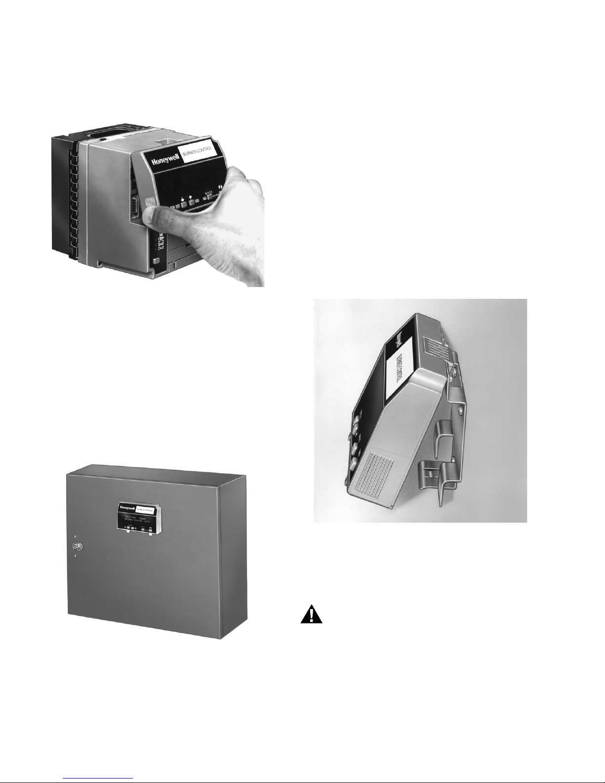
Mounting KDM on 7800 SERIES Relay Module.
1. Align the two interlocking ears of the KDM with the two
mating slots on the 7800 SERIES Relay Module. See
Fig. 2.
Fig. 2. Keyboard Display Module mounting.
2. Insert the two interlocking ears into the two mating slots
and, with a hinge action, push on the lower corners of
the KDM to secure it to the 7800 SERIES Relay Module.
3. Make sure the KDM is firmly in place.
4. Drill the pilot holes for the mounting screws.
5. Cut holes in the door panel for the interlocking ears and
the two plug-in connectors.
6. Mount the KDM, securing it with the two screws provided
in the KDM bag assembly.
Remote Display Mounting Bracket
Use the 203765 Remote Display Mounting Bracket when
mounting the KDM on a wall or remote location:
1. Use the 203765 Remote Display Mounting Bracket as a
template to mark the four screw locations.
2. Drill the pilot holes for the four mounting screws.
3. Mount the 203765 Remote Display Mounting Bracket by
securing the four no. 6 screws (M3.5 x 0.6). See Fig. 4.
4. Mount the KDM by aligning the two interlocking ears with
the two mating slots on the remote mounting bracket.
5. Insert the two interlocking ears into the two mating slots.
6. Push on the lower corners of the KDM to secure it to the
remote mounting bracket.
7. Make sure the KDM is firmly in place.
Remote Mounting KDM
The KDM can be mounted either on the face of a panel door or
on other remote locations. See Fig. 3. When mounting the
KDM on the face of a door panel, closely follow these
instructions:
Door Panel Mounting
Fig. 3. Panel mounting of a Keyboard Display Module.
1. Select the location on the door panel for flush mounting.
2. Pay attention to the insertion dimensions of the two KDM
screws, two interlocking ears, and the two plug-in connections to allow for sufficient clearance.
3.
Use the KDM or Data ControlBus Module™ as a template
(Fig. 19) and mark the two screw locations, interlocking
ear locations and the two plug-in connector locations.
Fig. 4. Remote mounting of a Keyboard Display Module
using a 203765 Remote Display Mounting Bracket.
WIRING
Electrical Shock Hazard.
Can cause severe injury or death.
To prevent electrical shock and equipment damage,
disconnect the power supply from the main disconnect
before beginning installation. More than one disconnect
can be involved.
1. Refer to Fig. 5, 6, and 7 for proper wiring.
2. Make sure all wiring complies with all applicable
electrical codes, ordinances and regulations.
3. For recommended wire size and type, see Table 1.
65-0288-1 4
7800 SERIES S7800A1142 KEYBOARD DISPLAY MODULE
M24165
PILOT IGN 00:05
Fault History
M22872
PILOT IGN 00:10 H1
Fault Cycle 174
BURNER CONTROL
BURNER CONTROL
EDIT:
BACK
- ENTER -
_
+
EDIT:
BACK
- ENTER -
_
+
Fig. 9. S7800 Keyboard Display Module.
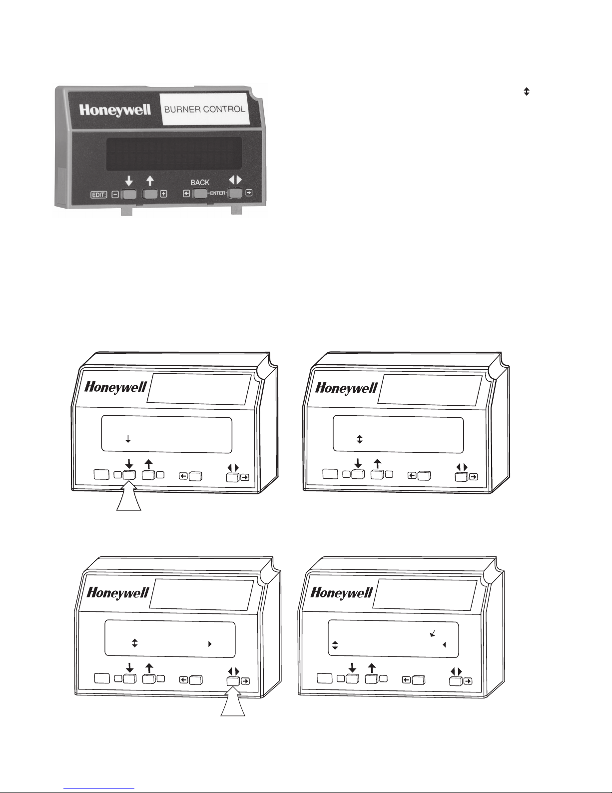
Keyboard Functions
The keyboard contains four push-buttons with separate
functions (SCROLL-down, SCROLL-up, MODE, and
CHANGE-LEVEL). The MODE and CHANGE-LEVEL, when
pressed together, provide a SAVE function. When in the Setup
Screen—Mode and Change Level serves as Menu or Enter.
1. Down-up arrow push-buttons. See Fig. 10. The down-up
arrow push-buttons are used to scroll through the
selectable messages. The double-headed arrow ( ),
which is located in the lower left position of the second
line of the display, represents the down-up push-buttons.
The down-up push-buttons can be pressed to display the
selectable messages one at a time or held down to scroll
through the selectable messages at the rate of two per
second. When the last item of the selectable message is
viewed, the display wraps around and displays the first
selectable message again.
2. The
push-button, see Fig. 11. The
push-button
is used to change between the first hierarchy of
selectable messages to a subset of selectable
messages. The
push-button can also be used to
change from a subset message to a first level selectable
message. The symbol located on the second line in the
lower right corner of the display, represents a subset of
selectable messages.
3. BACK push-button, see Fig. 12. Use the BACK
push-button to instantaneously switch the display from a
second-line selectable message to a second-line
preempted message. The sixty second time-out function
can also be used for this task. The BACK push-button
only works if there is a second-line preempted message
or a lockout message.
BURNER CONTROL
RUN
Total Cycles 333
_
EDIT:
BURNER CONTROL
RUN
Total Hours 1332
+
BACK
- ENTER -
EDIT:
_
+
BACK
- ENTER -
M22871
Fig. 10. Push-button function.
65-0288-1 8
Fig. 11.
push-button function.
7800 SERIES S7800A1142 KEYBOARD DISPLAY MODULE
STANDBY
Total Cycles nnn
M24043
BACK
ENTER
Edit:
- +
– Save Display
. . . Saving . . .
BURNER CONTROL
LOCKOUT 17 DI
Main Valve T9 = 0
_
EDIT:
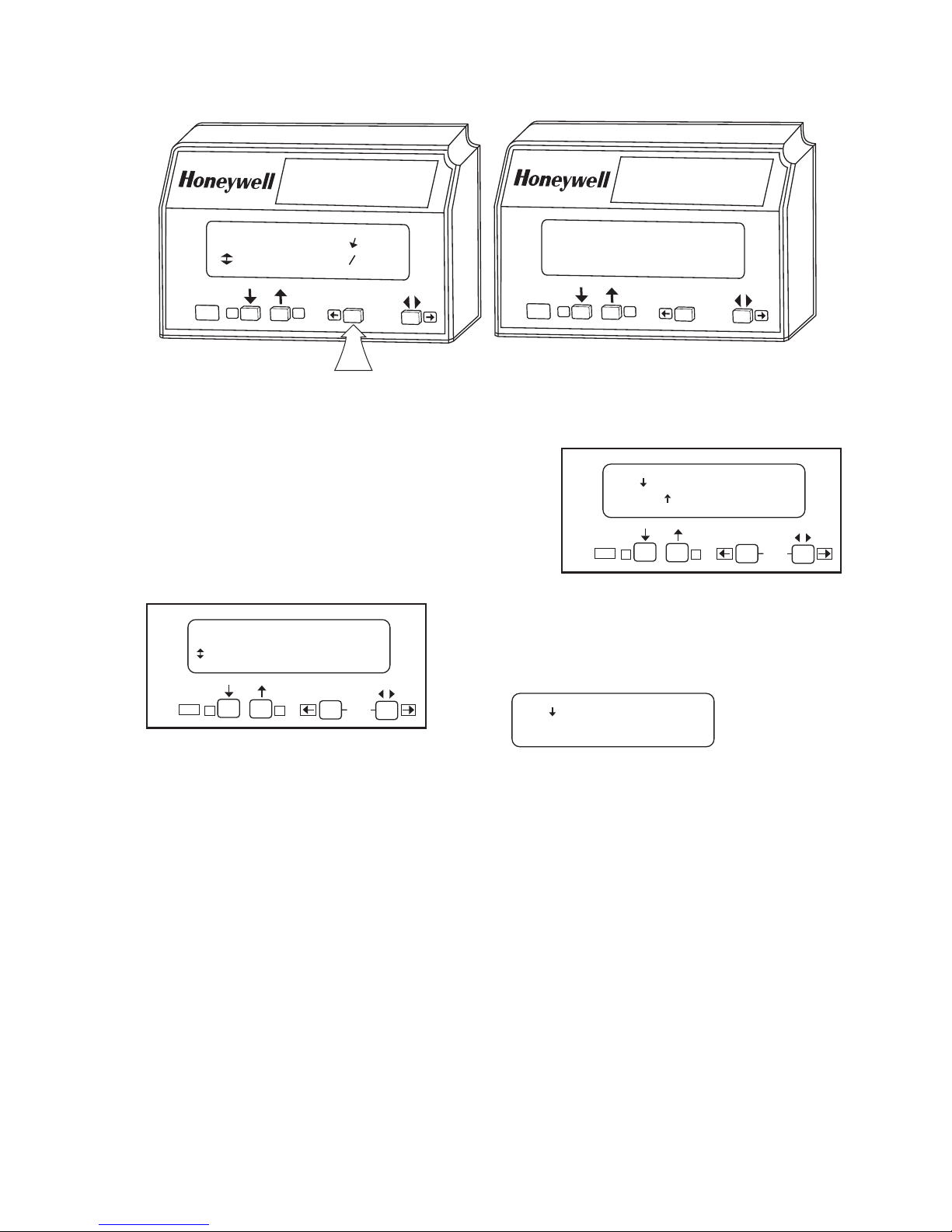
4. SAVE function, see Fig. 13, 14, and 15.
a. Enables users to identify the selectable 2nd line
message they want to view upon power restoration.
(See “Total Cycles” instead of “Flame Signal” for
example.) The second line selectable message is
restored to the most recently saved selection when
power returns.
b. Press the down-up arrows until the desired second
line is displayed. Press the ENTER function. (See
Fig. 13.)
BACK
+
- ENTER -
Fig. 12. BACK push-button function.
BURNER CONTROL
LOCKOUT 17
*Main Flame Fail*
_
E
DI
T
:
+
Edit:
-+
Fig. 14. Save Display/Exit screen
BACK
- ENTER -
M22873
– Save Display
– Exit
BACK
ENTER
M22874
Fig. 13. SAVE function.
c. The following Display will appear:
d. Press the to save the desired second line. Press-
ing the will EXIT without changing the second line.
Fig. 15. Save Display...Saving screen.
The second line of the display is now changed to the new
selected message.
9 65-0288-1

7800 SERIES S7800A1142 KEYBOARD DISPLAY MODULE
Table 3. Selectable Messages .
Selectable
Message/Display
Flame Signal
Total Cycles
Flame signal strength. 0 - 5.0 Vdc Flame Amp (+ and
Total number of equipment
Description
operating cycles.
Total Hours
Total number of equipment
operating hours.
Fault History >
(Six most recent faults)
Fault Cycle Ë
First level prompt for history
information. Has subset level.
Cycle when fault occurred. 0 - 99,999 cycles (250,000;
H1
Fault Hours Ë
Run hour when fault occurred. 0 - 99,999
H1
Fault Code Ë
H1
*Fault Message* Ë
Number that identifies the
reason for lockout.
Indicates cause of lockout. — —
H1
Sequence Message Ë
H1
Indicates where in the
sequence the lockout
occurred.
(Second Line Message) Ë
H1
Second line message explains
any further information that is
available from the 7800
SERIES or may be blank if
there is not a preemptive
second-line. H2…H6 etc.
Diagnostic Information >
First level prompt for
diagnostic information. Has
subset level.
Device
Device Suffix
Run/Test Sw.
OperControl T6
Interlock T7
Pilot Valve
Main Valve
Ignition
LowFire Sw
HighFireSw
Device type number. RM78XXX, R7140, or
Device suffix number. nnnn —
Position of Run/Test Switch. RUN or TEST Indicates if 7800 SERIES is in
Operating Control Input. = 1 or 0 Indicates if input is on or off,
Running/Lockout Interlock. = 1 or 0 Indicates if input is on (1) or off
T8 Pilot Valve. = 1 or 0 Indicates if output terminal is
T9 Main Fuel Valve. = 1 or 0 Indicates if output terminal is
T10 Ignition. = 1 or 0 Indicates if output terminal is
T18 Low Fire Switch. = 1 or 0 Indicates if input is on or off,
T19 High Fire Switch. = 1 or 0 Indicates if input is on or off,
PreIgn ILK T20 or T17b Pre-Ignition
Interlock
Possible States/ Range
(Terminals)
Comments
Flame relay pull-in and drop-
- (Com))
0 - 99,999
(250,000; 999,999c) cycles
0 - 99,999
(250,000; 999,999
c
) hours
out value 1.25 Vdc.
Cycle will be updated each
a
time main valve is energized.
Hour will be updated each time
a
main valve output is energized
for 60 minutes.
— —
—
999,999
c
) cycles
—
(250,000; 999,999
c
) hours
a
0 - 999 —
— —
— —
— —
—
EC78XXX
RUN or TEST mode.
energized or de-energized.
(0), energized or de-energized.
on or off, energized or
de-energized.
on or off, energized or
de-energized.
on or off, energized or deenergized.
energized or de-energized.
energized or de-energized.
= 1 or 0 Indicates if input is on or off,
energized or de-energized.
65-0288-1 10

Selectable
Message/Display
Val v/Start
Jumper 1
Jumper 2
Jumper 3
Amp Type
Flame Response
Purge Time
7800 SERIES S7800A1142 KEYBOARD DISPLAY MODULE
Table 3. Selectable Messages (Continued).
Possible States/ Range
Description
T21 Interrupted/Intermittent
Pilot Valve, First Stage Oil
= 1 or 0 Indicates if output is on or off,
(Terminals)
Comments
energized or de-energized.
Valve or Start Input.
Pilot Flame Establishing
Period (PFEP).
INTACT/CLIPPED Display shows state of PFEP
jumper. If jumper is intact,
7800 SERIES was 10 second
PFEP. If jumper is clipped,
7800 SERIES has 4 second
PFEP.
First Safety Time (for RM/
EC7850).
INTACT/CLIPPED Display shows state of First
Safety Time (EC7850) jumper.
If jumper is intact, EC7850 has
5 second First Safety Time. If
jumper is clipped, the EC7850
has 3 second First Safety
Time.
Pilot Valve. INTACT/CLIPPED Display shows state of Pilot
Valve (terminal no. 21). If
jumper is intact, RM7800G has
Intermittent Pilot Valve. If
jumper is clipped, RM7800G
has 15 or 30 second
Interrupted Pilot Valve.
Main Trial Time (for RM/
EC7850).
INTACT/CLIPPED Display shows state of Main
Trial Time (EC7850)Valve
(terminal no. 21). If jumper is
intact, EC7850 has 5 second
Main Trial Time. If jumper is
clipped, EC7850 has 3 second
Main Trial Time.
Start-up Airflow Switch (AFS)
check.
INTACT Disabled/CLIPPED
Enabled
Display shows state of Start-up
AFS check jumper. If jumper is
clipped, RM7800 AFS check is
enabled and if jumper is intact,
AFS check is disabled.
Defines type of amplifier
installed.
STANDARD/AMP-CHECK/
SHUTTER
Display shows type of flame
detection system installed (i.e.,
as STANDARD, AMP-CHECK/
AMPLI-CHECK™ and
SHUTTER/ Dynamic SelfChecking).
Amplifier Flame Failure
Response Time (FFRT) in
0.8 second, 1 second, 2
seconds, or 3 seconds
—
seconds.
Timing value of purge card. mm:ss Two seconds to 30 minutes.
a
European Approved Controls.
b
Pre-Ignition Interlock Terminal 17 or 20 is model dependent.
c
Valve Proving Device or RM7897.
d
The display values are as follows:
n represents a numbered value.
T represents the terminal number.
x represents the suffix letter of the Relay Module.
Expanded Annunciator Messages (Table 4)
The Expanded Annunciator (EA) may or may not be connected
because it is an optional device. If the EA is not connected, a
display message of “(EA not connected)” is shown. If the EA is
connected, display messages are shown; see Table 4 (Note
that 1 means ON and 0 means OFF). When accessing
Expanded Annunciator messages, follow the same operations
as used with the Selectable messages.
11 65-0288-1
 Loading...