

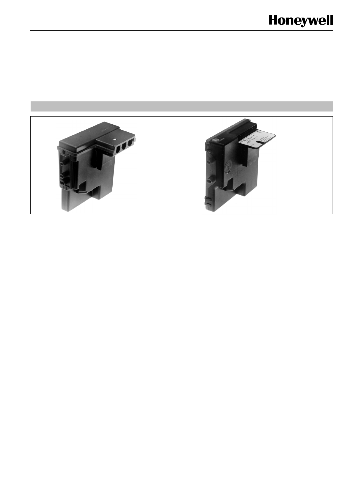
S4565/S4575/S4585 SERIES
IGNITION CONTROLS FOR COMBINED VALVE AND IGNITION SYSTEM
INSTRUCTION SHEET
”Old”-- style
APPLICATION
The Combined Valve and Ignition system (CVI) has specially
been developed for application in gas fired appliances with
either intermittent pilot or direct burner ignition.
For this system, the VK41../VK81.. series gas controls have
been designed to have the S4565/S4575/S4585 series
ignition controls attached directly onto the valve.
The combined system then provides programmed safe light
up, flame supervision and regulation of gas flow to the main
burner and/or pilot burner of the appliance.
DESCRIPTION
The S4565/S4575 ignition controls provide automatic ignition
for direct gas burner applications and for intermittent pilot gas
burner applications with safety timer.
The S4565/S4575 ignition controls are not intended for direct
exposure to flame envelope.
The S4585 ignition controls provide automatic ignition for
intermittent pilot gas burner applications without safety timer.
The S4565/S4575/S4585 ignition controls are designed to
meet the european standards:
EN 298: Automatic gas burner control systems.
EN 60730--1: Automatic electrical controls for house hold
and similar use.
The S4565/S4575/S4585 ignition controls can be used in
appliances according European standard for household
electrical requirements EN 60335 series.
The S4565/S4575 ignition controls are approved on the North
American standard ANS Z21.20 Automatic Ignition Systems.
NOTE: S4565SD is not an ignition control but an ignition
circuit and rectifier only
”New”-- style
Contents
Page
Dimensional drawing 2................................
Features 3...........................................
S4565A,B,P,Q 3.......................................
S4565C,D,R,T 4.......................................
S4565AD,BD,CD,DD,PD,QD,RD,TD “1000” series 7......
S4565AD,BD,CD,DD,PD,QD,RD,SD,TD “2000” series 13..
S4565AF,BF,CF,DF,EF,PF,QF, RF, TF 18..................
S4575A,B,C,D,P,Q,R,T 23..............................
S4585D 26...........................................
General considerations 27.............................
Electrical connections 28..............................
Subject to change without notice. Printed in the Netherlands.
EN1R--9161 0006R10--NE
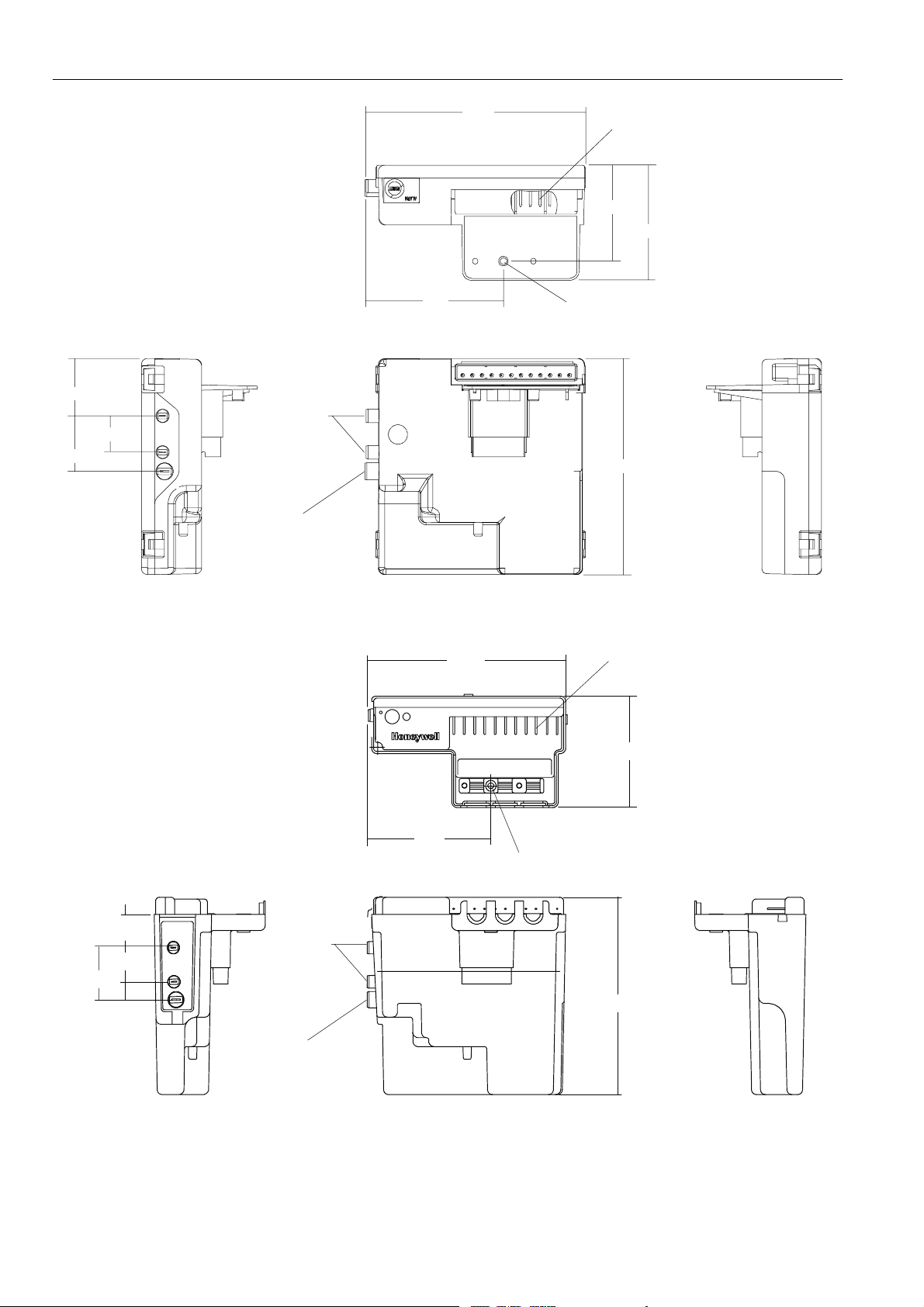
115
f
Connector pins suitable for
Molex 3001 female connectors
50
60
30
29
19
72
Mounting hole Ø 3.2
Ignition
113
Flame detection
Note: specific housings may deviate from drawing
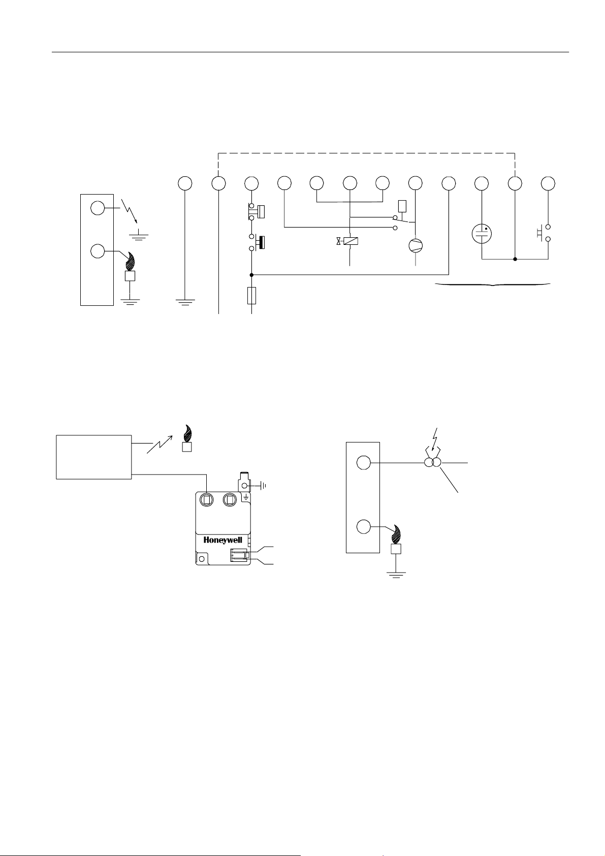
Fig. 1. Dimensional drawing “new style” housing in mm
111
Connector pins suitable
Molex 3001 female connectors
or
18.5
19
29
EN1R--9161 0006R10--NE
69
69
Mounting hole Ø 3.2
Ignition
110
Flame detection
Note: specific housings may deviate from drawing
Fig. 2. Dimensional drawing “old style” housing in mm
2
62
FEATURES IGNITION CONTROLS
Flame supervision.
Built--in 2.5 ... 60 Hz ignition.
Internal or external reset and alarm.
Accurate safety timer.
Supply voltages of 220 ... 240 V in a single product.
Full operating sequence after flame loss.
Extended spark time.
Optional phase neutral independent operation, flame
sensing independent of safety ground potential for
S4565AD ... TD “2000” series and S4575.
Safety time triggered by Air Pressure Switch (APS) for
S4565AD ... TD “2000” series and S4575.
Optional safe separation flame relay output or opto
coupler.
Optional main burner interrupt for S4565 BF, DF, QF, TF.
Volatile or non volatile lock--out according EN 298.
EMC filter optional
Protective impedance flame rod
Under voltage protection
SPECIFICATIONS DIRECT BURNER IGNITION CONTROL S4565A, B, P, Q
Model
Suffix A: atmospheric, direct burner ignition
Suffix B: atmospheric, direct burner ignition, flame relay output
Suffix P: as A except volatile lock--out
Suffix Q: as B except volatile lock--out
Supply voltage
220 ... 240 Vac, 50/60 Hz
Power consumption
4VA
Humidity
90% RH max. at 40 _C
Ambient temperature
0 ... 60 _C
-- 15 ... 60 _C (optional)
Electrical rating (see also note 2.)
Alarm: 220 ... 240 Vac, 50/60 Hz, 1 A, cos ♥ > 0.6 or
1mAmax.
Flame relay contact: 220 ... 240 Vac, 50/60 Hz,
Flame opto coupler: +5 V, 10 kτ
Electrical connection
High voltage spark: 2.8 mm spade terminal
Flame sensing: 4.8 mm spade terminal
PCB connectors: Molex 3003 series suitable for Molex 3001
Housing (degree of protection)
See page 29
Timing (depending on O.S. number)
Self check time (T
1A,cos♥ > 0.6
female cable connector
): 1.5 s
c
Waiting time (T
Safety time (T
Extended spark ignition time: 0 ... T
Flame sensing
Min flame current: 0.9 ←A
Response time on: > 0.2 s
Response time off (T
Ignition
Spark voltage: > 12 kV at 40 pF load
Repetition rate: 2.5 ... 60 Hz (depending on O.S. number)
Max. spark gap: 3.5 mm
Length flame sensing cable
1mmax.
Length ignition cable
0.5 m max.
Length of wiring for external components
1mmax.
Remark
Optional integrated flame relay available with safe separation
or opto coupler with safe separation.
N.C. contact of flame relay has no safe separation.
): 0 ... 30 s
w
): 3.5 ... 55 s
s
FR
s
): < 1 s
(optionally other values available)
WARNING
Opto coupler interface needs a debounce time > 20
ms in order to prevent noise caused by transients on
mains.
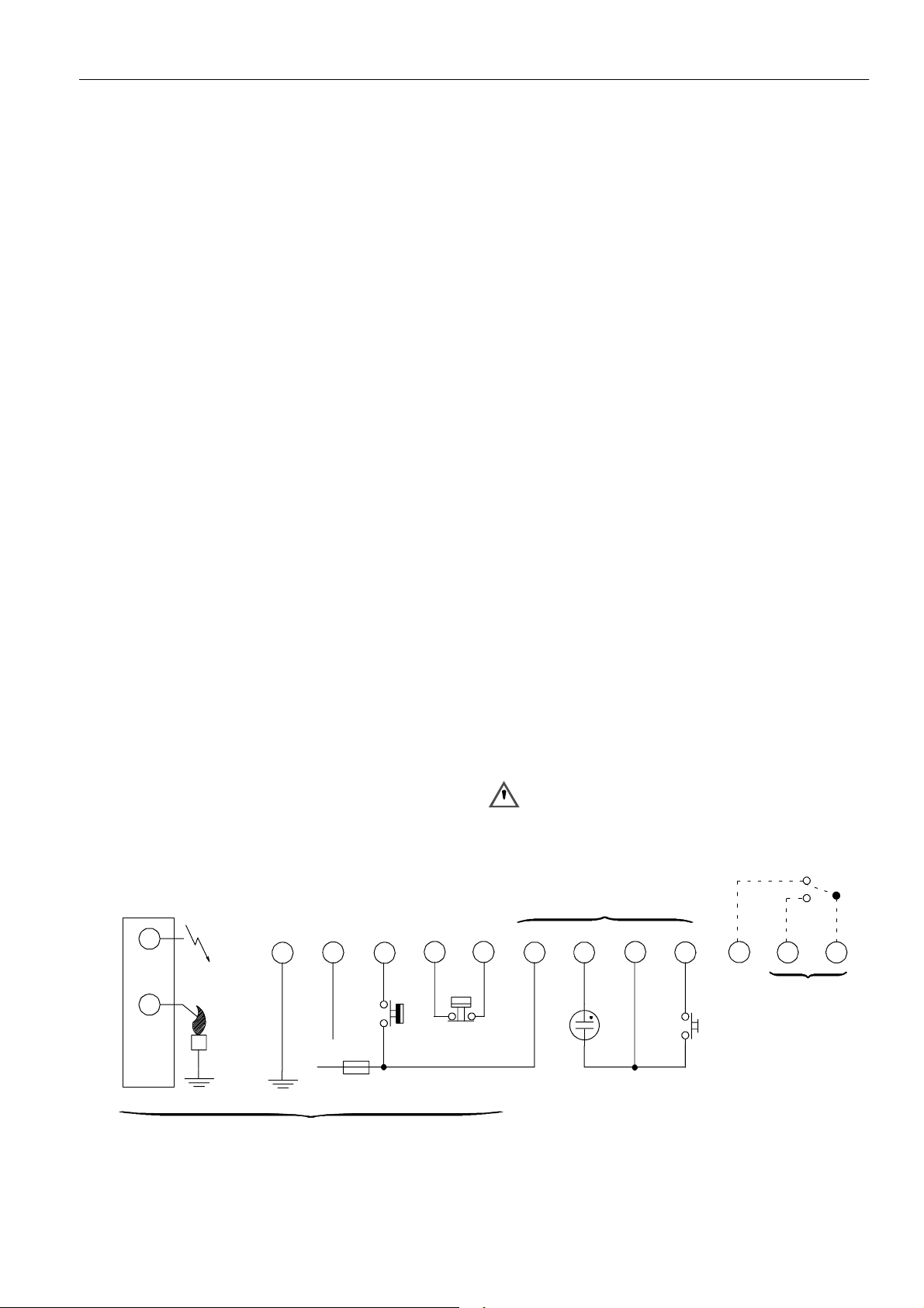
Side connections
12
N
L
All versions
Fig. 3. Connection diagram S4565A, B, P, Q
10
Optional
411
LM
8
3
7
65
*
9
3
Optional
RS
LM -- Limiter
RS -- Reset switch
* See note 2.
** See page 10 fig. 17.
EN1R--9161 0006R10--NE
Optional **
12
SYSTEM OPERATION
General
Lock- out reset
The S4565 ignition control can be reset by either depressing
the internal/external reset button (suffix A and B) or by
interrupting the permanent life (suffix P and Q).
NOTE 1.: If during normal use the reset button is pressed,
the gas valves drop out and the S4565 ignition
control starts a new sequence after releasing the
reset button.
NOTE 2.: If permanent alarm output:
neon indicator with integral resistor >150 kτ
Εmax 1 mA)
NOTE 3.: If an return high limit thermostat is used, the high
limit switch in the application needs a longer return
time than the trial for ignition time of the control.
This in order to provide non volatile lock out.
Suffix A, B, P and Q (see fig. 4.)
When there is a call for heat a self check period (T
waiting period (T
) elapse before built--in igniter and gas valve
w
)plus
c
are switched on.
The ignition spark ignites gas and resulting flame is detected
by the flame rod.
Ignition is switched off after extended ignition time and flame
establishment.
If flame is not established within the safety time (T
), the
s
S4565 ignition control locks out.
If the flame is lost during normal run, the S4565 ignition
control repeats start sequence.
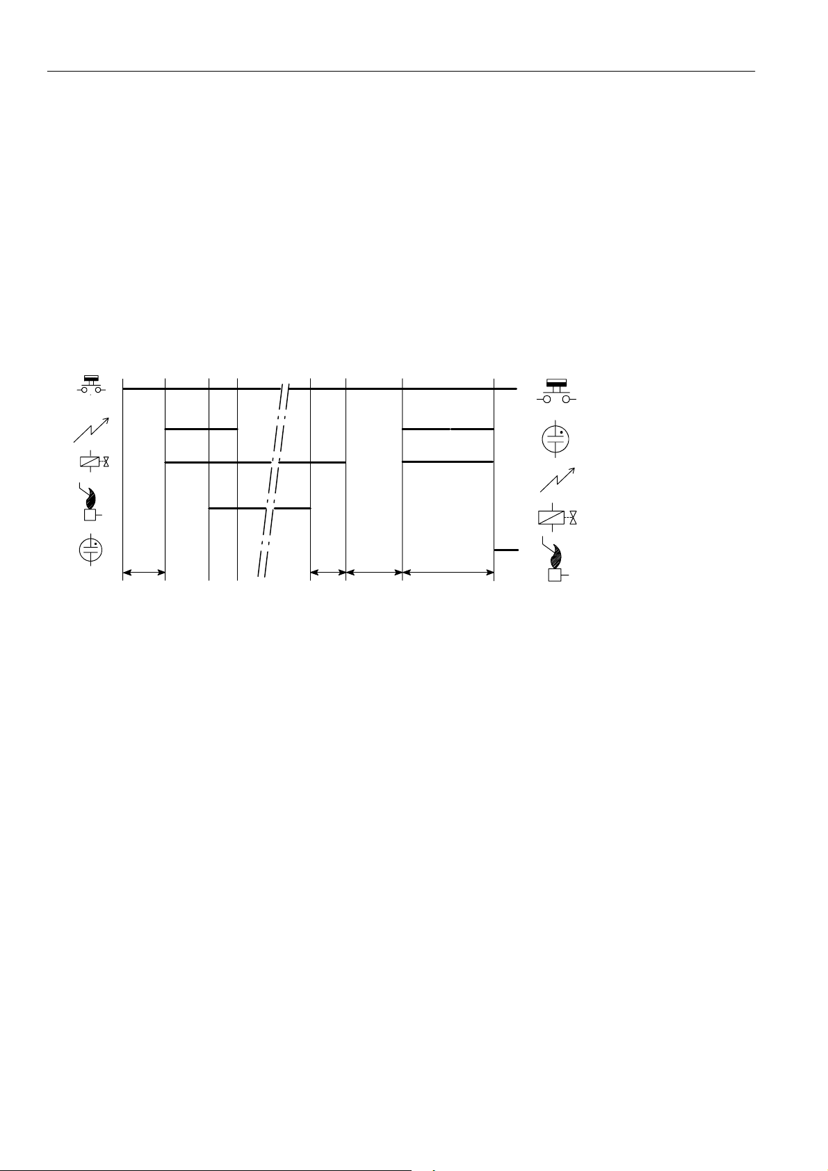
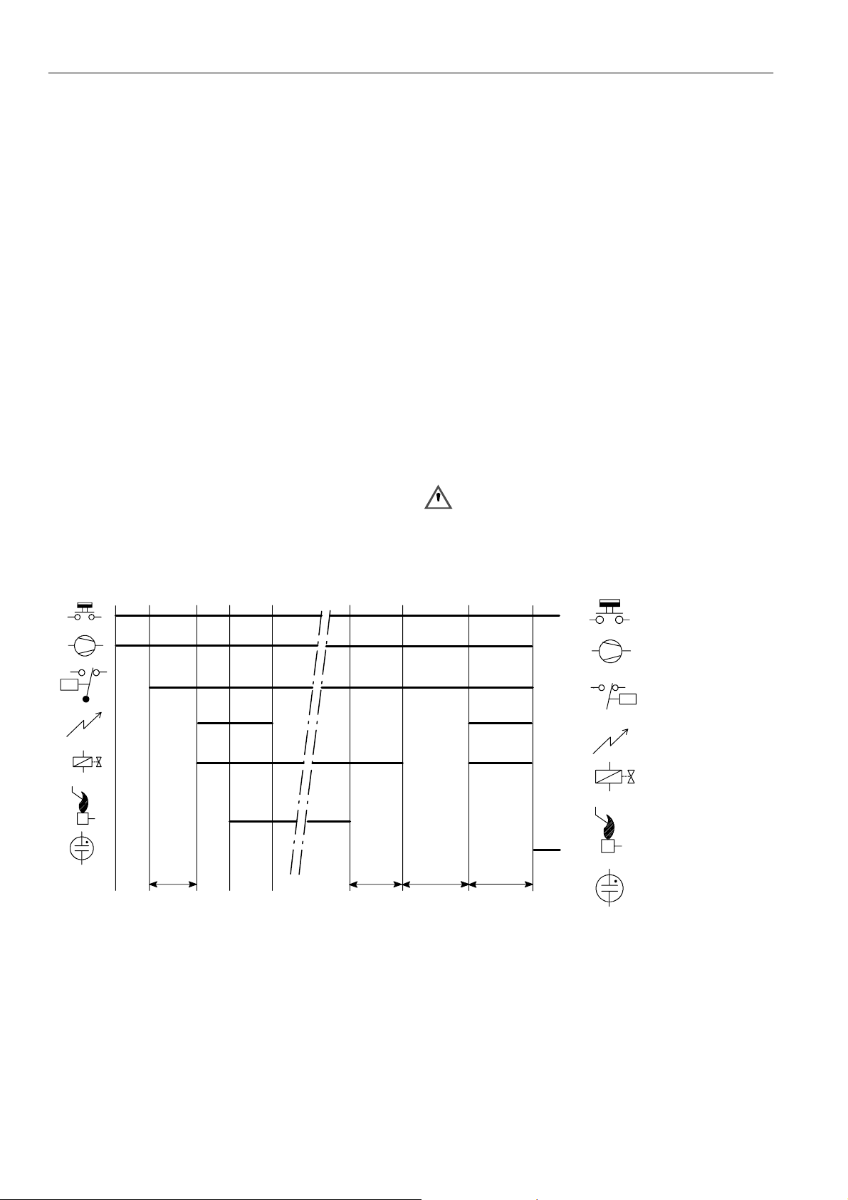
Legend
Thermostat
Alarm
Ignition
Tc+T
Tc+T
w
T
FR
w
T
s
Fig. 4. Functional diagram S4565A, B, P, Q
SPECIFICATIONS IGNITION CONTROL S4565C, D, R, T
Model
Suffix C: fan assisted, direct burner ignition
Suffix D: fan assisted, intermittent pilot burner ignition
including safety timer
Suffix R: as C except volatile lock--out
Suffix T: as D except volatile lock--out
Supply voltage
220 ... 240 Vac, 50/60 Hz
Power consumption
4VA
Humidity
90% RH max. at 40 _C
Ambient temperature
0 ... 60 _C
-- 15 ... 60 _C (optional)
Electrical rating (see also note 5.)
Alarm: 220 ... 240 Vac, 50/60 Hz, 1 A, cos ♥ > 0.6 or
max 1 mA
Fan: 220 ... 240 Vac, 50/60 Hz, 1 A, cos ♥ > 0.6
LPG outdoor valve: 220 ... 240 Vac, 50/60 Hz, 1 A,
cos ♥ > 0.6
External ignition transformer: 220 ... 240 Vac, 50/60 Hz,
1A,cos♥ > 0.6
Electrical connection
High voltage spark: 2.8 mm spade terminal
Optional:
External mains voltage ignition transformer with
2.8 mm spade terminal
Flame sensing: 4.8 mm spade terminal or 2.8 mm spade
terminal for combined high voltage
spark/flame sensing
PCB connectors:Molex 3003 series suitable for Molex 3001
female cable connector
Housing (degree of protection)
See page 29
Timing (depending on O.S. number)
Self check time (T
Prepurge time (T
Safety time (T
c
p
): 3.5 ... 55 s
s
Extended spark ignition time and stabilisation time: 0 ... T
Flame sensing
Min flame current: 0.9 ←A
Response time on: > 0.2 s
Response time off (T
): 0, 1.5 or 2 s
): 0 ... 30 s
(dependent on elaps of safety time)
): < 1 s
FR
(optionally other values available)
Gas valve
Flame rod
s
EN1R--9161 0006R10--NE
4
Ignition
Spark voltage: > 12 kV at 40 pF load
Repetition rate: 2.5 ... 60 Hz (depending on O.S. number)
Max spark gap: 3.5 mm
Length flame sensing cable
1mmax.
Length ignition cable
0.5 m max.
Length of wiring for external components
1mmax.
Side connections**
ignition control
12
Special applications
input
11
10
8
LM
7
¯
LPG
N
P -- Air proving switch
LM -- Limiter
N
L
RS -- Reset switch
* See note 5.
** Alternative side connection for models with combined flame
detection/high voltage. See page 5 fig. 6.
Fig. 5. Connection diagram S4565C, D, R, T
Side connection
230 Vac
21
569
P
3
¯
24
*¯
1
RS
N
Optional
N
Ignition transformer
AT7030
N
L
Fig. 6. Alternative side connection for models with
combined flamedetection/high voltage.
Ph1
Ph2
Fig. 7. Alternative side connection for models with flame
sense input + 230 Vac output for external ignition
transformer
5
EN1R--9161 0006R10--NE
SYSTEM OPERATION
General
Lock- out reset
The S4565 can be reset by either depressing the
internal/external reset button (suffix C and D) or by
interrupting the permanent life (suffix R and T).
NOTE 4.: If during normal use the reset button is pressed,
he gas valves close and the S4565 ignition control
starts a new sequence after releasing the reset
button.
NOTE 5.: If permanent alarm output:
neon indicator with integral resistor >150 kτ
Suffix C and R (see fig. 8.)
When there is a call for heat the fan starts running through the
no air position of the air proving switch.
If an external LPG valve is connected, this will be energized.
When sufficient air flow is proven by the air proving switch, a
self check period (T
) and prepurge period (Tp)elapse before
c
the gas valve and built--in ignition or external ignition
transformer (optional) are switched on.
The ignition spark ignites gas and resulting flame is detected
by the flame rod.
Internal or external ignition is switched off.
After flame establishment a predetermined, extended ignition
time can be included.
If flame is not established within the safety time (T
S4565 ignition control locks out.
Εmax 1 mA)
), the
s
If the flame is lost during normal run, the S4565 ignition
control repeats the start sequence with prepurge.
If no air is proven by the air proving switch within the prepurge
time (T
running.
), the ignition control stays in waiting mode with fan
p
Suffix D and T (see fig. 9.)
When there is a call for heat the fan starts running through the
no air position of the air proving switch.
If an external LPG valve is connected, this will be energized.
When sufficient air flow is proven by the air proving switch, a
self check period (T
the pilot gas valve and built-- in ignition or external ignition
) and prepurge period (Tp)elapses before
c
transformer (optional) are switched on.
The ignition spark ignites pilot gas and resulting flame is
detected by the flame rod.
Internal or external ignition is switched off.
After flame establishment a predetermined, extended ignition
time can be included and flame establishment and the main
valve is switched on.
If flame is not established within the safety time (T
), the
s
S4565 ignition control locks out.
If the flame is lost during normal run, the S4565 ignition
control repeats start sequence at prepurge.
If no air is proven by the air proving switch within the prepurge
time (T
running.
), the ignition control stays in waiting mode with fan
p
WARNING
Do not interchange air proving switch wiring in order to
prevent malfunctioning
Legend
Thermostat
Fan
P
P
¯
Air proving switch
Ignition
Main valve
Flame rod
Tc+T
p
T
FR
Tc+T
p
T
s
Alarm
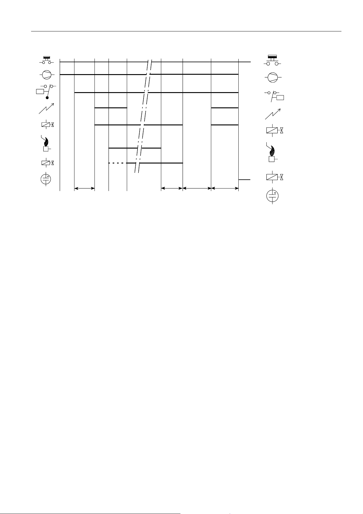
Fig. 8. Functional diagram S4565C, R
EN1R--9161 0006R10--NE
6
h
Legend
Thermostat
Fan
P
PV
MV
Tc+T
p
T
FR
T
c+Tp
T
s
Fig. 9. Functional diagram S4565D, T
SPECIFICATIONS DIRECT BURNER IGNITION CONTROL
S4565AD, BD, CD, DD, PD, QD, RD, TD “1000- SERIES”
Model
Suffix AD: atmospheric, direct burner ignition
Suffix BD: as AD but with flame relay output
Suffix CD: fan assisted, direct burner ignition
Suffix DD: as CD but with flame relay output
Suffix PD: as AD except volatile lock--out
Suffix QD: as BD except volatile lock--out
Suffix RD: as CD except volatile lock--out
Suffix TD: as DD except volatile lock--out
Supply voltage
220 ... 240 Vac, 50/60 Hz
Power consumption
4VA
Humidity
90% RH max. at 40 _C non condensing
Ambient temperature
0 ... 60 _C
-- 15 ... 60 _C (optional)
Electrical rating (see also note 8.)
Alarm: 220 ... 240 Vac, 50/60 Hz, 1 A, cos ♥ > 0.6 or max 1mA
Fan: 220 ... 240 Vac, 50/60 Hz, 1 A, cos ♥ >0.6
Flame relay contact: 220 ... 240 Vac, 50/60 Hz, 1 A,
cos ♥ >0.6
Flame opto coupler: +5 V, 10 kτ
LPG valve: 220 ... 240 Vac, 50/60 Hz,1 A max, cos ♥ >0.6
Electrical connection
High voltage spark: 2.8 x 0.5 mm spade terminal
Flame sensing: 4.8 x 0.8 mm spade terminal
PCB connectors: Molex 3003 series suitable for Molex 3001
Housing (degree of protection)
See page 29
Timing (depending on O.S. number)
Self check time (T
Waiting time (T
Safety time (T
): 1.5 s
c
): 0 ... 30 s
w
): 3.5 ... 25 s
s
Extended spark ignition time: 0 ... T
Flame sensing
Min flame current: 0.9 ←A
Response time on: > 0.2 s
Response time off (T
FR
Ignition
Spark voltage: >12 kV at 40 pF load
Repetition rate: 2.5 ... 60 Hz (depending on O.S. number)
Max. spark gap: 3.5 mm
Optional external ignition circuit: 220 ... 240 V (at no load),
Length flame sensing cable
1mmax.
Length ignition cable
0.5 m max.
Length of wiring for external components
1mmax.
P
¯
Air proving switc
Ignition
Pilot valve
PV
Flame rod
Main valve
MV
Alarm
female cable connector
(dependent on elaps of safety time)
s
): < 1 s
(depending on O.S. number)
single phase rectified, max 2 VA
7
EN1R--9161 0006R10--NE
Remark
Optional integrated flame relay available with safe separation
or opto coupler with safe separation.
N.C. contact of flame relay has no safe separation.
Side connections **
WARNING
Opto coupler interface needs a debounce time > 20
ms in order to prevent noise caused by transients on
mains.
Optional
Side connections **
10
9
LM
8
712
*
65
RS
N
L
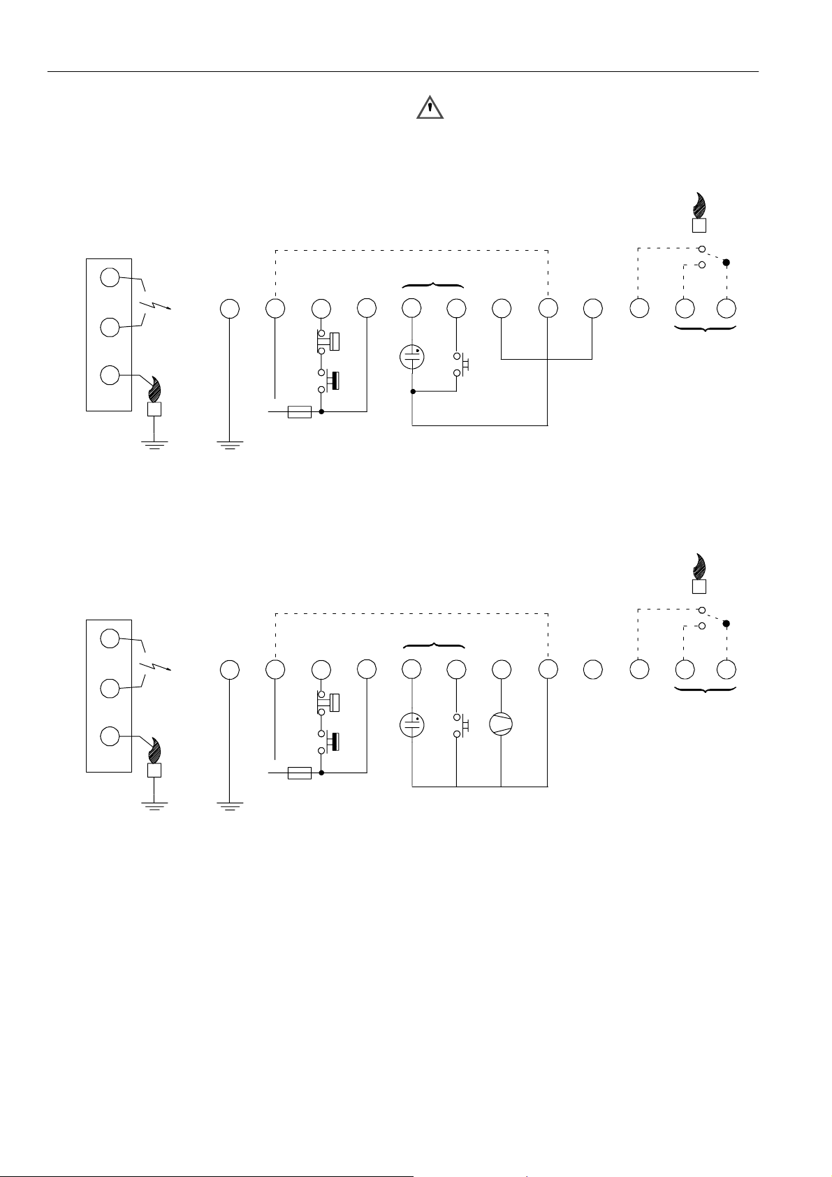
Fig. 10. Connection diagram S4565AD and BD
Optional
10
9
LM
8
712
*
65
411
3
Optional ***
LM -- Limiter
RS -- Reset switch
* See note 8.
** See page 10 fig. 16.
*** See page 10 fig. 17.
411
3
Optional
Optional ***
12
12
Fig. 11. Connection diagram S4565BD and QD “1000” series for gas/air application
EN1R--9161 0006R10--NE
N
L
RS
* See note 8.
** See page 10 fig. 16.
*** See page 10 fig. 17.
8

Side connections **
Side connections
10
9
LM
8
712
*
65
RS
C
N
L
N
Fig. 12. Connection diagram S4565CD and DD
10
9
LM
8
712
*
65
+--
411
P
NC
3
Optional
Optional ***
12
¯
NO
P -- Air proving switch
LM -- Limiter
RS -- Reset switch
* See note 8.
** See page 10. fig. 16.
*** See page 10 fig. 17.
411
3
Optional ***Optional
12
Side connections **
N
L
N
Fig. 13. Connection diagram S4565QD with external ignition circuit
10
98 65
LM
712
*
N
L
Fig. 14. Connection diagram S4565PD and QD
LM -- Limiter
RS -- Reset switch
* See note 8.
*** See page 10 fig. 17.
411
3
Optional
Optional ***
LM -- Limiter
* See note 8.
** See page 10. fig. 16.
*** See page 10 fig. 17.
12
9
EN1R--9161 0006R10--NE

Side connections **
Side connections
10
9
LM
8
712
*
65
N
L
Fig. 15. Connection diagram S4565RD and TD
10k
411
P
NC
¯
C
NO
3
Optional
Optional ***
P -- Air proving switch
LM -- Limiter
RS -- Reset switch
* See note 8.
** See page 10. fig. 16.
*** See page 10 fig. 17.
21
Flame
output
+--
5V
12
Fig. 16. Alternative side connection if sparking to ground
Fig. 17. Connection for opto coupler output
EN1R--9161 0006R10--NE
10

SYSTEM OPERATION
General
The S4565AD, BD, CD, DD, PD, QD, RD, TD ignition control
can provide both closed--loop sparking and sparking to
ground.
If the S4565AD, BD, CD, DD, PD, QD, RD, TD will be used in
sparking to ground applications, the upper spark tab has to be
grounded.
Lock- out reset
The S4565 can be is reset by either depressing the
internal/external reset button (suffix AD, BD, CD and DD) or
by interrupting the permanent life (suffix PD, QD, RD and TD).
NOTE 6.: When first starting, the inition control can be in the
NOTE 7.: If during normal use the reset button is pressed,
NOTE 8.: If permanent alarm output:
Suffix AD and PD (see fig. 18.)
When there is a call for heat a self check period (T
waiting period (T
valve are switched on.
The ignition spark ignites gas and resulting flame is detected
by the flame rod.
After flame establishment a predetermined, extended ignition
time can be included.
If flame is not established within the safety time (T
lock-- out condition; reset the ignition control.
After a reset an extended waiting time will occur.
the gas valves close and the S4565 ignition
control starts a new sequence after releasing the
reset button.
neon indicator with integral resistor >150 kτ
Εmax 1 mA)
)plus
) elapses before the built--in igniter and gas
w
c
), the
s
S4565 ignition control locks out.
If the flame is lost during normal run, the S4565 ignition
control repeats start sequence.
Suffix BD and QD (see fig. 19.)
As AD and PD except flame relay contact or opto is closed
after flame detection.
Suffix CD and RD (see fig. 20.)
When there is a call for heat the fan starts running through the
no air position of the air proving
period (T
proven by the air proving switch, the built--in igniter and gas
) plus waiting period (Tw). When sufficient air flow is
c
switch after a self check
valve are switched on.
The ignition spark ignites gas and resulting flame is detected
by the flame rod.
After flame establishment a predetermined, extended ignition
time can be included.
If flame is not established within the safety time (T
S4565 ignition control locks out.
), the
s
If the flame is lost during normal run, the S4565 ignition
control repeats start sequence.
If no air is proven by the air proving switch within the safety
time (T
), the ignition control locks out.
s
Suffix DD and TD (see fig. 21.)
As CD and RD except flame relay contact or opto is closed
after flame detection.
Gas/air application
For gas/air application without dynamic aircheck, the
S4565AD, BD, PD or QD can be used.
In this application the fan is connected between pin 4 and 5
and will start when a call for heat is present. The waiting
period now acts as a prepurge time.
When the call for heat disappears or when the ignition control
goes in lock --out, the fan will be switched off.
Tc+T
Legend
Thermostat
Ignition
Gas valve
Flame rod
w
T
FR
Tc+T
w
T
s
Alarm
Fig. 18. Functional diagram S4565AD, PD
11
EN1R--9161 0006R10--NE

Legend
Thermostat
LPG
LPG
LPG valve
Ignition
Gas valve
Flame rod
Flame relay contact
Tc+T
T
w
FR
Tc+T
w
T
s
Alarm
Fig. 19. Functional diagram S4565BD, QD
Legend
Thermostat
Fan
P
P
Air proving switch
Tc+T
Ignition
Gas valve
Flame rod
Tc+T
w
T
FR
w
T
s
Alarm
Fig. 20. Functional diagram S4565CD, RD
EN1R--9161 0006R10--NE
12

Legend
Thermostat
Fan
P
Tc+T
w
T
FR
Tc+T
w
T
s
Fig. 21. Functional diagram S4565DD, TD
SPECIFICATIONS DIRECT BURNER IGNITION CONTROL
S4565AD, BD, CD, DD, PD, QD, RD, SD, TD “2000” SERIES
Model
Suffix AD: atmospheric, direct burner ignition
Suffix BD: as AD but with flame relay output
Suffix CD: fan assisted, direct burner ignition
Suffix DD: as CD but with flame relay output
Suffix PD: as AD except volatile lock--out
Suffix QD: as BD except volatile lock--out
Suffix RD: as CD except volatile lock--out
Suffix SD: ignition circuit and rectifier only
Suffix TD: as DD except volatile lock--out
Supply voltage
230 ... 240 Vac, 50/60 Hz
Power consumption
4VA
Humidity
90% RH max. at 40 _C
Ambient temperature
0 ... 60 _C
-- 15 ... 60 _C (optional)
Electrical rating (see also note 8.)
Alarm: 230 ... 240 Vac, 50/60 Hz, output max 1mA
(e.g. neon light with internal resistor > 150 k τ)
Fan: 230 ... 240 Vac, 50/60 Hz, max 1 A, max cos ♥ >0.6
Hour counter: 230 ... 240 Vac, 50/60 Hz, max 1 A, cos ♥ >0.6
Flame relay contact: 230 ... 240 Vac, 50/60 Hz, max 1 A,
cos ♥ >0.6
Flame opto coupler: +5 V, 10 kτ
Electrical connection
High voltage spark: 2.8 mm spade terminal
optional: 4 mm round terminal in spark to ground
application
Flame sensing: 4.8 mm spade terminal
PCB connectors: Molex 3003 series suitable for Molex 3001
Housing (degree of protection)
See page 29
Timing (depending on O.S. number)
Self check time (T
Waiting time (T
Safety time (T
): 0 ... 2 s
c
): 0 ... 30 s
w
): 3.5 ... 55 s
s
Extended spark ignition time: 0 ... T
Flame sensing
Min flame current:
for optional phase independent systems: 0.5 ←A
for phase dependent systems: 0.9 ←A
Response time on: > 0.2 s
Response time off (T
FR
Ignition
Spark voltage: > 12 kV at 40 pF load
Repetition rate: 2.5 ... 60 Hz (depending on O.S. number)
Max. spark gap: 3.5 mm
Length flame sensing cable
1mmax.
P
Air proving switch
Ignition
Gas valve
Flame rod
Flame relay contact
Alarm
female cable connector
(dependent on elaps of safety time)
s
): < 1 s
(optionally other values available)
13
EN1R--9161 0006R10--NE

Length ignition cable
0.5 m max.
Length of wiring for external components
1mmax.
Remark
Optional integrated flame relay available with safe separation
or opto coupler with safe separation.
N.C. contact of flame relay has no safe separation.
Side connections *
WARNING
Opto coupler interface needs a debounce time > 20
ms in order to prevent noise caused by transients on
mains.
Side connections *
10
9
8
712
65
h
LM
RS
L
Fig. 22. Connection diagram S4565AD and BD “2000 “series
10
9
8
712
65
LM
411
3
Optional
Optional **
12
N
LM -- Limiter
RS -- Reset switch
h -- Hour counter
* See page 16. fig. 28.
** See page 10 fig. 17.
h and RS and alarm are optional
411
N
3
Optional
Optional **
12
EN1R--9161 0006R10--NE
LM output
LM -- Limiter
RS -- Reset switch
* See page 16. fig. 28.
RS
** See page 10 fig. 17.
L
RS and alarm are optional
Fig. 23. Connection diagram S4565AD and BD “2000 “series (optional )
14

Side connections *
Side connections *
10
9
8
712
P
65
LM
RS
L
Fig. 24. Connection diagram S4565CD and DD “2000”series
10
9
8
712
65
h
411
N
3
Optional
Optional **
LM -- Limiter
RS -- Reset switch
P -- Air pressure switch
* See page 16. fig. 28.
** See page 10 fig. 17.
RS and alarm optional
411
3
Optional
Optional **
N
12
12
Side connections *
LM
L
Fig. 25. Connection diagram S4565PD and QD “2000”series
10
9
8
712
P
65
LM
L
Fig. 26. Connection diagram S4565RD and TD “2000”series
LM -- Limiter
h -- Hour counter
* See page 16. fig. 28.
** See page 10 fig. 17.
h is optional
411
3
Optional
Optional **
N
LM -- Limiter
P --Air proving switch
* See page 16. fig. 28.
** See page 10 fig. 17.
12
15
EN1R--9161 0006R10--NE

Side connections
10
Void
9
N
Fig. 27. Connection diagram S4565SD “2000” series
Side connections
Fig. 28. Alternative side connection if sparking to ground
Side connection
Fig. 29. Alternative side connection in case of single rod
SYSTEM OPERATION
General
The S4565AD, BD, CD, DD, PD, QD, RD, TD ignition control
can provide both closed--loop sparking and sparking to
ground.
The S4565SD ignition circuit and rectifier provides
closed-- loop sparking.
3
L
ignition
Not
8
712
65
411
L
valves
used
Lock- out reset
The S4565 can be is reset by either depressing the
internal/external reset button (suffix AD, BD, CD and DD) or
by interrupting the permanent life (suffix PD, QD, RD and TD).
NOTE 9.: If during normal use the reset button is pressed,
the gas valves close and the S4565 starts a new
sequence after releasing the reset button.
Suffix AD and PD (see fig. 30.)
When there is a call for heat a self check period (T
waiting period (T
) elapse before the built--in igniter and gas
w
)plus
c
valve are switched on.
The ignition spark ignites gas and resulting flame is detected
by the flame rod.
After flame establishment a predetermined, extended ignition
time can be included.
If flame is not established within the safety time (T
), the
s
S4565 ignition control locks out.
If the flame is lost during normal run, the S4565 ignition
control repeats start sequence.
Suffix BD and QD (see fig. 31.)
As AD and PD except flame relay contact or opto is activated
after flame detection.
NOTE 10.: The hour counter is energized when the valve is
energized. It can be used as an output signal.
Suffix CD and RD (see fig. 32.)
When there is a call for heat, self check period (T
waiting period (T
) elapse when the air proving switch is in the
w
)plus
c
no air position.
After T
the fan starts running.
c+Tw
When sufficient air flow is proven by the air proving switch, the
built--in igniter and gas valve are switched on.
The ignition spark ignites gas and resulting flame is detected
by the flame rod.
After flame establishment a predetermined, extended ignition
time can be included.
If flame is not established within the safety time (T
S4565 ignition control locks out.
), the
s
If the flame is lost during normal run, the S4565 ignition
control repeats start sequence.
12
EN1R--9161 0006R10--NE
16

If no air is proven by the air proving switch, the ignition control
stays waiting (optional lock out on no air can be included).
Suffix DD and TD (see fig. 33.)
As CD and RD except flame relay contact or opto is activated
after flame detection.
Suffix SD (see fig. 27.)
If line voltage is applied between pin 5 (line valves) and
pin 9 (N), the gas valve is switched on.
If the line voltage is applied between pin 4 (line ignition) and
pin 9 (N) the build in igniter is switched on.
The igniter circuit is fed during the negative half wave of the
mains.
Pin 8 is present but not intended for use. It is connected with a
resistor (100 τ)topin5.
Ignition circuit must be on shorter than 10 s in an application
with single ignition trial.
Gas/air application
For gas/air application without dynamic aircheck, the
S4565AD, BD, PD or QD can be used.
In this application the fan is connected between pin 4 and 5
and will start when a call for heat is present. The waiting
period now acts as a prepurge time.
When the call for heat disappears or when the ignition control
goes in lock --out, the fan will be switched off.
Legend
Thermostat
Ignition
Gas valve
Flame rod
Tc+T
Tc+T
w
T
FR
Tc+T
w
T
s
Alarm
Fig. 30. Functional diagram S4565AD, PD “2000”series
Legend
Thermostat
Ignition
Gas valve
Flame rod
Flame relay contact
T
w
FR
Tc+T
w
T
s
Alarm
Fig. 31. Functional diagram S4565BD, QD “2000”series
17
EN1R--9161 0006R10--NE

Legend
Thermostat
Fan
P
P
Air proving switch
Ignition
Gas valve
Flame rod
Tc+T
w
Tc+T
T
FR
w
T
s
Alarm
Fig. 32. Functional diagram S4565CD, RD “2000”series
Legend
Thermostat
Fan
P
P
Air proving switch
Ignition
Gas valve
Flame rod
Flame relay contact
Tc+T
w
T
FR
Tc+T
w
T
s
Alarm
Fig. 33. Functional diagram S4565DD, TD “2000”series
SPECIFICATIONS IGNITION CONTROL S4565AF, BF, CF, DF, PF, QF, RF, TF
Model
Suffix AF: atmospheric, direct burner ignition
Suffix BF: atmospheric, intermittent pilot burner ignition
including safety timer
Suffix CF: fan assisted, direct burner ignition
Suffix DF: fan assisted, intermittent pilot burner ignition
including safety timer
Suffix PF: as AF except volatile lock--out
Suffix QF: as BF except volatile lock--out
Suffix RF: as CF except volatile lock--out
Suffix TF: as DF except volatile lock--out
Supply voltage
220 ... 240 Vac, 50/60 Hz
Power consumption
4VA
EN1R--9161 0006R10--NE
18

Humidity
90% RH max. at 40 _C
Ambient temperature
0 ... 60 _C
-- 15 ... 60 _C (optional)
Electrical rating (see also note 12.)
Alarm: 220 ... 240 Vac, 50/60 Hz, 1 A, cos ♥ >0.6or
max 1mA
Fan: 220 ... 240 Vac, 50/60 Hz, 1 A, cos ♥ >0.6
LPG outdoor valve: 220 ... 240 Vac, 50/60 Hz, 1 A,
cos ♥ >0.6
Electrical connection
High voltage spark: 2.8 mm spade terminal
Optional: 4 mm round terminal
Flame sensing: 4.8 mm spade terminal or 2.8 mm spade
terminal for combined high voltage
spark/flame sensing
PCB connectors:Molex 3003 series suitable for Molex 3001
female cable connector
Housing (degree of protection)
See page 29
Timing (depending on O.S. number)
Self check time (T
Waiting time (T
): 1.5 s
c
): 0 ... 30 s
w
Safety time (T
Extended spark ignition time and stabilisation time: 0 ... T
): 3.5 ... 55 s
s
(dependent on elaps of safety time)
s
External main burner interrupt
Max open contact voltage 24 V, max current 15 mA
A low voltage relay is suitable.
An opto coupler e.g. CNY17-- 3 is also possible
A flame indicating series LED (see connection diagram) will
conduct min 0.85 mA if the contact is open and minimal
3.5 mA if the contact is closed.
Flame sensing
Min flame current: 0.9 ←A
Response time on: > 0.2 s
Response time off (T
):<1s
FR
Ignition
Spark voltage: > 12 kV at 40 pF load
Repetition rate: 2.5 ... 60 Hz (depending on O.S. number)
Max spark gap: 3.5 mm
Length flame sensing cable
1mmax.
Length ignition cable
0.5 m max.
Length of wiring for external components
1mmax.
Side connections**
12
11
10
8
7
LM
LPG
P -- Air proving switch
LM -- Limiter
N
L
RS -- Reset switch
* See note 12.
** Alternative side connection for models with combined flame
detection/high voltage. See page 5 fig. 6.
Fig. 34. Connection diagram S4565AF, BF, PF, QF
569
G
3
24
*
1
RS
Optional
19
EN1R--9161 0006R10--NE

Side connections**
12
11
10
8
7
569
3
24
1
Side connections**
LM
P -- Air proving switch
LM -- Limiter
N
L
RS -- Reset switch
* See note 12.
** Alternative side connection for models with combined flame
detection/high voltage. See page 5 fig. 6.
Fig. 35. Connection diagram S4565CF, DF, RF, TF
12
11
10
8
7
LM
22 K
CNY 17--3
*
RS
P
¯
Optional
569
3
24
*
1
RS
N
L
Fig. 36. Connection diagram S4565DF, TF with external main burner interrupt
SYSTEM OPERATION
General
Lock- out reset
The S4565 can be is reset by either depressing the
internal/external reset button (suffix AF, BF, CF and DF) or by
interrupting the permanent life (suffix PF, QF, RF, and TF).
P
Optional
P -- Air proving switch
LM -- Limiter
RS -- Reset switch
* See note 12.
** Alternative side connection for models with combined flame
detection/high voltage. See page 5 fig. 6.
NOTE 11.: If during normal use the reset button is pressed,
the gas valves close and the S4565 ignition
control starts a new sequence after releasing the
reset button.
NOTE 12.: If permanent alarm output:
neon indicator with integral resistor >150 kτ
Εmax 1 mA)
EN1R--9161 0006R10--NE
20

NOTE 13.: If an external LPG valve and gas pressure switch
are connected, the LPG valve is energized after
call for heat.
The ignition control stays in waiting mode, until the
gas pressure switch is closed.
If during normal operation the gas pressure switch
opens, the gas valves will not be closed.
Suffix AF and PF (see fig. 37.)
When there is a call for heat a self check period (T
waiting period (T
valve are switched on.
) elapses before built--in igniter and gas
w
)plus
c
The ignition spark ignites gas and resulting flame is detected
by the flame rod.
After flame establishment a predetermined, extended ignition
time can be included.
If flame is not established within the safety time (T
S4565 ignition control locks out.
), the
s
If the flame is lost during normal run, the S4565 ignition
control repeats start sequence.
Suffix BF and QF (see fig. 38.)
When there is a call for heat a self check period (T
waiting period (T
valve are switched on.
) elapses before built--in igniter and pilot gas
w
)plus
c
The ignition spark ignites pilot gas and resulting flame is
detected by the flame rod.
After flame establishment a predetermined, extended ignition
time can be included then the main valve is switched on.
If flame is not established within the safety time (T
S4565 ignition control locks out.
), the
s
If the flame is lost during normal run, the S4565 ignition
control repeats start sequence.
Suffix CF and RF (see fig. 39.)
When there is a call for heat the fan starts running through the
no air position of the air proving switch after a self check
period (T
When sufficient air flow is proven by the air proving switch, the
) plus waiting period (Tw).
c
built--in igniter and gas valve are switched on.
The ignition spark ignites gas and resulting flame is detected
by the flame rod.
Ignition is switched off after a predetermined extended ignition
time and flame establishment.
If flame is not established within the safety time (T
), the
s
S4565 ignition control locks out.
If the flame is lost during normal run, the S4565 ignition
control repeats start sequence.
If no air is proven by the air proving switch within the safety
time (T
), the ignition control locks out.
s
Suffix DF and TF (see fig. 40.)
When there is a call for heat the fan starts running through the
no air position of the air proving switch after a self check
period (T
) plus waiting period (Tw).
c
When sufficient air flow is proven by the air proving switch, the
built--in igniter and pilot gas valve are switched on.
The ignition spark ignites pilot gas and resulting flame is
detected by the flame rod.
Ignition is switched off after a predetermined extended ignition
time (T
)and flame establishment and then the main valve is
ext
switched on.
If flame is not established within the safety time (T
), the
s
S4565 ignition control locks out.
If the flame is lost during normal run, the S4565 ignition
control repeats start sequence.
If no air is proven by the air proving switch within the safety
time (T
), the ignition control locks out.
s
If the internal main burner interrupt is activated (relay contact
opened or opto transistor de--activated) the main valve drops
off, but the pilot flame stays present.
LPG
Tc+T
Legend
Thermostat
LPG outdoor valve
LPG
Ignition
Gas valve
Tc+T
w
T
FR
w
T
s
Flame rod
Alarm
Fig. 37. Functional diagram S4565AF, PF
21
EN1R--9161 0006R10--NE

Legend
Thermostat
LPG
PV
MV
LPG outdoor valve
LPG
Ignition
Pilot valve
PV
Flame rod
Main valve
MV
Tc+T
w
T
stab
Tc+T
T
FR
w
T
s
Alarm
Fig. 38. Functional diagram S4565BF, QF
Legend
Thermostat
Fan
P
P
Air proving switch
Tc+T
Ignition
Main valve
Flame rod
w
Tc+T
T
FR
w
T
s
Alarm
Fig. 39. Functional diagram S4565CF, RF
EN1R--9161 0006R10--NE
22

Legend
Thermostat
Fan
P
Air proving switch
P
Ignition
Pilot valve
PV
PV
Flame rod
MV
Main valve
MV
MBI
Tc+T
w
T
ext
Tc+T
T
FR
w
T
s
MBI
Main burner interrupt
Alarm
Fig. 40. Functional diagram S4565DF, TF
SPECIFICATIONS DIRECT BURNER IGNITION CONTROL S4575A, B, P, Q
Model
Suffix A: atmospheric, direct burner ignition
Suffix B: as A but with flame relay output
Suffix P: as A except volatile lock--out
Suffix Q: as B except volatile lock--out
Supply voltage
230 ... 240 Vac, 50/60 Hz (--15%, +10%)
Power consumption
4VA
Humidity
90% RH max. at 40 _C
Ambient temperature
0 ... 60 _C
-- 15 ... 60 _C (optional)
Electrical rating
Alarm: 230 ... 240 Vac, 50/60 Hz, max 1 mA
Fan: 230 ... 240 Vac, 50/60 Hz, 1 A, cos ♥ >0.6
Flame relay contact: 230 ... 240 Vac, 50/60 Hz, 1 A,
cos ♥ >0.6
Flame opto coupler: +5 V, 10 kτ
Electrical connection
Hot surface ignition relay: 2.8 mm spade terminal
Flame sensing: 4.8 mm spade terminal
PCB connectors: Molex 3003 series suitable for Molex 3001
female cable connector
Housing (degree of protection)
See page 29
Timing (depending on O.S. number)
Self check time (T
Glowing time (T
Safety time (T
Extended ignition time: 0 ... T
): 1.5 s
c
): 0 ... 30 s
g
): 3.5 ... 25 s
s
s
(dependent on elaps of safety time)
Flame sensing
Min flame current:
for optional phase independent versions: 0.5 ←A
for phase dependent versions: 0.9 ←A
Response time on: > 0.2 s
Response time off (T
FR
): < 1 s
Hot surface ignition relay
Free contact: 230 ... 240 Vac, 2 A, cos ♥ =1
24 Vac, 2 A, cos ♥ =1
120 Vac, 2 A, cos ♥ =1
WARNING
Hot Surface Igniter (HSI) needs to be supplied from a
floating winding of a transformer in order to quarantee
reliable flame detection.
Length flame sensing cable
1mmax.
23
EN1R--9161 0006R10--NE

Length of wiring for external components
1mmax.
Remark
Optional integrated flame relay available with safe separation
or opto coupler with safe separation.
N.C. contact of flame relay has no safe separation.
Side connections
24 ... 240 V
WARNING
Opto coupler interface needs a debounce
time > 20 ms in order to prevent noise caused by
transients on mains.
Side connections
L
24 ... 240 V
RS
10
9
LM
8
712
65
Fig. 41. Connection diagram S4575A, B, P and Q
411
3
OptionalOptional
LM -- Limiter
RS -- Reset switch
* See page 10 fig. 17.
N
Reset switch and alarm
are optional
12
*
EN1R--9161 0006R10--NE
10
9
8
712
65
411
3
12
Optional
RS
LM
10k
5V
L
N
+--
LM -- Limiter
RS -- Reset switch
Fig. 42. Connection diagram S4575B 1009
24

SYSTEM OPERATION
General
The S4575A, B, P, Q ignition controls can provide hot surface
ignition.
The Hot Surface Igniter (HSI is connected to a floating
winding of a transformer (see fig 41., 42.).
Lock- out reset
The S4575 can be is reset by either depressing the
internal/external reset button (suffix A and B) or by interrupting
the permanent life (suffix P and Q).
NOTE 14.: If during normal use the reset button is pressed,
the gas valves close and the S4575 ignition
control starts a new sequence after releasing the
reset button.
NOTE 15.: If permanent alarm output: neon indicator with
integral resistor >150 kτΕmax 1 mA)
Suffix A and P (see fig. 43.)
When there is a call for heat the HSI starts glowing during
glowing time (T
After the glowing time (T
The igniter ignites gas and resulting flame is detected by the
).
g
) the gas valve is switched on.
g
flame rod.
After flame establishment a predetermined, extended ignition
time can be included.
If flame is not established within the safety time (T
S4575 ignition control locks out.
), the
s
If the flame is lost during normal run, the S4575 ignition
control repeats start sequence.
Suffix B and Q (see fig. 44.)
As suffix A and suffix P except flame relay contact is closed
after flame detection.
Legend
Thermostat
Ignition
Gas valve
Flame rod
T
g
T
FR
T
g
T
s
Alarm
Fig. 43. Functional diagram S4575A, P
Legend
Thermostat
Ignition
Gas valve
Flame rod
Flame relay contact
T
g
T
FR
T
g
T
s
Alarm
Fig. 44. Functional diagram S4575B, Q
25
EN1R--9161 0006R10--NE

SPECIFICATIONS INTERMITTENT PILOT IGNITION CONTROL S4585D
*
*
*
*
Model
Suffix D: fan assisted, intermittent pilot burner ignition
Supply voltage
220 ... 240 Vac, 50/60 Hz
Power consumption
4VA
Humidity
90% RH max. at 40 _C non condensing
Ambient temperature
0 ... 60 _C
Electrical rating
Fan: 220 ... 240 Vac, 50/60 Hz, 1 A, cos ♥ >0.6
No flame indicator: 220 ... 240 V, 1 mA max
Electrical connection
High voltage spark/flame sensing single rod:
2.8 x 0.5 mm spade terminal
PCB connectors:
Molex 3003 series suitable for Molex 3001 female
cable connector
Housing (degree of protection)
See page 29
Timing (depending of O.S. number)
Self check time (T
Safety time (T
): 1.5 s
c
): infinite
s
Side connections
Flame sensing
Min flame current: 1.0 ←A
Response time on: > 0.2 s
Response time off (T
Phase--Phase mains trafo input: 220 ... 240 > 0.1 VA
): < 1.0 s
FR
Ignition
Spark voltage: > 12 kV at 40 pF load
Repetition rate: 1 ... 4 Hz
Max spark gap: 3.5 mm
Length ignition and flame sensing cable
0.5 m max.
Length of wiring for external components
1mmax.
Recommended flame sensor
Q371/Q385 ”2000 series”/Q389/Q395 intermittent ignition pilot
burner
Maximum pilot burner output
250 Watt
No flame indicator
Required impedance: > 100 kτ
No flame indication time
T
:>10s
NF
Side connections
12 11 9 8 6
LM
10
NF
5
Optional
L
N
LM -- Limiter
NF -- No flame indicator
** Alternative side connection for models with combined flame
detection/high voltage. See page 5 fig. 6.
Fig. 45. Connection diagram S4585D wired up in atmospheric application
10
LM
11
9
86 1
5
NF
12
¯
Optional
L
N
Fig. 46. Connection diagram S4585D wired up in fan assisted application
LM -- Limiter
P -- Air proving switch
NF -- No flame indicator
** Alternative side connection for models with combined
flame detection/high voltage. See page 5 fig. 6.
23
1
2
3
P
¯
EN1R--9161 0006R10--NE
26

SYSTEM OPERATION
Atmospheric ignition control S4585D (see fig. 47.)
After false flame check during self check time (T
igniter and pilot gas valve are switched on.
) a built-- in
c
The ignition spark ignites gas and resulting flame is detected
by the combined flame/ignition rod.
Ignition is switched off immediately after flame is established
and main gas valve is s witched on.
If the flame is lost during normal run, the main gas valve is
closed and re--ignition of pilot occurs.
Fan assisted ignition control S4585D (see fig. 47.)
When there is a call for heat, fan is energized through no air
P
PV
position of air proving switch after self check time (T
).
c
When sufficient air flow is proven by air proving switch, a
built--in igniter and pilot gas valve are switched on.
The ignition spark ignites gas and resulting flame is detected
by the combined flame/ignition rod.
Ignition is switched off immediately after flame is established
and main gas valve is s witched on.
If air flow is not proven by air proving switch ignition control
will remain in a waiting mode with fan energized.
If the flame is lost during normal run, the main gas valve is
closed and re--ignition of pilot occurs.
Legend
Thermostat
Limiter
Fan
P
Air proving switch
Ignition
Pilot valve
PV
MV
NF
T
c
T
NF
T
FR
Fig. 47. Functional diagram S4585D
GENERAL CONSIDERATIONS
To ensure reliable long term operation, mount ignition control
at a position in the appliance with a low ambient temperature
and a low radiation.
High temperatures will affect product life.
To suppress Radio Interferency Interference (RFI) the ignition
control including spark igniter cabling should be mounted in
sufficient shielded environment.
NOTE 16.: When first starting, the control can be in the
lock-- out condition; reset the ignition control.
If a first reset is not succesful, wait at least 15
seconds before attempting another one.
After a reset an extended waiting time will occur.
Flame rod
Main valve
T
c
T
NF
MV
NF
No flame indicator
NOTE 17.: Electrical rating of connected controls and air
proving switch should be appropriate for the load
that is switched by the ignition control.
NOTE 18.: Power interruptions will cause program restart.
NOTE 19.: The flame connection pin of all types is protected
against electrical schock gas pressure switch as
mentioned in this instruction sheet is a functional
device.
NOTE 20.: If the S4565 ignition control incorporates an EMC
filter, disconnect the ignition control from mains
before performing a dielectric strength test.
No flame indication
If no flame indication is built in, the indicator ligths up if there is
no flame detection within the no flame indication (T
) period.
NF
27
EN1R--9161 0006R10--NE

ELECTRICAL CONNECTIONS AND WIRING
WARNING
Take care that installer is a trained experienced
service man.
Turn off gas supply before starting installation.
Disconnect power supply to prevent electrical shock
and/or equipment damage.
IMPORTANT
Disconnect power supply to prevent electrical shock
and/or equipment damage.
Wiring must be in accordance with local regulations.
The appliance manufacturer’s instructions should
always be followed when provided. If such
instructions are not provided see the connection
diagrams for typical systems.
Before installing or replacing any control check that
type number is correct for the application.
Ensure combustion chamber is free of gas before
start up.
Conduct a thorough check out when installation is
completed.
At the first start the ignition control can be in lock out;
depress reset button to free control.
Warranty claims are not accepted if the s pecified
plug/rectifier circuit is not used.
CAUTION
Do not connect the ignition control to power supply
when it is not connected to the gas control.
Wiring
Use leadwire which can withstand 105 _C ambient.
Use leadwire which is proven against moisture.
Wiring between ignition control and spark sensing probe
should have good quality insulation, suitable for the
temperatures encountered.
Grommet inlet number 3 applicable for cable
with Ø 4 ... Ø 7 mm.
Mount the connector(s) and bring the cable grommet in
position over the cables and connector.
Connector
Grommet
4
3
2
1
Fig. 48.
Assembly of strain relief for IP 44 protection (see fig. 49.)
Position the cover on the ignition control Then, when holding
the cover down (in direction A) rotate it to mount the cable(s)
in the strain relief (in direction B).
Finally fix the whole assembly (ignition control and cover) with
a screw on the gas control wit a torque of 40 Ncm max.
A
B
CAUTION
If ignition frequency 25 Hz or pulse energy > 45
←As the ignition cable and its connections shall have a
protection against electrical shock hazard.
For single rod applications, the ignition/sensing cable
and its connections shall have protection against
electrical shock hazard.
Label all wires prior to disconnection when servicing
ignition controls. Wiring errors can cause improper
and dangerous operation.
If electronics components are installed in an area
subject to water (dripping, spraying, rain etc.), means
shall be provided to protect these components.
Flame relay output is not accessible when the
normally closed output is present.
Assembling of the cable connector(s) and cover (see fig. 48.)
UsecablewithØ5...Ø7mm.
Strip length c able: 15 mm
Grommet inlet numbers1, 2, 4 applicable for cable
with Ø 5 ... Ø 7 mm.
EN1R--9161 0006R10--NE
Fig. 49.
Fusing
In order to prevent unsafe conditions at too high current, the
ignition controls have an integral non replaceable fuse.
This fuse will be blown long before the maximum 16 A
external fuse switches off.
Spark gap
Max. allowable spark gap 3.5 mm
Supply voltage polarity
WARNING
If ignition control (without the phase neutral
independent operation feature) seems to operate
normally but does not detect flame, check for right
polarity of power supply (line, neutral).
28

Checking flame current
The minimum value should be in accordance with specified
value.
To check flame current connect a DC micro--Ampèremeter
between flame sensing wire and flame sensing rod.
If flame current is insufficient check that flame sensing rod
is fully enveloped by the flame and that burner is reliable
grounded to the ignition control.
If there is no sufficient flame current due to phase--phase
mains it is recommended to use an ignition control with the
phase neutral independent operation feature. If this is not
available, it is recommended to use a AT7030A or
AT7030B flame detection transformer. See also instruction
sheet EN1R--9136 for the AT7030 transformer.
WARNING
Short ←A meter during ignition to prevent damage of
the ←A meter in single rod application.
FINAL CHECKOUT
Final checkout of the installation
Set appliance in operation after any adjustment and observe
several complete cycles to ensure that all burner components
function correctly.
To check flame current connect a DC micro--Ampèremeter
between flame sensing wire and flame sensing rod.
If flame current is insufficient check that flame sensing rod
is fully enveloped by the flame and that burner is reliable
grounded to ignition control.
If there is no sufficient flame current due to phase--phase
mains it is recommended to use an ignition control with the
phase--neutral independent operation feature. If this is not
available, it is recommended to use an AT7030A or
AT7030B flame detection transformer. See also instruction
sheet EN1R--9136 for AT7030 transformer.
Housing (degree of protection)
New style housing (see fig. 1.)
Enclosure IP 20 (standard housing)
Use: strain relief set 45.900.440--001....................
Enclosure IP40
Use: cover set 45.900.431--004.........................
cover set 45.900.431 --005
(flame retardant according to UL94--VO)
cable grommet 45.900.442 --008....................
Enclosure IP 44 (only applicable for specific O.S. numbers)
Use: cover set 45.900.431--004.........................
cover set 45.900.431 --005
(flame retardant according to UL94--VO)
cable grommet 45.900.442 --008/009................
sleeve 45.900.442--003...........................
gasket 45.900.442--011...........................
Old style housing (see fig. 2.)
Enclosure IP 20 (standard housing)
Enclosure IP30
Use: strain relief set 45.900.440--001....................
cover set (external reset) 45.900.401--044...........
cover set (internal reset) 45.900.401--045............
Enclosure IP40
Use: strain relief set 45.900.440--001....................
cover set (external reset) 45.900.401--044...........
cover set (internal reset) 45.900.401--045............
grommet 45.900.442 --001 and --002................
(depending on application and number of cables)
Enclosure IP 44 (on request)
29
EN1R--9161 0006R10--NE

Combustion Controls Center Europe
Honeywell BV
Phileas Foggstraat 7, Emmen
P. O . B ox 8 3
7800 AB Emmen
NL--The Netherlands
Tel: +31 (0)591 695911
Fax: +31 (0)591 695200
EN1R--9161 0006R10--NE
30
 Loading...