

S4565/S4575/S4585 SERIES
IGNITION CONTROLS FOR COMBINED VALVE AND IGNITION SYSTEM
INSTRUCTION SHEET
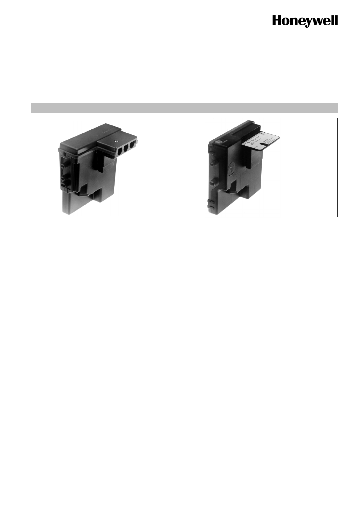
”Old”-- style
APPLICATION
The Combined Valve and Ignition system (CVI) has specially
been developed for application in gas fired appliances with
either intermittent pilot or direct burner ignition.
For this system, the VK41../VK81.. series gas controls have
been designed to have the S4565/S4575/S4585 series
ignition controls attached directly onto the valve.
The combined system then provides programmed safe light
up, flame supervision and regulation of gas flow to the main
burner and/or pilot burner of the appliance.
DESCRIPTION
The S4565/S4575 ignition controls provide automatic ignition
for direct gas burner applications and for intermittent pilot gas
burner applications with safety timer.
The S4565/S4575 ignition controls are not intended for direct
exposure to flame envelope.
The S4585 ignition controls provide automatic ignition for
intermittent pilot gas burner applications without safety timer.
The S4565/S4575/S4585 ignition controls are designed to
meet the european standards:
EN 298: Automatic gas burner control systems.
EN 60730--1: Automatic electrical controls for house hold
and similar use.
The S4565/S4575/S4585 ignition controls can be used in
appliances according European standard for household
electrical requirements EN 60335 series.
The S4565/S4575 ignition controls are approved on the North
American standard ANS Z21.20 Automatic Ignition Systems.
NOTE: S4565SD is not an ignition control but an ignition
circuit and rectifier only
”New”-- style
Contents
Page
Dimensional drawing 2................................
Features 3...........................................
S4565A,B,P,Q 3.......................................
S4565C,D,R,T 4.......................................
S4565AD,BD,CD,DD,PD,QD,RD,TD “1000” series 7......
S4565AD,BD,CD,DD,PD,QD,RD,SD,TD “2000” series 13..
S4565AF,BF,CF,DF,EF,PF,QF, RF, TF 18..................
S4575A,B,C,D,P,Q,R,T 23..............................
S4585D 26...........................................
General considerations 27.............................
Electrical connections 28..............................
Subject to change without notice. Printed in the Netherlands.
EN1R--9161 0006R10--NE
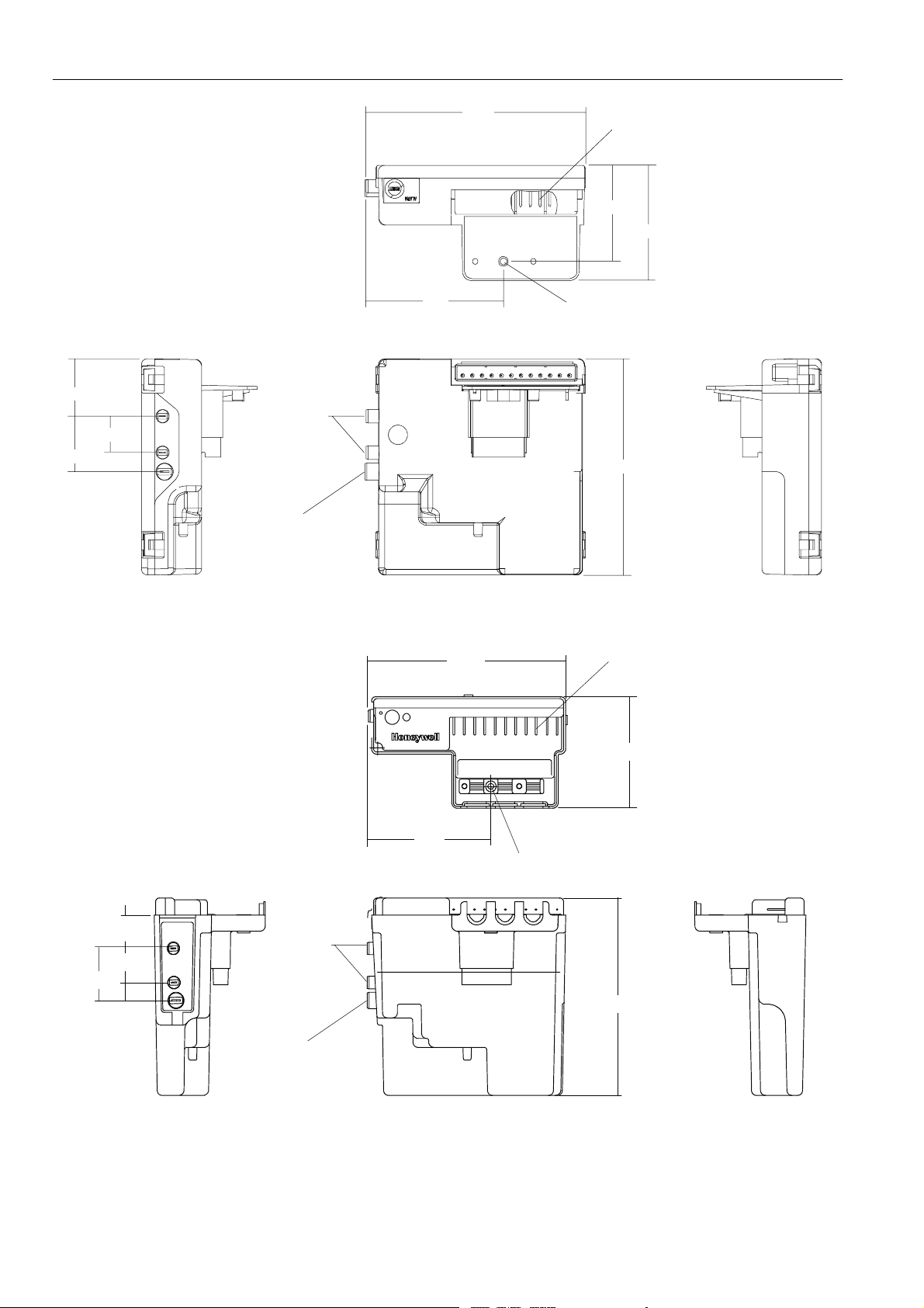
115
f
Connector pins suitable for
Molex 3001 female connectors
50
60
30
29
19
72
Mounting hole Ø 3.2
Ignition
113
Flame detection
Note: specific housings may deviate from drawing
Fig. 1. Dimensional drawing “new style” housing in mm
111
Connector pins suitable
Molex 3001 female connectors
or
18.5
19
29
EN1R--9161 0006R10--NE
69
69
Mounting hole Ø 3.2
Ignition
110
Flame detection
Note: specific housings may deviate from drawing
Fig. 2. Dimensional drawing “old style” housing in mm
2
62
FEATURES IGNITION CONTROLS
Flame supervision.
Built--in 2.5 ... 60 Hz ignition.
Internal or external reset and alarm.
Accurate safety timer.
Supply voltages of 220 ... 240 V in a single product.
Full operating sequence after flame loss.
Extended spark time.
Optional phase neutral independent operation, flame
sensing independent of safety ground potential for
S4565AD ... TD “2000” series and S4575.
Safety time triggered by Air Pressure Switch (APS) for
S4565AD ... TD “2000” series and S4575.
Optional safe separation flame relay output or opto
coupler.
Optional main burner interrupt for S4565 BF, DF, QF, TF.
Volatile or non volatile lock--out according EN 298.
EMC filter optional
Protective impedance flame rod
Under voltage protection
SPECIFICATIONS DIRECT BURNER IGNITION CONTROL S4565A, B, P, Q
Model
Suffix A: atmospheric, direct burner ignition
Suffix B: atmospheric, direct burner ignition, flame relay output
Suffix P: as A except volatile lock--out
Suffix Q: as B except volatile lock--out
Supply voltage
220 ... 240 Vac, 50/60 Hz
Power consumption
4VA
Humidity
90% RH max. at 40 _C
Ambient temperature
0 ... 60 _C
-- 15 ... 60 _C (optional)
Electrical rating (see also note 2.)
Alarm: 220 ... 240 Vac, 50/60 Hz, 1 A, cos ♥ > 0.6 or
1mAmax.
Flame relay contact: 220 ... 240 Vac, 50/60 Hz,
Flame opto coupler: +5 V, 10 kτ
Electrical connection
High voltage spark: 2.8 mm spade terminal
Flame sensing: 4.8 mm spade terminal
PCB connectors: Molex 3003 series suitable for Molex 3001
Housing (degree of protection)
See page 29
Timing (depending on O.S. number)
Self check time (T
1A,cos♥ > 0.6
female cable connector
): 1.5 s
c
Waiting time (T
Safety time (T
Extended spark ignition time: 0 ... T
Flame sensing
Min flame current: 0.9 ←A
Response time on: > 0.2 s
Response time off (T
Ignition
Spark voltage: > 12 kV at 40 pF load
Repetition rate: 2.5 ... 60 Hz (depending on O.S. number)
Max. spark gap: 3.5 mm
Length flame sensing cable
1mmax.
Length ignition cable
0.5 m max.
Length of wiring for external components
1mmax.
Remark
Optional integrated flame relay available with safe separation
or opto coupler with safe separation.
N.C. contact of flame relay has no safe separation.
): 0 ... 30 s
w
): 3.5 ... 55 s
s
FR
s
): < 1 s
(optionally other values available)
WARNING
Opto coupler interface needs a debounce time > 20
ms in order to prevent noise caused by transients on
mains.
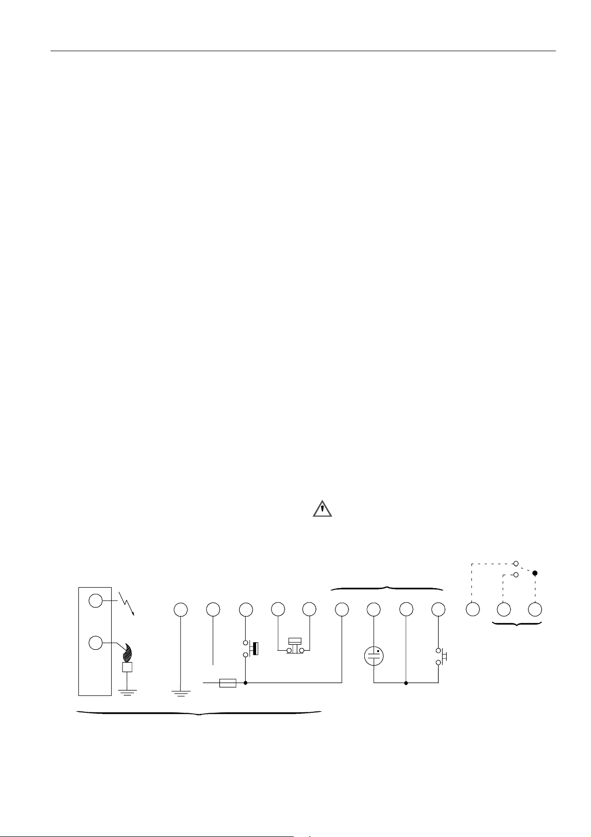
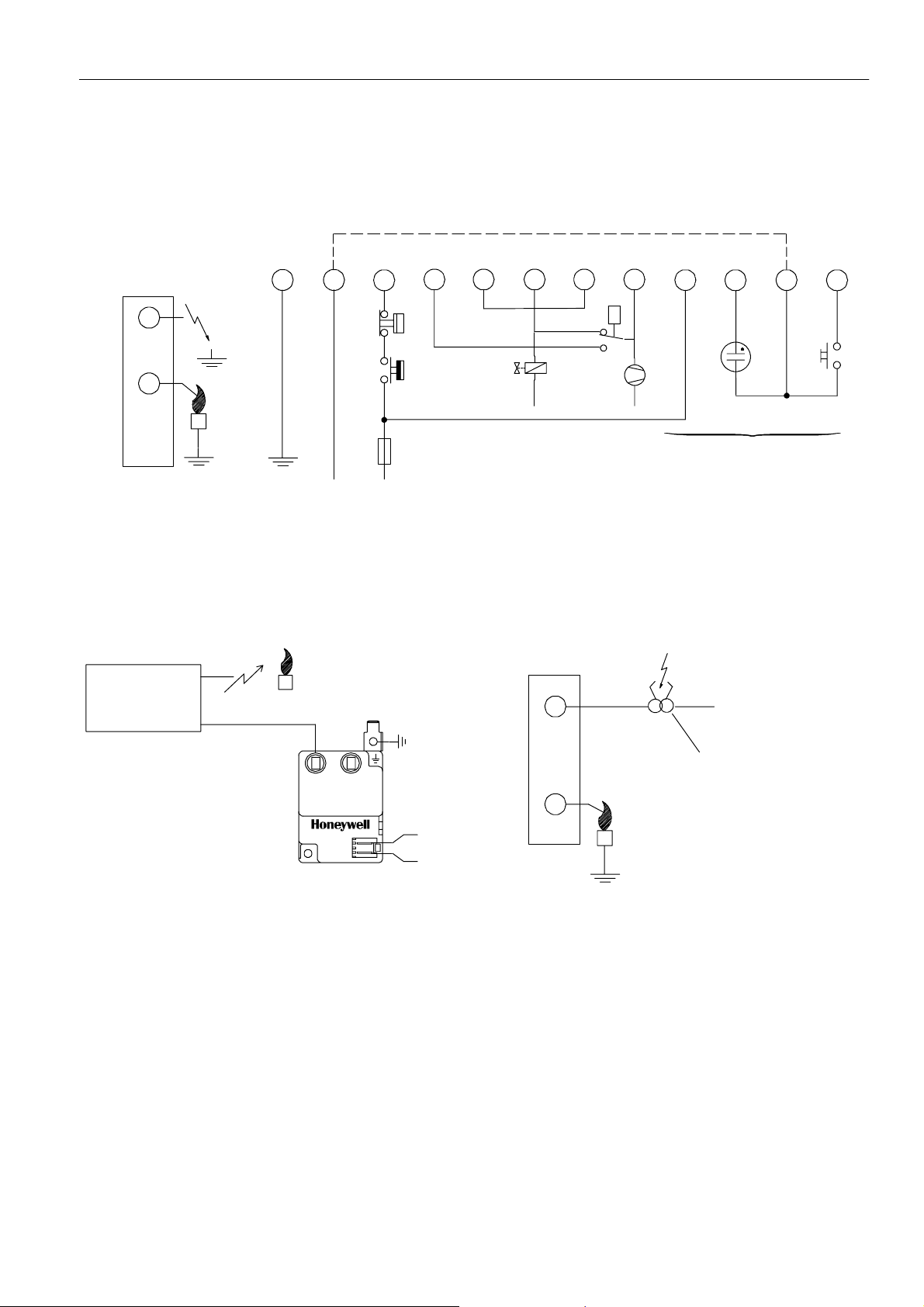
Side connections
12
N
L
All versions
Fig. 3. Connection diagram S4565A, B, P, Q
10
Optional
411
LM
8
3
7
65
*
9
3
Optional
RS
LM -- Limiter
RS -- Reset switch
* See note 2.
** See page 10 fig. 17.
EN1R--9161 0006R10--NE
Optional **
12
SYSTEM OPERATION
General
Lock- out reset
The S4565 ignition control can be reset by either depressing
the internal/external reset button (suffix A and B) or by
interrupting the permanent life (suffix P and Q).
NOTE 1.: If during normal use the reset button is pressed,
the gas valves drop out and the S4565 ignition
control starts a new sequence after releasing the
reset button.
NOTE 2.: If permanent alarm output:
neon indicator with integral resistor >150 kτ
Εmax 1 mA)
NOTE 3.: If an return high limit thermostat is used, the high
limit switch in the application needs a longer return
time than the trial for ignition time of the control.
This in order to provide non volatile lock out.
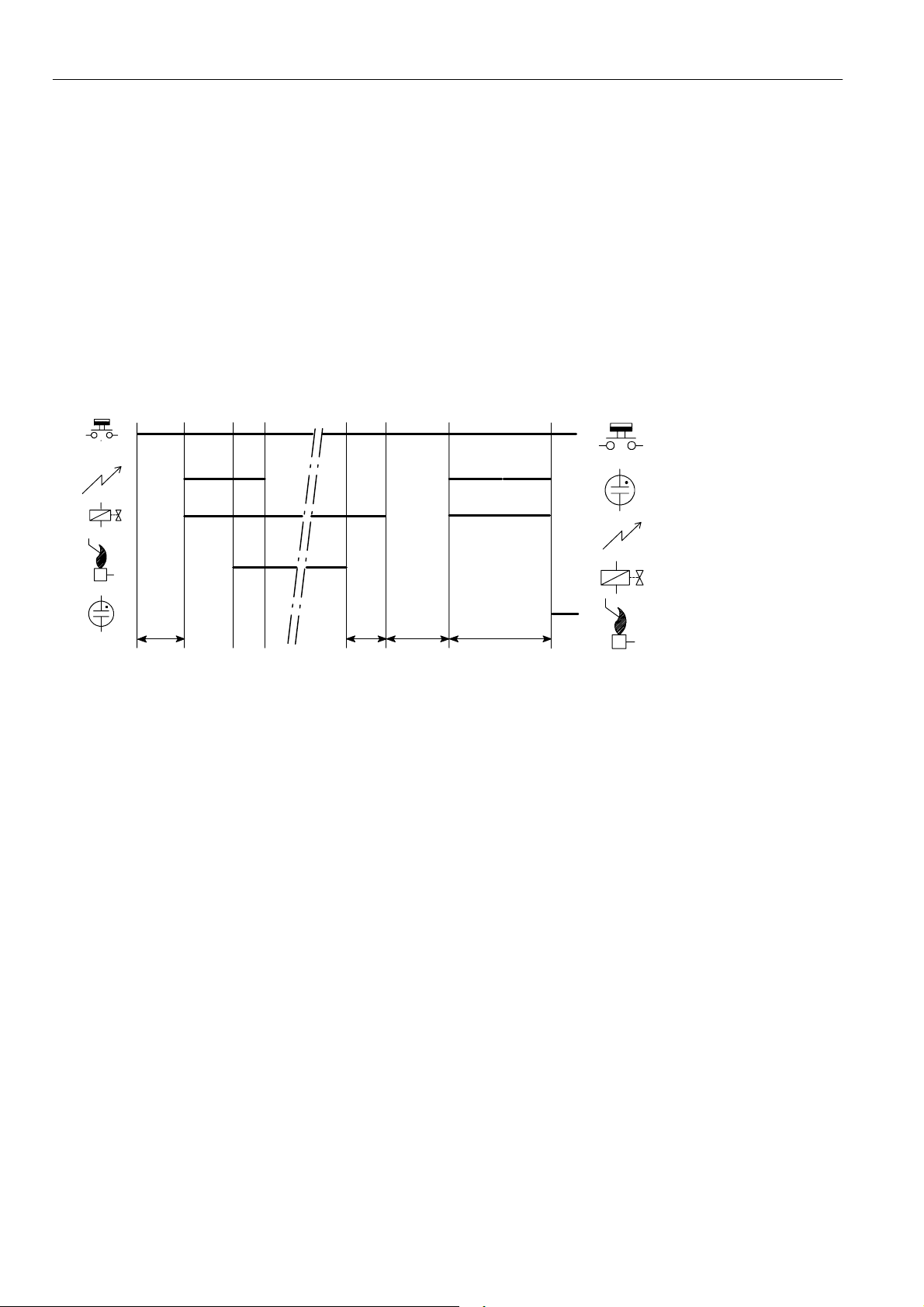
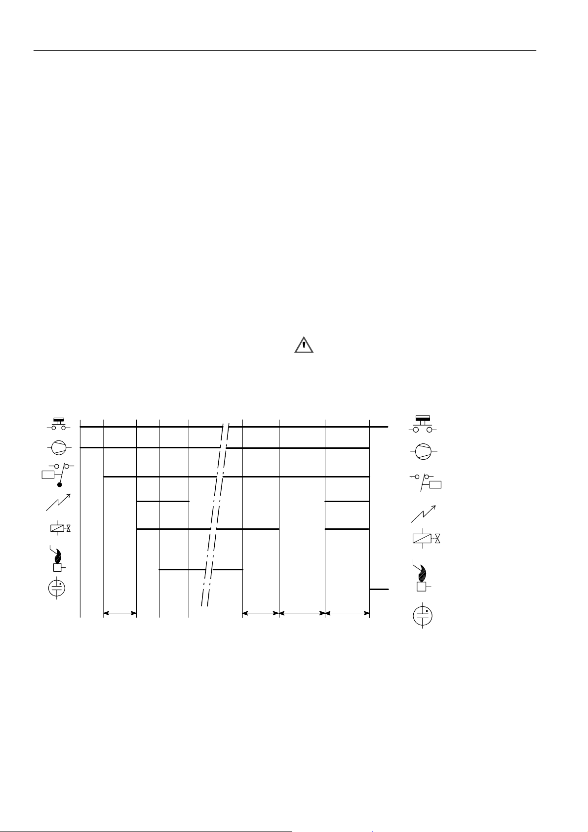
Suffix A, B, P and Q (see fig. 4.)
When there is a call for heat a self check period (T
waiting period (T
) elapse before built--in igniter and gas valve
w
)plus
c
are switched on.
The ignition spark ignites gas and resulting flame is detected
by the flame rod.
Ignition is switched off after extended ignition time and flame
establishment.
If flame is not established within the safety time (T
), the
s
S4565 ignition control locks out.
If the flame is lost during normal run, the S4565 ignition
control repeats start sequence.
Legend
Thermostat
Alarm
Ignition
Tc+T
Tc+T
w
T
FR
w
T
s
Fig. 4. Functional diagram S4565A, B, P, Q
SPECIFICATIONS IGNITION CONTROL S4565C, D, R, T
Model
Suffix C: fan assisted, direct burner ignition
Suffix D: fan assisted, intermittent pilot burner ignition
including safety timer
Suffix R: as C except volatile lock--out
Suffix T: as D except volatile lock--out
Supply voltage
220 ... 240 Vac, 50/60 Hz
Power consumption
4VA
Humidity
90% RH max. at 40 _C
Ambient temperature
0 ... 60 _C
-- 15 ... 60 _C (optional)
Electrical rating (see also note 5.)
Alarm: 220 ... 240 Vac, 50/60 Hz, 1 A, cos ♥ > 0.6 or
max 1 mA
Fan: 220 ... 240 Vac, 50/60 Hz, 1 A, cos ♥ > 0.6
LPG outdoor valve: 220 ... 240 Vac, 50/60 Hz, 1 A,
cos ♥ > 0.6
External ignition transformer: 220 ... 240 Vac, 50/60 Hz,
1A,cos♥ > 0.6
Electrical connection
High voltage spark: 2.8 mm spade terminal
Optional:
External mains voltage ignition transformer with
2.8 mm spade terminal
Flame sensing: 4.8 mm spade terminal or 2.8 mm spade
terminal for combined high voltage
spark/flame sensing
PCB connectors:Molex 3003 series suitable for Molex 3001
female cable connector
Housing (degree of protection)
See page 29
Timing (depending on O.S. number)
Self check time (T
Prepurge time (T
Safety time (T
c
p
): 3.5 ... 55 s
s
Extended spark ignition time and stabilisation time: 0 ... T
Flame sensing
Min flame current: 0.9 ←A
Response time on: > 0.2 s
Response time off (T
): 0, 1.5 or 2 s
): 0 ... 30 s
(dependent on elaps of safety time)
): < 1 s
FR
(optionally other values available)
Gas valve
Flame rod
s
EN1R--9161 0006R10--NE
4
Ignition
Spark voltage: > 12 kV at 40 pF load
Repetition rate: 2.5 ... 60 Hz (depending on O.S. number)
Max spark gap: 3.5 mm
Length flame sensing cable
1mmax.
Length ignition cable
0.5 m max.
Length of wiring for external components
1mmax.
Side connections**
ignition control
12
Special applications
input
11
10
8
LM
7
¯
LPG
N
P -- Air proving switch
LM -- Limiter
N
L
RS -- Reset switch
* See note 5.
** Alternative side connection for models with combined flame
detection/high voltage. See page 5 fig. 6.
Fig. 5. Connection diagram S4565C, D, R, T
Side connection
230 Vac
21
569
P
3
¯
24
*¯
1
RS
N
Optional
N
Ignition transformer
AT7030
N
L
Fig. 6. Alternative side connection for models with
combined flamedetection/high voltage.
Ph1
Ph2
Fig. 7. Alternative side connection for models with flame
sense input + 230 Vac output for external ignition
transformer
5
EN1R--9161 0006R10--NE
SYSTEM OPERATION
General
Lock- out reset
The S4565 can be reset by either depressing the
internal/external reset button (suffix C and D) or by
interrupting the permanent life (suffix R and T).
NOTE 4.: If during normal use the reset button is pressed,
he gas valves close and the S4565 ignition control
starts a new sequence after releasing the reset
button.
NOTE 5.: If permanent alarm output:
neon indicator with integral resistor >150 kτ
Suffix C and R (see fig. 8.)
When there is a call for heat the fan starts running through the
no air position of the air proving switch.
If an external LPG valve is connected, this will be energized.
When sufficient air flow is proven by the air proving switch, a
self check period (T
) and prepurge period (Tp)elapse before
c
the gas valve and built--in ignition or external ignition
transformer (optional) are switched on.
The ignition spark ignites gas and resulting flame is detected
by the flame rod.
Internal or external ignition is switched off.
After flame establishment a predetermined, extended ignition
time can be included.
If flame is not established within the safety time (T
S4565 ignition control locks out.
Εmax 1 mA)
), the
s
If the flame is lost during normal run, the S4565 ignition
control repeats the start sequence with prepurge.
If no air is proven by the air proving switch within the prepurge
time (T
running.
), the ignition control stays in waiting mode with fan
p
Suffix D and T (see fig. 9.)
When there is a call for heat the fan starts running through the
no air position of the air proving switch.
If an external LPG valve is connected, this will be energized.
When sufficient air flow is proven by the air proving switch, a
self check period (T
the pilot gas valve and built-- in ignition or external ignition
) and prepurge period (Tp)elapses before
c
transformer (optional) are switched on.
The ignition spark ignites pilot gas and resulting flame is
detected by the flame rod.
Internal or external ignition is switched off.
After flame establishment a predetermined, extended ignition
time can be included and flame establishment and the main
valve is switched on.
If flame is not established within the safety time (T
), the
s
S4565 ignition control locks out.
If the flame is lost during normal run, the S4565 ignition
control repeats start sequence at prepurge.
If no air is proven by the air proving switch within the prepurge
time (T
running.
), the ignition control stays in waiting mode with fan
p
WARNING
Do not interchange air proving switch wiring in order to
prevent malfunctioning
Legend
Thermostat
Fan
P
P
¯
Air proving switch
Ignition
Main valve
Flame rod
Tc+T
p
T
FR
Tc+T
p
T
s
Alarm
Fig. 8. Functional diagram S4565C, R
EN1R--9161 0006R10--NE
6
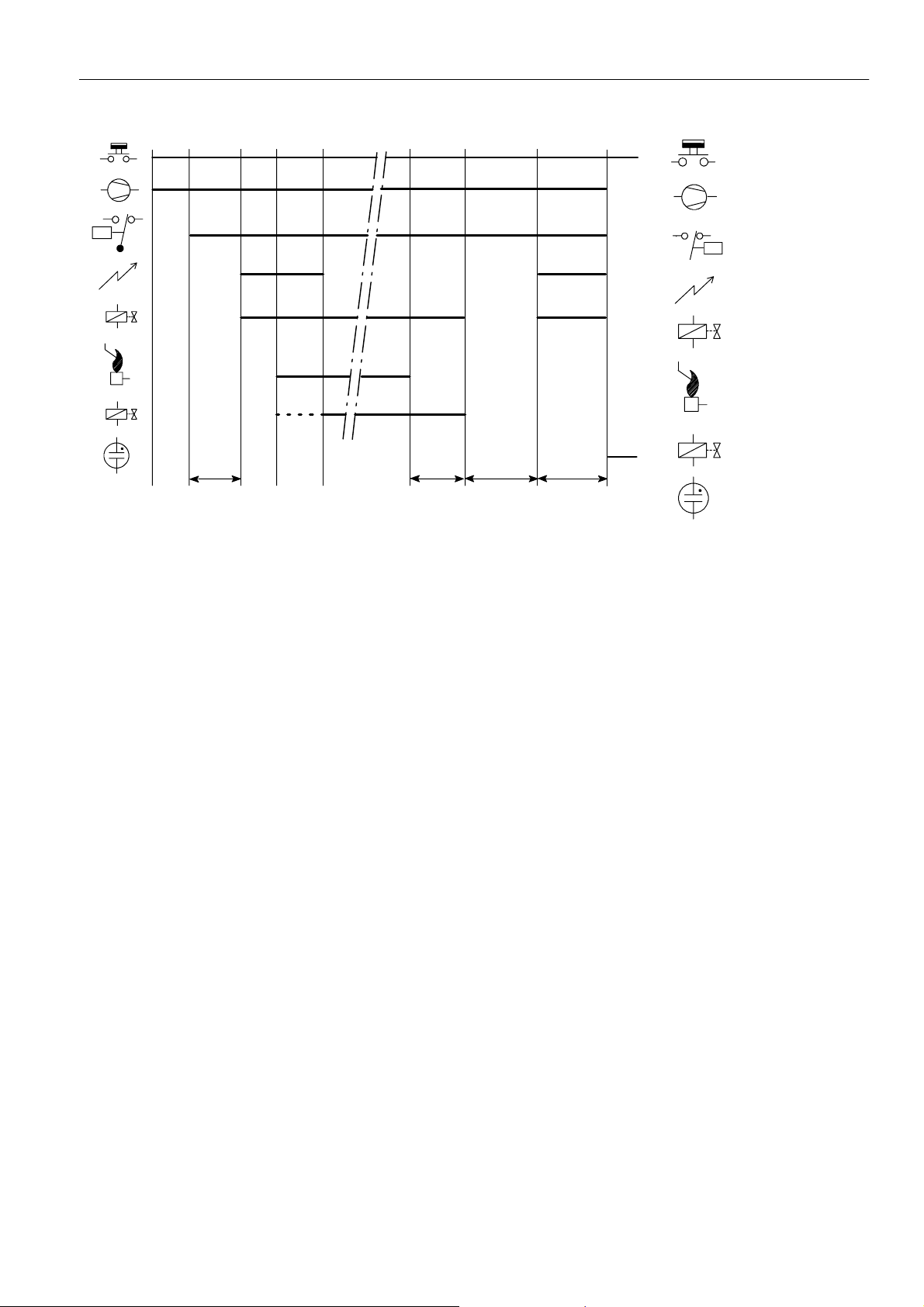
h
Legend
Thermostat
Fan
P
PV
MV
Tc+T
p
T
FR
T
c+Tp
T
s
Fig. 9. Functional diagram S4565D, T
SPECIFICATIONS DIRECT BURNER IGNITION CONTROL
S4565AD, BD, CD, DD, PD, QD, RD, TD “1000- SERIES”
Model
Suffix AD: atmospheric, direct burner ignition
Suffix BD: as AD but with flame relay output
Suffix CD: fan assisted, direct burner ignition
Suffix DD: as CD but with flame relay output
Suffix PD: as AD except volatile lock--out
Suffix QD: as BD except volatile lock--out
Suffix RD: as CD except volatile lock--out
Suffix TD: as DD except volatile lock--out
Supply voltage
220 ... 240 Vac, 50/60 Hz
Power consumption
4VA
Humidity
90% RH max. at 40 _C non condensing
Ambient temperature
0 ... 60 _C
-- 15 ... 60 _C (optional)
Electrical rating (see also note 8.)
Alarm: 220 ... 240 Vac, 50/60 Hz, 1 A, cos ♥ > 0.6 or max 1mA
Fan: 220 ... 240 Vac, 50/60 Hz, 1 A, cos ♥ >0.6
Flame relay contact: 220 ... 240 Vac, 50/60 Hz, 1 A,
cos ♥ >0.6
Flame opto coupler: +5 V, 10 kτ
LPG valve: 220 ... 240 Vac, 50/60 Hz,1 A max, cos ♥ >0.6
Electrical connection
High voltage spark: 2.8 x 0.5 mm spade terminal
Flame sensing: 4.8 x 0.8 mm spade terminal
PCB connectors: Molex 3003 series suitable for Molex 3001
Housing (degree of protection)
See page 29
Timing (depending on O.S. number)
Self check time (T
Waiting time (T
Safety time (T
): 1.5 s
c
): 0 ... 30 s
w
): 3.5 ... 25 s
s
Extended spark ignition time: 0 ... T
Flame sensing
Min flame current: 0.9 ←A
Response time on: > 0.2 s
Response time off (T
FR
Ignition
Spark voltage: >12 kV at 40 pF load
Repetition rate: 2.5 ... 60 Hz (depending on O.S. number)
Max. spark gap: 3.5 mm
Optional external ignition circuit: 220 ... 240 V (at no load),
Length flame sensing cable
1mmax.
Length ignition cable
0.5 m max.
Length of wiring for external components
1mmax.
P
¯
Air proving switc
Ignition
Pilot valve
PV
Flame rod
Main valve
MV
Alarm
female cable connector
(dependent on elaps of safety time)
s
): < 1 s
(depending on O.S. number)
single phase rectified, max 2 VA
7
EN1R--9161 0006R10--NE
Remark
Optional integrated flame relay available with safe separation
or opto coupler with safe separation.
N.C. contact of flame relay has no safe separation.
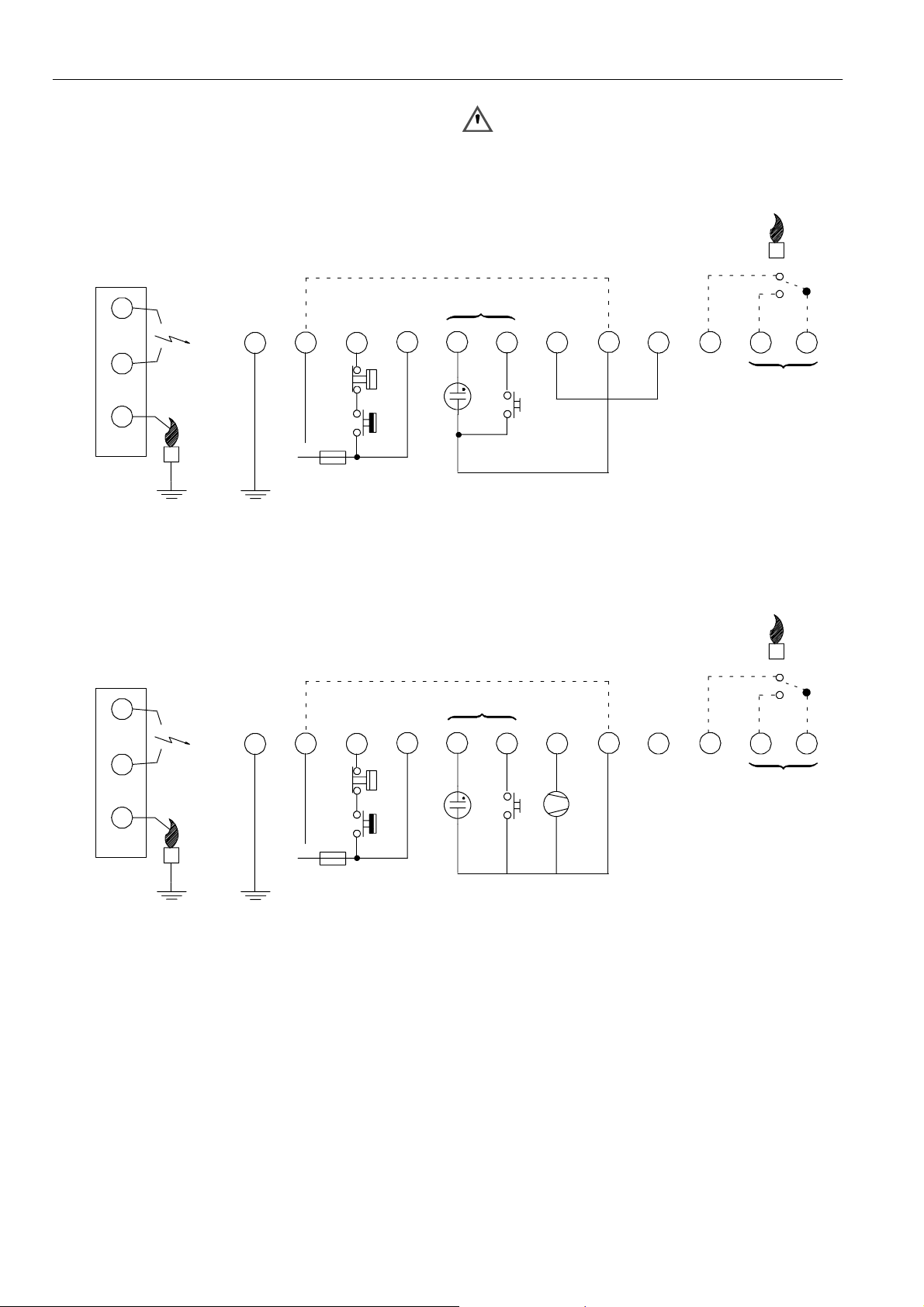
Side connections **
WARNING
Opto coupler interface needs a debounce time > 20
ms in order to prevent noise caused by transients on
mains.
Optional
Side connections **
10
9
LM
8
712
*
65
RS
N
L
Fig. 10. Connection diagram S4565AD and BD
Optional
10
9
LM
8
712
*
65
411
3
Optional ***
LM -- Limiter
RS -- Reset switch
* See note 8.
** See page 10 fig. 16.
*** See page 10 fig. 17.
411
3
Optional
Optional ***
12
12
Fig. 11. Connection diagram S4565BD and QD “1000” series for gas/air application
EN1R--9161 0006R10--NE
N
L
RS
* See note 8.
** See page 10 fig. 16.
*** See page 10 fig. 17.
8

Side connections **
Side connections
10
9
LM
8
712
*
65
RS
C
N
L
N
Fig. 12. Connection diagram S4565CD and DD
10
9
LM
8
712
*
65
+--
411
P
NC
3
Optional
Optional ***
12
¯
NO
P -- Air proving switch
LM -- Limiter
RS -- Reset switch
* See note 8.
** See page 10. fig. 16.
*** See page 10 fig. 17.
411
3
Optional ***Optional
12
Side connections **
N
L
N
Fig. 13. Connection diagram S4565QD with external ignition circuit
10
98 65
LM
712
*
N
L
Fig. 14. Connection diagram S4565PD and QD
LM -- Limiter
RS -- Reset switch
* See note 8.
*** See page 10 fig. 17.
411
3
Optional
Optional ***
LM -- Limiter
* See note 8.
** See page 10. fig. 16.
*** See page 10 fig. 17.
12
9
EN1R--9161 0006R10--NE
 Loading...